# Sketches
# Dimensions
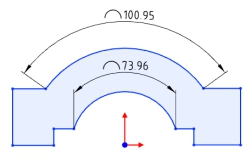
# Arc length annotations
Supports the creation of arc length annotations in sketches, and can be used as drive or driven dimensions.
Creation steps:
1) Click the [Label Arc Length] command in the Size Constraints drop-down menu.
2) Click the left button to select the arc edge line to display the arc size preview.
3) Click the left button again after moving the mouse to place the arc dimensions.
4) Continue to select other arcs that you want to label for continuous labeling.
5) Click the "Close" button to end the annotation.
Note:Only circular arc lines can be annotated.
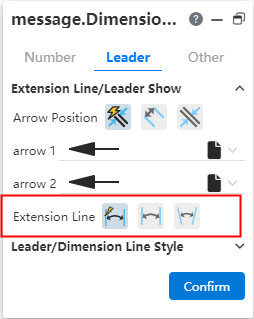
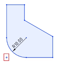
Label style:The size boundary style can be modified as shown in the following figure.
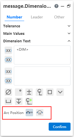
Arc symbol position:The arc length marked arc symbol position can be modified as shown in the following picture.
Note:When the radius and arc length are set at the same time, if the arc length value set is too large, resulting in the arc Angle x exceeding 360°, the actual arc Angle T= X-n *360, n is the maximum integer value when T is positive.
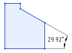
# Dimension boundary line optimization
The boundary line style of the dimensions is optimized to avoid dimensioning Angle dimensions that are out of the current window range.
Default style:The size boundary parameters can be set in System Settings - Document Properties - Dimensions.
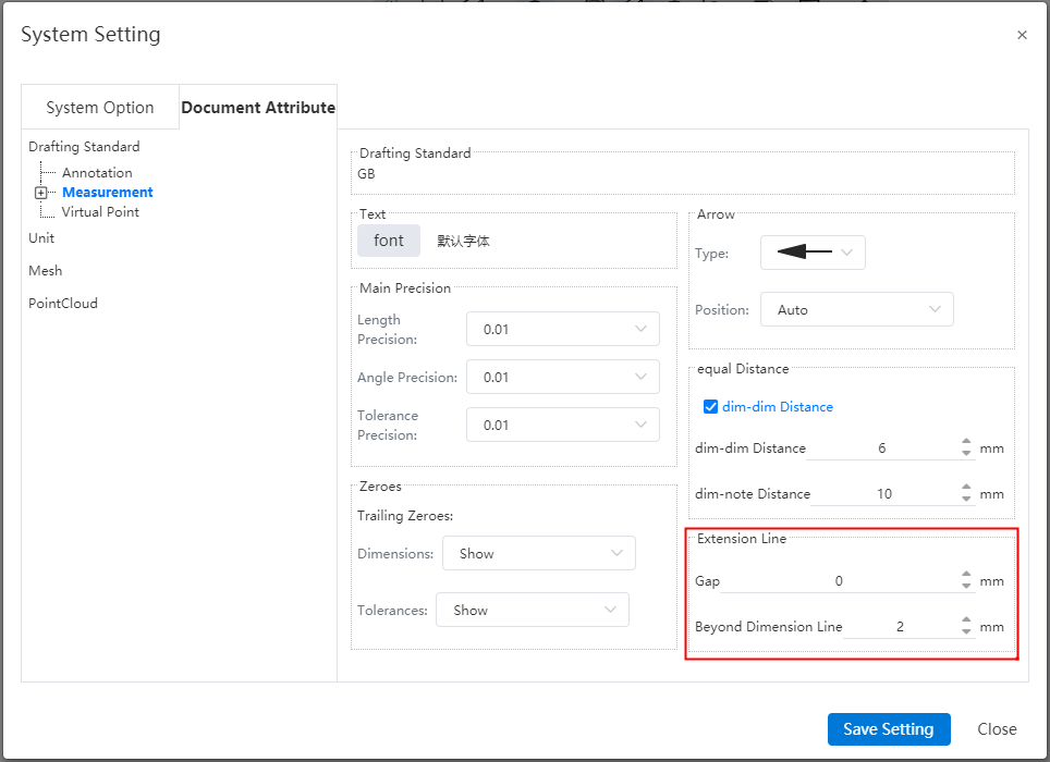
Gap:The gap between the size boundary line and the annotated element.
Beyond the size line length:The length of the size boundary line beyond the size line.
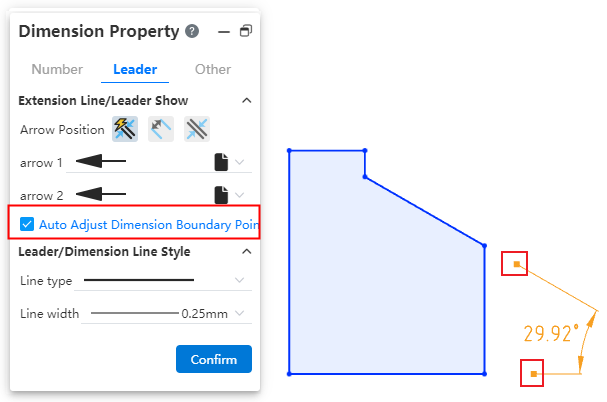
Manual adjustment:Select the Angle or length size, uncheck "Automatically adjust the size boundary end point" in the lead Tab of the size property dialog box, the square control mark is displayed at the end of the size boundary line, you can manually drag the control mark to adjust the boundary line. Check it again to restore the automatic adjustment of the boundary line.
# Virtual intersections
You can create virtual intersections where the extension lines of disjoint elements intersect for easy positioning during subsequent processing.
How to create:
- Method 1:Pre-pick element creation
1)Select two lines by holding down ctrl or by box picking, etc.
2)Click the "Draw Points" command or the "Virtual Intersection" command to generate virtual intersections.
- Method 2:Create using the Virtual intersection command
1)Click the Virtual Intersection command in the Draw Points drop-down box.
2)Select two lines.
3)Click the OK or Apply button to generate virtual intersections.
- Method 3:Create when dimensioning
1)Use the commands for dimensioning with size constraints.
2)Normal dimensioning.
3)Right click on element A where virtual intersections can be created.
4)Click Find Intersections.
5)Click another element B to generate A virtual intersection of A and B.
6)Continue annotating.
Elements that create virtual intersections:
Sketch lines, model edges, support to select the same/different types of lines to create virtual intersections
Straight lines, curves can be created on the extension line virtual intersection points.
When the selected line has multiple intersections, create the virtual intersections closest to the mouse click.
In the sketch, it is supported to pick up elements outside the sketch to create virtual intersections.
The use of virtual intersection points:
Analog sketch drawing points.
Supports adding dimensions, geometric constraints.
Measurements can be made.
Can be picked up in the feature dialog box, such as stretch boss feature picking points as directions, etc.
Special case:
Cannot be picked up as an outline in the lofting boss feature.
Sketch array and scale primitives The elements to be array/scaled do not support virtual intersections, scaled primitives' scale points support virtual intersections.
Virtual intersections Style:The display style of virtual intersections can be modified in "System Settings - Document Properties - Virtual intersections".
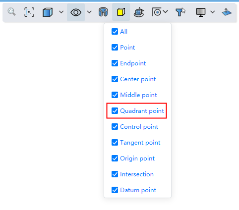
# Quadrant Points
Supports capturing quadrant points of circle/arc lines.
Start the drawing class command, the viewport displays the quadrant of the circle/arc line, which can be captured for drawing.
You can control whether to capture quadrantal points through the "Capture" function of the toolbar of the leading view.
# Mirroring
The mirror supports the selection of coordinate axes, which makes it easy to quickly create images that mirror relative coordinate values.
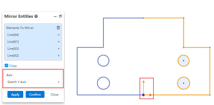
When using the mirror command, directly pick up the XY axis from the origin of the sketch in the viewport as the mirror axis to view the preview and create the graph.
# Add constraints to the center of the circle
The Add constraint command supports picking up the center of a solid surface circle edge without having to convert the boundary to generate a circle before picking up the center.
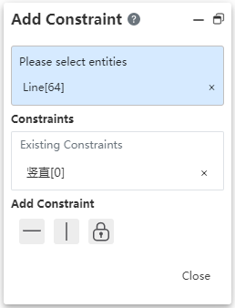
After opening the "Add constraint" command, the center of the circle is displayed after a short pause when the mouse points to the circular edge.
# 3D Sketch
# Equality constraint
Support to add equal constraints in 3D sketches, which is easy to draw sketches such as equal length solder paths.
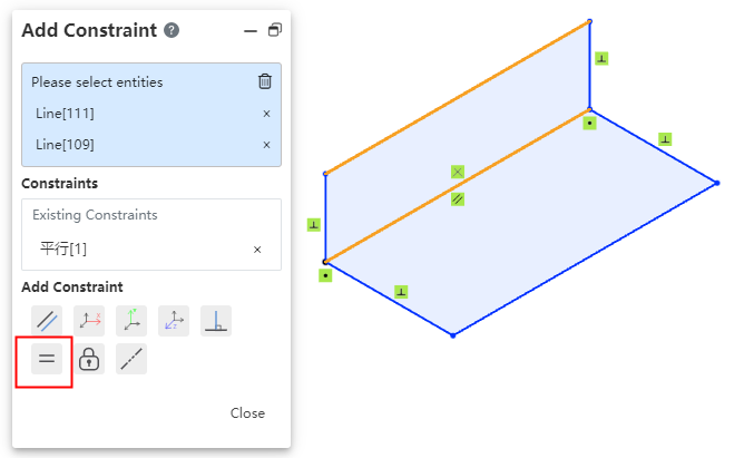
Choose two or more straight lines so that the lines remain equal in length.
Choose two or more circles/arcs so that the circle radii remain equal.
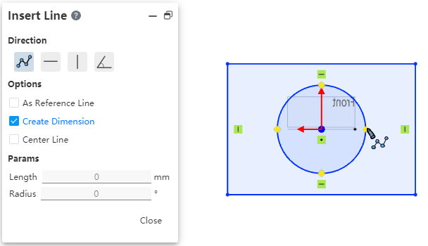
# Positioning sketch
Support for creating custom origin and XY orientation positioning sketches. You can choose the corresponding coordinate system or point as the center of the current sketch, which can reduce the drawing of many auxiliary lines and improve the design efficiency.
Creation method:
1)Click the Draw Sketch button.
2)Select the sketch plane and set the sketch origin and orientation as desired.
3)Click OK to generate the sketch.
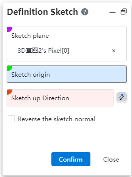
Dialog box control description:
Sketch plane: Required, single option. The plane surface of the datum, sketch/entity can be picked up.
Sketch origin: Optional, single option. Pickable points, points can be from sketch, solid, surface, curve, reference element.
Direction up the sketch: Optional. Line or two points can be picked up. Click the reverse button to reverse.
Reverse sketch normal: This button is not checked by default. After it is checked, the sketch normal direction is reversed.
# Offset
# Bilateral symmetry
Support bilateral symmetry, improve design efficiency, can offset two lines at a time.
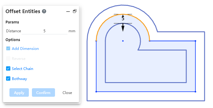
Usage:Check the "bidirectional" option in the offset dialog box to generate the offset line with bilateral symmetry.
# Offset circle adds constraint
Add constraints and offset distance dimensions after offset circle/arc.
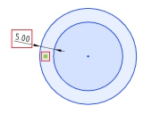
Removing the constraint cancels the offset effect between the two circles.
Modify Offset distance Dimension value To change the offset distance.
Use the Size Constraint command to add offset dimensions between concentric circles.
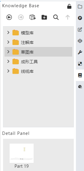
# Sketch Gallery
The 2D sketches in the parts can be saved to the knowledge base for quick follow-up calls and improved design efficiency.
# Add to library
Method 1:
1)Right-click sketch in feature list and click [Add to Knowledge Base].
2)Set the name and storage location in the Add to Knowledge Base dialog box.
3)Click OK to finish adding.
Method 2:
1)Open the knowledge base and click Add to Library.
2)Pick up the sketch in the feature list or viewport.
3)Set the name and storage location in the Add to Knowledge Base dialog box.
4)Click OK to finish adding.
Note 1:After the sketch is stored in the library, the internal constraints of the sketch remain, and the external constraints are automatically deleted. For example: the horizontal constraints of the line are retained, and the isometric constraints of the line and the external line are deleted.
Note 2:The sketch entered into the library is disconnected from the source sketch, and any modifications made by the source sketch do not affect the sketch in the library.
# Call sketch
Method 1:
1)In the Sketch Gallery Details panel, select Sketch and right click the [Insert] button.
2)Set the sketch location in the Locate Sketch dialog box and click OK to enter the sketch.
3)To display the preview in the sketch, select the location you want to place according to the preview by clicking the left mouse button.
4)Multiple identical elements can be generated by left-clicking in different locations.
5)Exit the sketch.
Method 2:
1)Select sketch from Knowledge Base in document, drag to viewport and release left mouse button.
2)Set the sketch location in the Locate Sketch dialog box and click OK to enter the sketch.
3)To display the preview in the sketch, select the location you want to place according to the preview by clicking the left mouse button.
4)Multiple identical elements can be generated by left-clicking in different locations.
5)Exit the sketch.
Method 3:
1)Create and go into a sketch.
2)Select the sketch from the Knowledge Base in the document, right click the Insert button, or drag into the viewport to release the left mouse button.
3)To display the preview in the sketch, select the place to place according to the preview and click the left mouse button.
4)Multiple identical elements can be generated by left-clicking in different locations.
5)Exit the sketch.
# Manage Sketches
Right-click the sketch you want to manage in the sketch gallery to "Delete, rename, edit".