# Assembly
# Cam
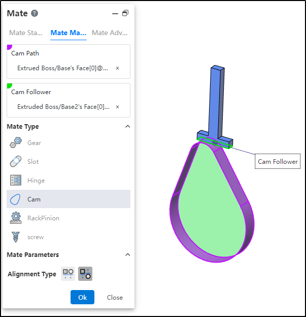
Added a new cam mate type to meet the requirements of various scenarios.This fit ensures that the cam maintains the correct motion and position of the follower during operation.
How to use:
After inserting the cam and follower parts, click the "Mate - Mechanical - Cam" command.
Select the cam groove, pick the element; successful selection will be highlighted in purple.
Select the cam follower, pick the element; successful selection will be highlighted in green.
In the "Alignment Type" section, choose the desired alignment method.
Click OK to generate the feature.
Note: The elements that can be picked for the cam groove and cam follower are points and faces. The profile sketch of the cam groove must form a closed loop, and there must be a tangent constraint between two connected lines. If features are added to the face used as the cam groove, breaking its continuity, the face cannot be picked as a cam groove element.
# RackPinion
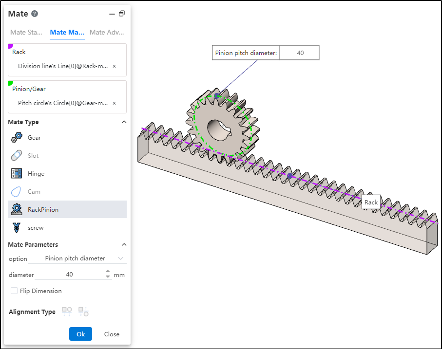
Added a new rack and pinion mate type to meet the requirements of various scenarios. This mate enables the gear part to rotate through the linear translation of the rack part.
How to use:
After inserting the gear and rack parts, click the "Mate - Mechanical - Rack and Pinion" command.
Select the rack and pick the element (commonly the rack pitch line); successful selection will be highlighted in purple.
Select the pinion gear and pick the element (commonly the gear pitch circle); successful selection will be highlighted in green.
In the options, check either "Pinion Pitch Diameter" or "Rack Stroke/Revolution," and the system will automatically calculate the value. Additionally, users can manually set the parameters.
Decide whether to check "Reverse Dimension" based on your needs.
Click OK to generate the feature.
Note: Both rack and pinion support curves, cylindrical surfaces, and arc surfaces as pickable elements. This mating type can also be applied without drawing a gear, and can be achieved using linear edges, circular edges, and other features.
Dialog Box Control Instructions:
Pinion Pitch Diameter: The pitch circle diameter of the gear.
Rack Stroke/Revolution: π × the pitch circle diameter of the meshing gear.
Reverse Dimension: By default, the gear rotates clockwise while the rack translates in the negative direction. When the "Reverse Dimension" option is checked, the gear still rotates clockwise, but the rack now translates in the positive direction.
# Path Mate
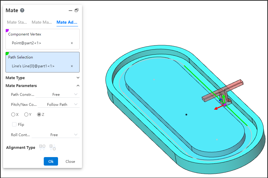
A new "Path Mate" type has been added to advanced mates, meeting requirements across various scenarios. The path mate constrains selected points on components to a path, and allows users to define deviations, swaying, and other behaviors as the component travels along the path.
How to use:
After inserting the parts, click the "Mate - Advanced - Path Mate" command.
Select the part vertex and pick the point element.
Select the path and pick the sketch profile, solid edge, or curve.
Choose the path constraint type based on your needs.
Choose the pitch/yaw control type based on your needs.
Choose the roll control type based on your needs.
Click OK to generate the feature.
Dialog Box Control Instructions:
Path Constraint: Choose how the component moves along the path.
Free: The component can move freely along the path.
Distance along Path: The component is fixed at a specific distance along the path and cannot move, but can rotate freely around the vertex.
Percentage along Path: The component is fixed at a specific percentage along the path and cannot move, but can rotate freely around the vertex.
Pitch/Yaw Control: Choose the pitch angle and orientation of the component as it moves along the path.
Free: The component can freely adjust its pitch while moving along the path.
Follow Path: By selecting a 3D coordinate direction, the component maintains a consistent pitch orientation during movement.
Roll Control: Choose the roll angle and direction of the component as it moves along the path.
Free: The component can rotate freely while moving along the path.
Up Vector: Ensures the rotational orientation of the component during movement by selecting a constraint element and a three-axis direction.
# Liner/Liner Coupler
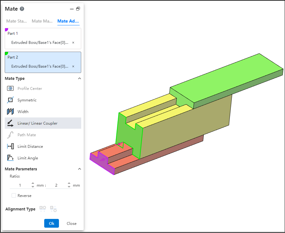
A new "Linear/Linear Coupling" mate type has been added to advanced mates, meeting requirements across various scenarios. By establishing a geometric relationship between the translation of one component and the translation of another, motion can be defined for each component relative to the ground or a reference component.
How to use:
After inserting the parts, click the "Mate - Advanced - Linear/Linear Coupling" command.
Select Part 1 and pick the element; this element serves as the reference during linear movement.
Select Part 2 and pick the element; this element establishes a proportional distance relationship with the reference element during linear movement.
Set the ratio.
Decide whether to check "Reverse" based on your needs.
Click OK to generate the feature.
Note: The ratio indicates that when the first component moves a certain distance, the second component moves a corresponding distance based on the predefined ratio relative to the reference. For example, a ratio of 1:2 means that when the first component moves 1 mm, the second component moves 2 mm relative to the reference element.