# Piping Layout
The pipe laying command creates a pipe in a pipe document, creates a pipe path by dragging the axis in the viewport or picking two points, and creates a pipe along the path based on the selected wall thickness grade and diameter.
# Drag
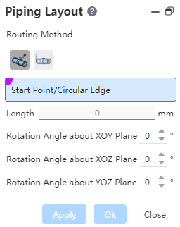
To use:
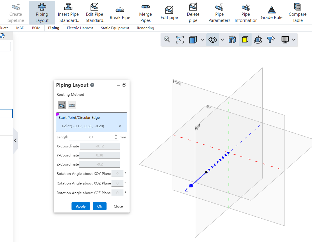
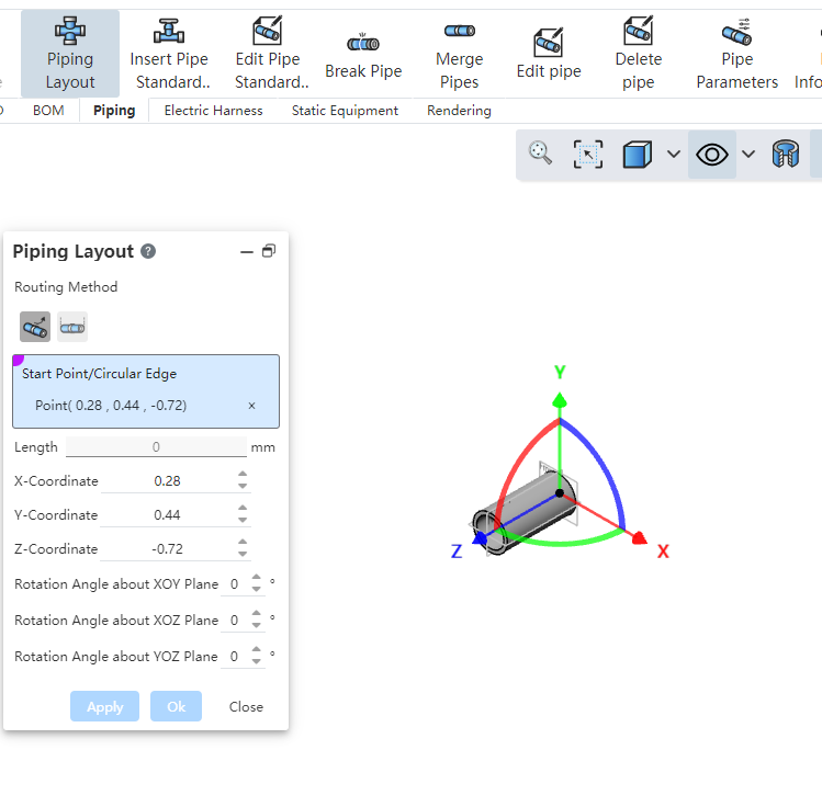
Select sketch points, solid points, tube midpoints, endpoints, circular edges, or any blank space in the viewport and click to determine the starting point.
After picking up the starting point, the point coordinates are displayed, and the viewport displays a drag-and-rotate coordinate axis with the point as the origin.
Mouse drag axis translation or rotation to create a pipe path, you can also enter the length size or rotation Angle, click apply or OK to create a pipe.
When selecting the midpoint pipe layout on the pipe, a three-way standard part is automatically added between the original pipe and the new pipe, and the original pipe is divided into two separate tubes.
# Two-Point
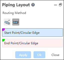
To use:
Select the starting point of the pipe, you can pick up sketch points, solid points, pipe endpoints, circular edges or any blank position.
Select the end point: consistent with the type supported by the starting point.
Click Apply or OK Build Tube.
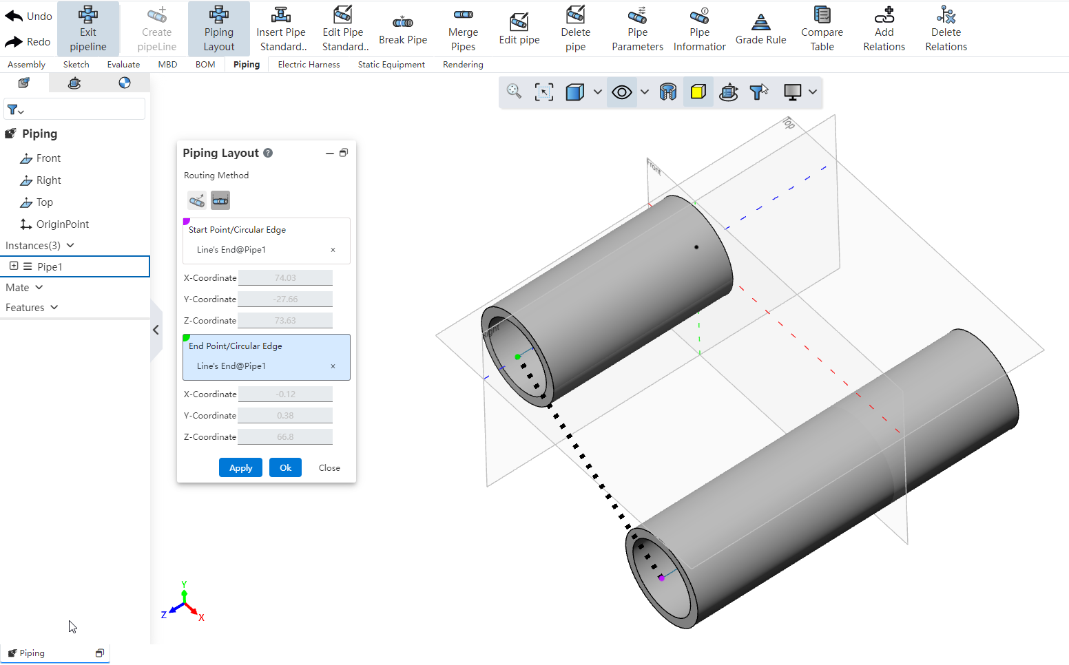
【Explanation】
When selecting a blank position to do the starting point, you can modify the position by entering the coordinate value.
When the pipe path end is selected to create a connected pipe, the connection is automatically handled according to the type of bend.