# Drawing Format
# Edit Drawing Format
Edit drawing frame and title bar text as follows:
- Click the command
 "Edit Drawing Format" to enter the "Edit drawing format" state.
- The Edit Drawing format command changes to exit edit drawing format.
- Hide the views, annotations, and sketching elements within the current drawing and display only the frame and title bar text.
- The lines in the frame and title bar can be selected and deleted or dragged to modify the position/length.
- Allows you to switch to the sketch module and draw your own frame or title bar.
- A sketch drawn in the "Edit Drawing Format" state belongs to the frame.
- Use the dimensions and constraints in the sketch module to constrain the frame lines.
- The dimensions and constraints created for the drawing frame are only visible in the Edit Drawing Format status
- Click on the "Exit Editing Drawing" format, and the frame and title bar become the modified style.
- The size and constraint information of the picture frame are hidden
- Restore display views, annotations, and sketching elements
- Edit drawing format only works for the current document.
# Automatic Border
Support for automatic generation of drawing boxes and area labels in drawing formats.
- Startup method: In the "Edit drawing format" state, you can choose to start the "automatic border".
- Settings:Provide two types of Settings: delete elements and boundary parameters.

Delete elements: Batch delete unnecessary lines or comments and other elements in the current drawing format;
Boundary parameters: Provide the function of custom boundary parameters, which can be set and selected on demand to achieve the setting of the area size and margin of the picture frame.

How to use:
Enter the Edit Drawing format state and click the "Automatic Boundary" command.
Switch to the "Boundary Parameters" Tab.
Set the parameters as desired.
Click OK to finish creating the boundary.
Parameter description:
Area Size: Set the rules for dividing the area and the total dividing area.
Margin: When the total division area is set to "Border", control the distance of the border to the right and left above and below the drawing.
Double-line border: A circle of border lines is generated on the outside of the bounding box to form a double-line border.
Independent border: The margin of the boundary line is the same as the margin of the zone division by default, and you can set a separate margin for the boundary line by checking the independent border.
Zone divider line: Set whether to display zone divider line and the length of zone divider line.
Zone labels: Sets the explicit and hidden status and position of row and column labels.
Font: Sets the font for the region label.
# Customize Drawing Size
Support for custom drawing sizes.
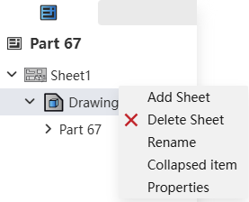
- Startup method:Open the drawing property setting box by right-clicking "Drawing" on the left side of the project drawing and selecting "Properties".
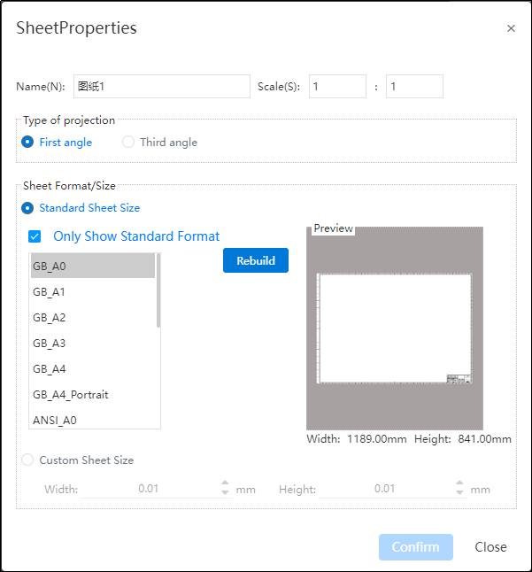
- Drawing properties:Standard drawing size and custom drawing size can be selected.
1)Standard drawing size: that is, drawings that meet GB, ANSI, ISO three standards;
2)Custom drawing size: you can specify the size of the drawing by entering the width and height. Allowable range with [0.00001, 10000000], in mm.
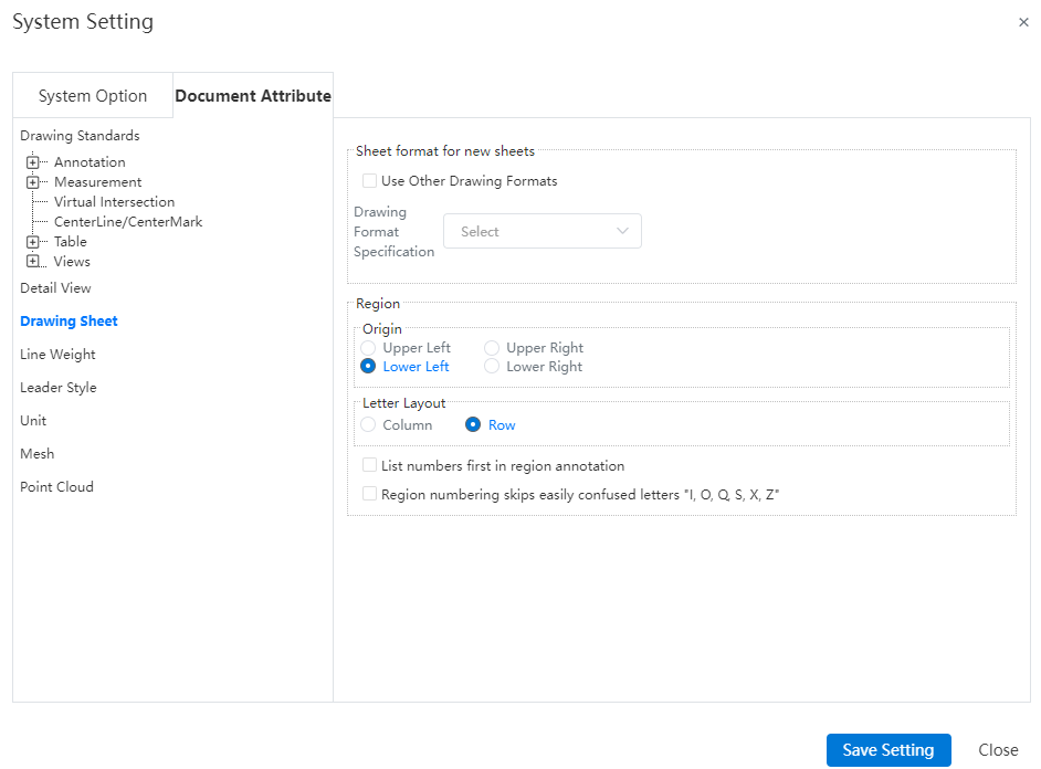
Origin:Set the area number from that corner, specify a corner in the "top left (default), bottom left, top right, bottom right" of the four corners. If "Top Left" is selected, the area in the top left corner is area A1, and the other areas are sorted to the right and down in order.
Letter layout:You can set letters to represent rows or columns. When letters represent rows, numbers represent columns; Vice versa when letters represent columns, numbers represent rows.
List the numbers first in the zone annotations:By default, the zone annotations are the letters first, such as A1, B3, etc. Check this to make the numbers come first, such as 1A, 3B, etc.
Can set whether to skip the confusing letters in the field number:I,O,Q,S,X,Z。
Instructions:
- When the drawing size is customized, the drawing format content is blank, and the drawing frame title bar is not automatically generated, etc., and the user can add it by editing the drawing format function.
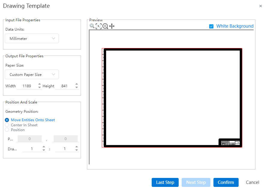
# Import DWG Template
You can save imported DWG, DXF drawings as engineering drawing drawing templates.
- Startup method:Open the imported DWG and click "Save as engineering drawing template" in the save.
2.Through the selection of layers, you can determine the DWG elements saved to the template.
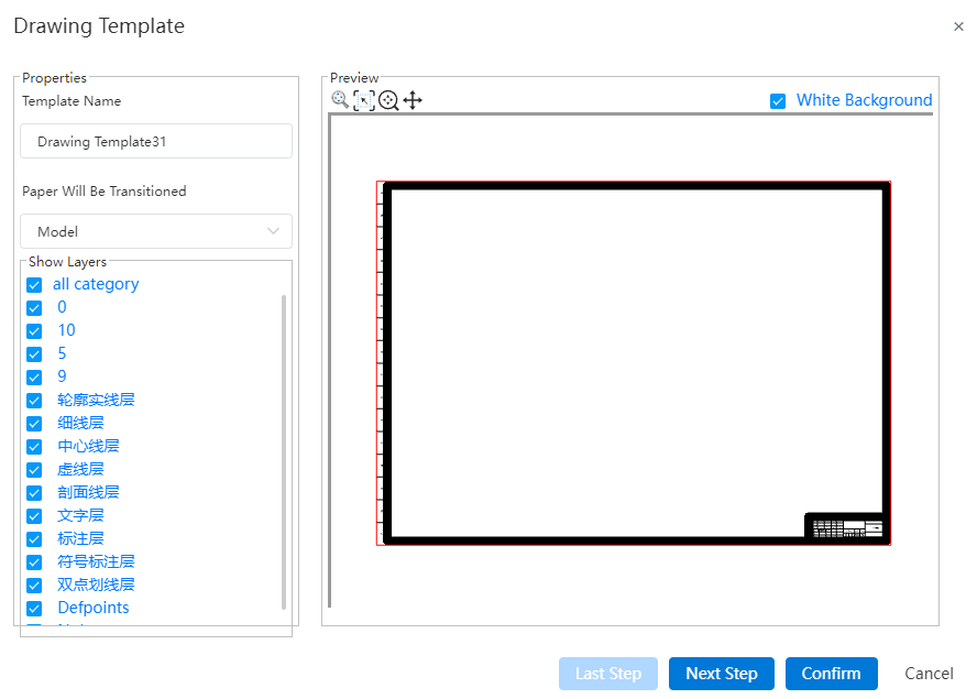
- You can set the drawing size of the template (template or custom), positioning and scaling ratio.
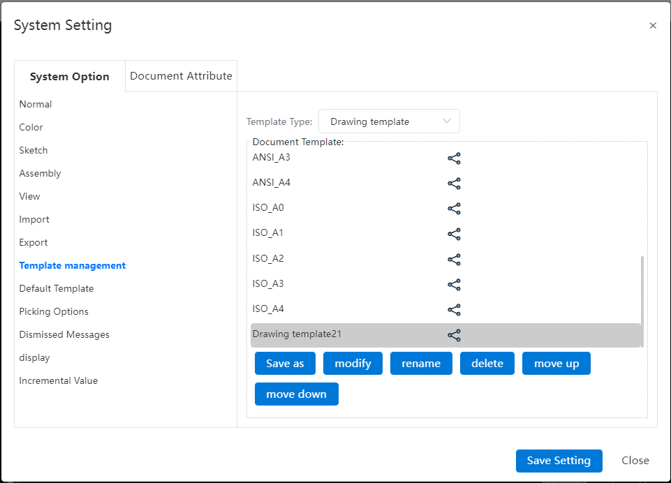
- After the template is saved, it can be managed by "System Settings - Template management - Engineering Drawing Template".