# Welding Symbol
Generate welding symbol annotation in the engineering drawing, creating steps are as follows:
- Click the welding symbol command
 to pop up the welding symbol dialog box.
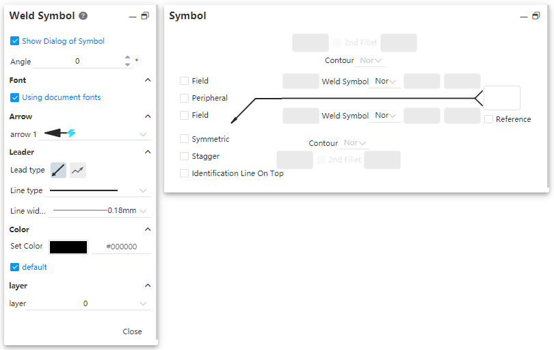
- Go to the basic Settings in the "Welding Symbol" dialog box on the left
- The display symbol window is checked by default, and after it is checked, the right "symbol" window is displayed for setting the symbol content.
- Symbol Angle, font, lead and color Settings and other annotation functions.
- Symbol dialog box control description:
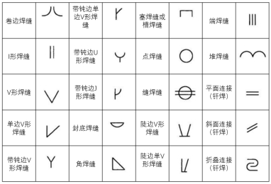
- Welding symbol: Click the pop-up drop-down box for selecting the welding symbol
Input box 1.2.3.4.5: Used to input the text displayed in the symbol, which needs to meet certain conditions in order to become input
- Conditions for becoming input state
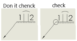
An input box Conditions 1.2 Solder symbol Select an option other than "None" 3.4 Check the "Second rounded corner" option 5 Check the "Interlaced interrupts" option Second rounded corner: Sets whether to display the second rounded corner symbol on the welding symbol


- Uncheck, the second rounded corner symbol will not be displayed, as shown on the left in the image above;
- Check it to display the second rounded corner symbol, as shown above on the right
- Available only when the welding symbol is selected "I-shaped weld, single side V-shaped weld, single side V-shaped weld with blunt edge, Jshaped weld with blunt edge", other welding symbols cannot be checked with the second rounded corner option.
Contour shape: Add the corresponding contour symbol above the weld symbol
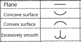
- Optional "None" and above type


- When selecting a type other than none, the outline symbol appears over the welding symbol, as shown on the left in the image above.
- If a second rounded corner symbol exists in the symbol, the outline symbol appears on the second rounded corner symbol, as shown in the image above.
Field: Controls whether to display the field symbol of the small flag style.
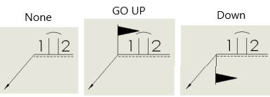
- If it is not checked, it will not be displayed, the effect is as "none" in the picture above.
- Check "live" at the top, above "on"
- Check "Scene" on the bottom, "bottom" on the top
Full Week: Controls whether the full week symbol is displayed
Symmetry: Controls whether the symbols above and below the horizontal line are displayed symmetrically


- Uncheck (default), normal display, as shown on the left in the image above
- After it is checked, "Welding symbol" and "outline shape" in the red area will be displayed symmetrically under the horizontal line, while the content of input box 12345 will not be displayed under the horizontal line, as shown on the right in the above picture; The setting item in the blue area becomes gray and cannot be set.
- The Symmetric and Interleaved options can select at most one item at the same time
Interleaved interrupts: Controls whether a broken line symbol representing interleaved interrupts is displayed after the 2. This option is not checked by default.

- After being checked, the effect is as shown in the picture above, with the following precautions
- The "welding symbol" on the horizontal line is displayed symmetrically under the horizontal line, the "outline shape" is not displayed, and the middle dotted line is not displayed
- The "Weldment symbol" and "Outline Shape" in the blue area can be set, but it does not take effect.
- The text of the input box 12345 in the blue area is valid and normally displayed in the corresponding position of the viewport.
- The "symmetric" and "Interleaved intermittent" options can be selected at most one at the same time.
Display mark line at the top: Control whether to reverse the position of the dotted and solid lines
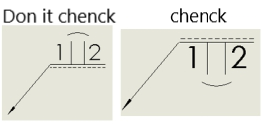
- Unselected by default, solid line and red box area content on the top, dotted line and blue box area content on the bottom
- After it is checked, swap the upper and lower positions of the dotted and solid lines and the content of the corresponding area.
- This option is not available when the "Symmetry" option is checked.
Tail annotation input box: Used to enter text such as remarks
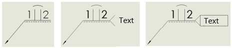
- The text box is empty by default, as shown on the left in the image above
- Split ends and text are displayed after typing, as in the image above
- After entering the text, you can check the "reference" option, after checking the text is surrounded by boxes, as shown on the right in the picture above
- Reference form and position tolerances such as welding symbol insertion, generation method, re-editing, and association relationship with engineering drawing view.