# Hole Callout
Support the selection of circular outline in the engineering drawing to generate hole annotation, the operation steps are as follows:
- Click the hole annotation command
 to pop up the hole annotation dialog box.
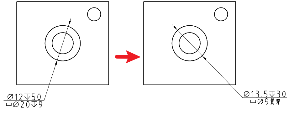
- When marking the holes generated by the hole command, the relevant parameters of countersunk head/taper hole/thread can be automatically marked. The marking effect is as follows:

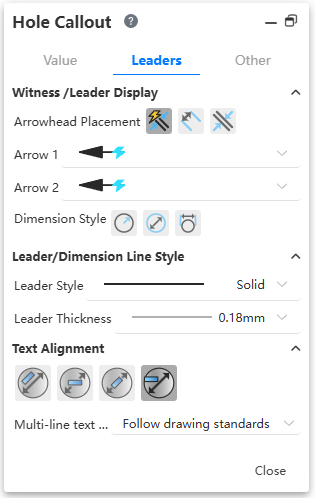
- Hole annotation supports diameter radius switching. Set this at the Hole labeling dialog box "Lead - Size Line/Lead Display - Diameter/Radius" :
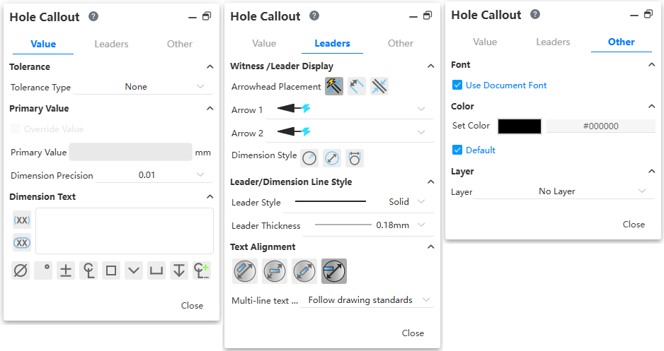
- The content of the hole marking dialog box "marking size text box" corresponds to the text information of the hole marking, and the content is composed of "special symbol, associated size, text" :
- Tolerance, covering size, prefix and suffix text and other functions:
- Tolerances appear after the diameter dimensions of the main property
- After checking the cover dimensions, all the data as a whole is covered and replaced.
- The front/back/overfix text is displayed on the horizontal line, respectively, before/after/above the original data.
- The front/back/overfix text is displayed on the horizontal line, respectively, before/after/above the original data.
The other Settings are the same as the smart size, and the commonly used symbol function is also available in the smart size.
The number of holes generated by the same hole feature can be recognized and automatically marked.
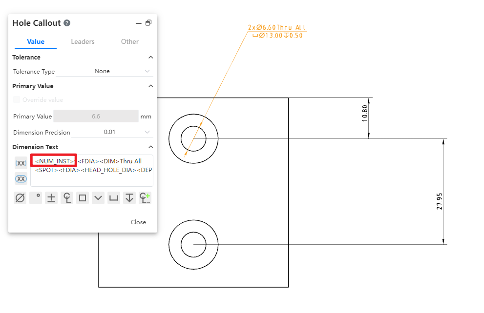
Note: Only the number of holes generated by the same hole feature will be automatically recognized. Delete <NUM_INST> in the text box and enter the number to modify the number to a custom one.
- Thread depth is not displayed for through-thread.

Note: Only the depth selection of the full penetration mode can be correctly identified.
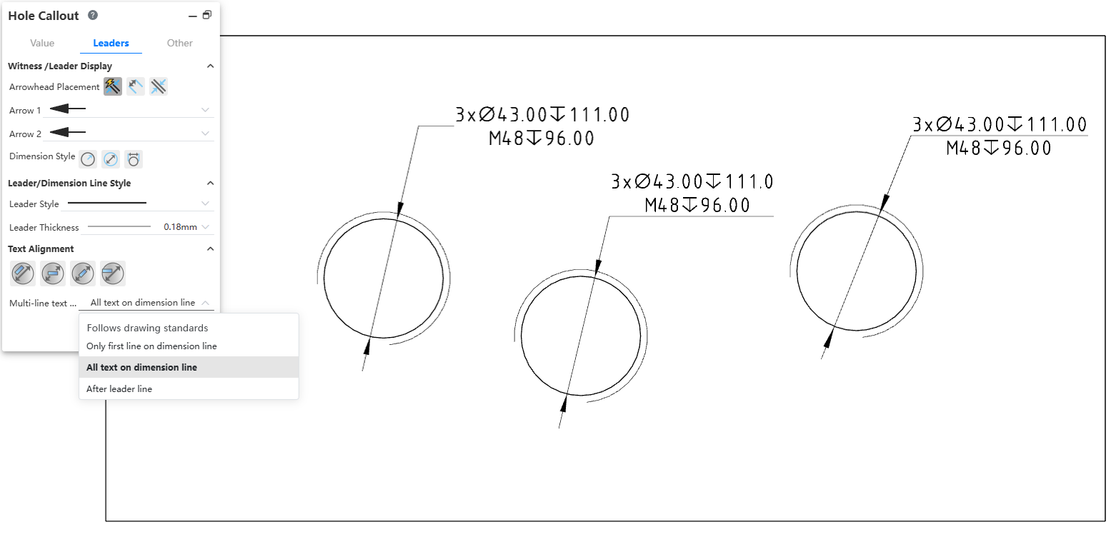
- Hole annotation supports custom text position and multi-line text position. Its text position defaults to being consistent with document properties and drawing standards, and supports manual switching of text position.