# Extruded Cut
When stretching a sketch, partially excise the stretched entity that intersects the excision body.
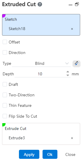
Click the toolbar  to open the Stretch Cut Command dialog box, and its command interface is shown in the following figure.
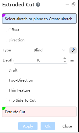
- Select a sketch or plane to sketch :
Pick a sketch profile to extrude the cut.
Pick a plane/datum plane, enter the sketching state, and after sketching and exit, automatically fill the drawn sketch into the pick box.
Note:
Sketches can contain multiple closed areas that do not intersect, distinguished from the Stretch Boss/Base command
- Offset: After checking, the offset mode drop-down box appears, and the stretching starts from the current sketch datum plane to the specified position. If necessary, point reverse.
- Bias method
(1) Distance: Enter the distance in the open Distance Modification dialog box and the stretch starts on a datum equidistant from the current sketch datum.
(2) From Surface/plane/datum: Pick up the starting surface in the open starting surface pick box, and the stretch is created from the selected surface and throughout the excision body.
【 Surface range: The plane and the base surface have an infinite range of action, and the surface's range of action cannot be extended 】
- Direction:After checking, open the direction pick box, the direction vector stretches the sketch in the direction perpendicular to the sketch outline, and if not selected, the direction is stretched according to the sketch method.
Note:
The direction vector can be a sketch line, two points, a solid edge line, or a reference reference line.
Method:Multiple options are available. Selecting a different type updates the corresponding parameters and previews different extrusion effects.
Draft:Stretch while forming a draft slope at a given angle.
Note:
Default outward draft, inward draft point reverse.
Direction 2: Performs extrusion in both directions based on the sketch plane. Multiple end conditions are available, which can be combined differently with Direction 1 to preview various extrusion results.
Thin-wall feature: After checking, the outline of the sketch can be thickened to generate a thin-walled entity and then excised.
- When the selected outline sketch has open loop lines, the thin-wall feature is checked by default;
- When all the selected contour sketches are closed-loop lines, thin-wall features are not checked by default;
Flip Side To Cut: See Flip Side To Cut for details.
Excised body: the body being excised by stretch. Support the simultaneous removal of multiple entities.
Note:
The excised body should intersect the stretched body.
# Blind
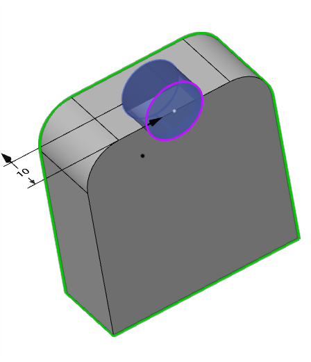
Depth: Stretches from the sketch plane to one side, adjusting the depth of the stretch by entering parameters or dragging the black arrow in the viewport. If necessary, point reverse.
Example: Given a depth mode, the excision effect is shown in the following figure::
# Up To Surface
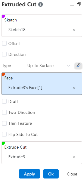
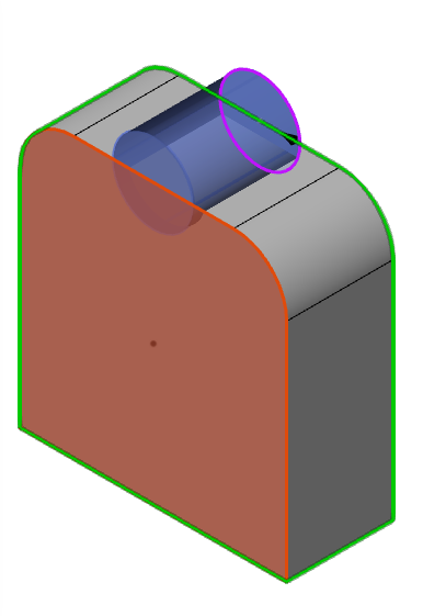
- Face:Select a face to extend to.
Note:
- Faces can be solid surfaces, planes, surfaces, or datums;
- The cylindrical or surface range needs to be larger than the sketch outline.
- Reverse:After the point is reversed, it is stretched in the opposite direction in the positive direction.
Example: In the shape-to-face mode, the extrusion and excision effect is shown in the following figure.
# Up to Vertex
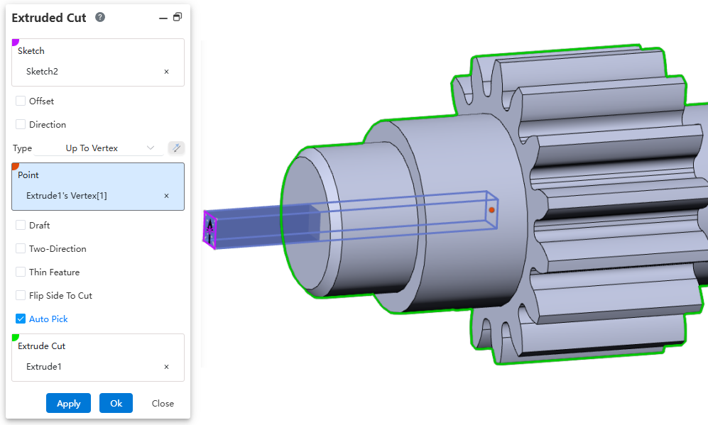
Vertex: Select a point. The extrusion feature terminates at an imaginary plane that passes through this point and is parallel to the sketch.
Example: Under the Up to Vertex end condition, the Cut Extrude effect is shown in the figure below:
# Up To Next
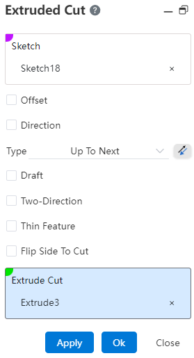
The resulting stretch cut feature automatically starts at the next plane outside the sketch until it runs through the entire cut body.
Example: Shape to the next side of the way, stretch cut effect as shown in the figure below.
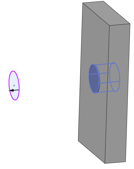
- Dialog box control description:
(1) Method: You can select Shape to Next. (This mode occurs only when there is a next side that meets the condition)
(2) Next side: The sketch is outside the solid outline and has a solid surface (either hidden or displayed) on which Boolean operations can be performed.
# Mid Plane
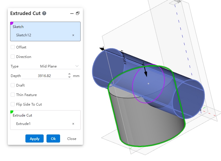
Depth:Symmetrically stretches to cut equal depths in both directions, using the sketch plane as a datum.
Example: The extrusion effect is shown in the following figure under symmetry on both sides.
# Through All
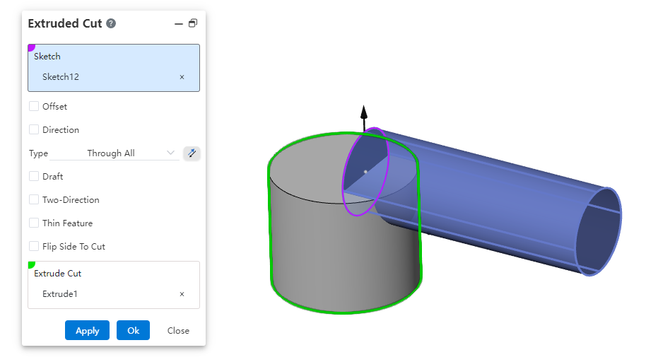
One-way through the current geometry, and when the point is reversed, it is extruded in the opposite direction of the preview direction.
Example: In the one-way penetration mode, the excision effect is shown in the following figure.
# Through All-Both
Completely cuts through the body on both sides of the sketch.
Example: Under the Through All - Both end condition, the Cut Extrude effect is shown in the figure below.
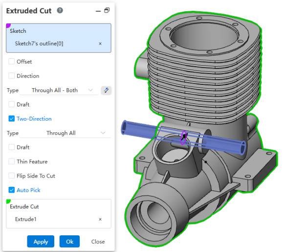
Note: When this option is selected, Direction 2 will be automatically checked and set to "Through All" (single side). You can manually modify the end condition to achieve other effects.
# Offset From Surface
Use this option when you need to maintain a certain distance from a surface.
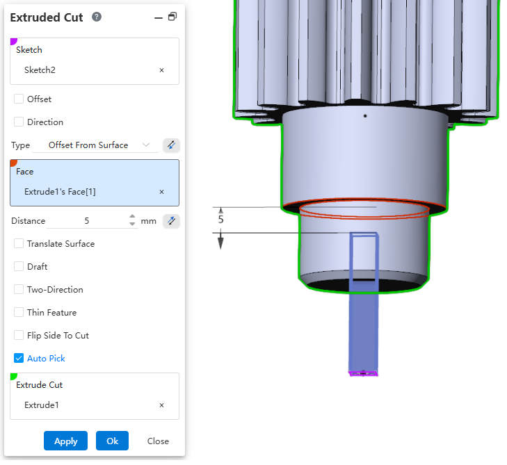
Dialog Control Description:
Type: Select "Offset from Surface". Click the reverse button behind it to change the extrusion direction.
Face: Select the specified face.
Distance: Set the offset distance. The supported input range is [0.00001, 10000000]. Supports variables and equations. Click the reverse button behind it to modify the offset direction.
Translate surface: When checked, the effect is a translated surface. When unchecked, the effect is an offset surface.
# Up To Body
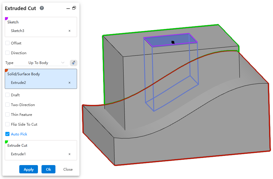
Usage:
Open the Extruded Cut command.
Select the sketch.
Set the option to "Up To Body".
Select the target body/surface.
Click OK to complete the creation.
# Two-Direction
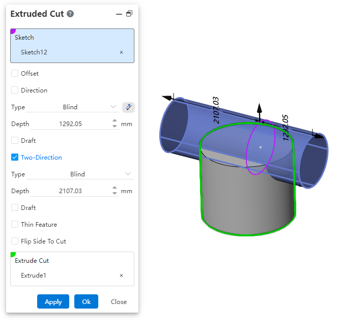
- After checking direction 2, use the sketch plane as the datum to perform a stretch cut in the other direction.
Note:
No direction 2 option is available when the drawing mode is selected for bilateral symmetry
- Type:Multiple options are available. Selecting a different type updates the corresponding parameters and previews different extrusion effects.
Example: The excision effect after checking direction 2 is shown in the following figure.
# Offset
When checked, the Biased Mode drop-down box appears and the stretch starts from the current sketch datum offset to the specified position. Dot reverse if necessary.
Bias method
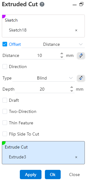
Distance: In the opened distance modification dialog, enter a distance. The extrusion starts from a plane offset from the current sketch plane at the specified distance.
From Surface/Face/Plane: In the opened start face selection box, pick a start face. The extrusion starts from the selected face.
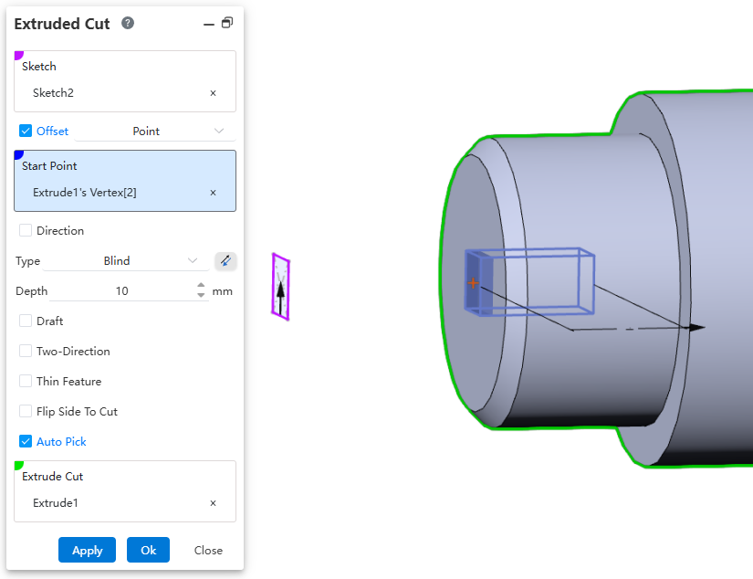
Point: In the opened start point selection box, pick a point. The extrusion starts from an imaginary plane created through the selected point and parallel to the sketch.
【 Surface range: The plane and the base surface have an infinite range of action, and the surface's range of action cannot be extended 】
Example:
- After setting the relevant parameters, the bias-distance effect is shown below.
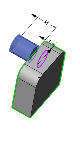
- After picking up the bias surface, the bias-distance effect from the surface/surface/datum is shown below.
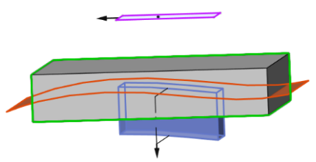
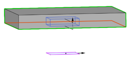
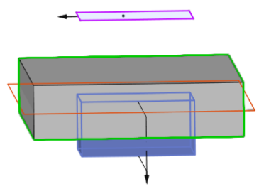
- After picking the start point, the effect of Offset - Point is shown in the figure below.
# Thin Features
See Thin Features for details.
# Flip Side to Cut
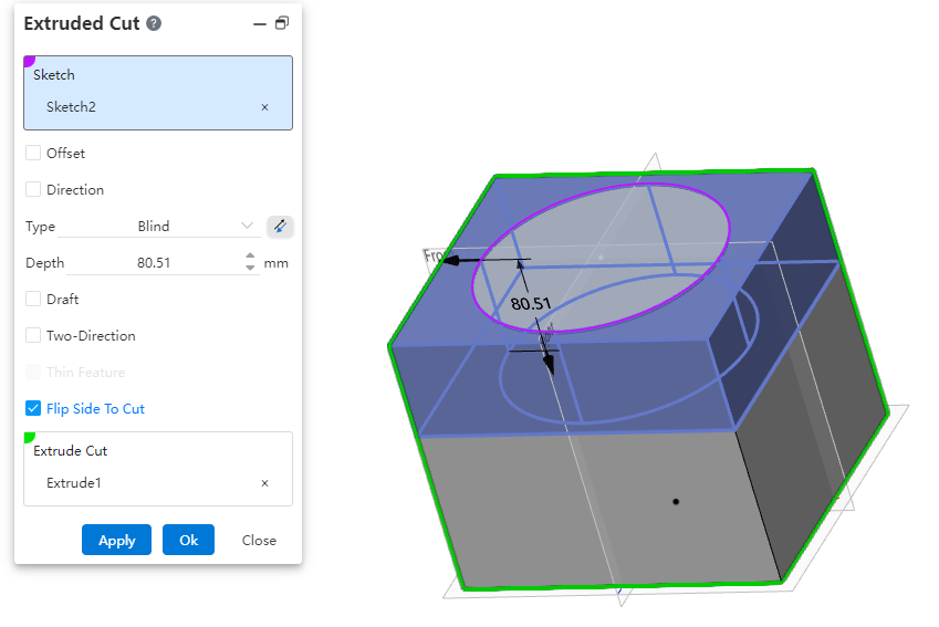
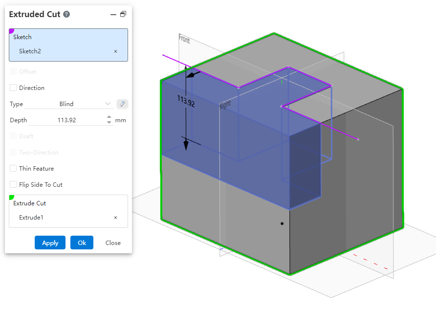
When it is not possible to remove the solid using an open contour or when you need to retain another part on one side, this option can be utilized to enhance design efficiency.
Closed contour: By default removes the area inside the closed profile. When 'Reverse Cut' is selected, it removes the area outside the closed profile, and the outer scope is unlimited.
Open contour: When selecting an open contour drawn on a solid face, if the contour divides the selected cut body into two parts, you can avoid using 'Thin Wall Features' and directly remove one side. When 'Reverse Cut' is selected, the other side will be removed.
Note 1: When selecting an open contour that is not drawn on a solid face, the reverse cut functionality cannot be used.
Note 2: When 'Thin Wall Features' are selected, the 'Reverse Cut' option is not available.
# Normal Cut
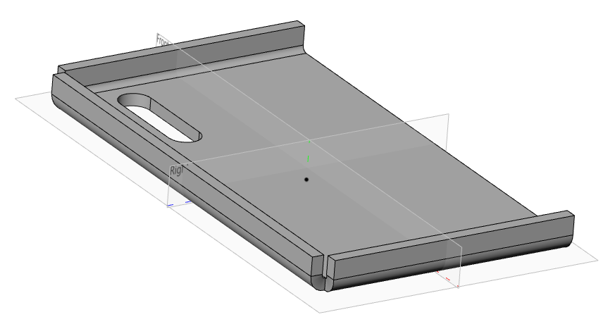
When performing an extrusion cut on a sheet metal body, selecting the orthogonal cutting option allows you to quickly generate a model aligned with sheet metal characteristics.
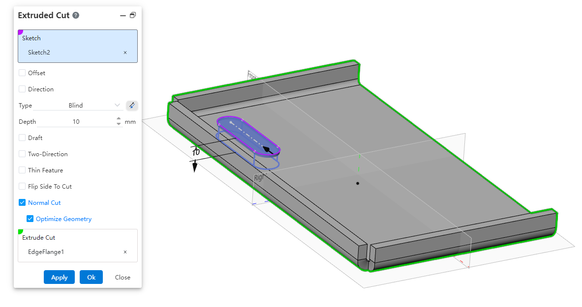
How to use:
1)Create the cut sketch and sheet metal body.
2)Open the Extrusion Cut command and select the sketch and sheet metal body;
3)Check the Orthogonal Cutting option;
4)Click OK to generate the cut feature with surfaces orthogonal to the sheet metal.
Note:
- The Orthogonal Cutting option is available only when performing a cut on a sheet metal body.
Select "Optimize Geometry" to smoothly connect the projections of the upper and lower surfaces of the removed portion, facilitating subsequent operations such as machining.
# Stretch cut equal to thickness
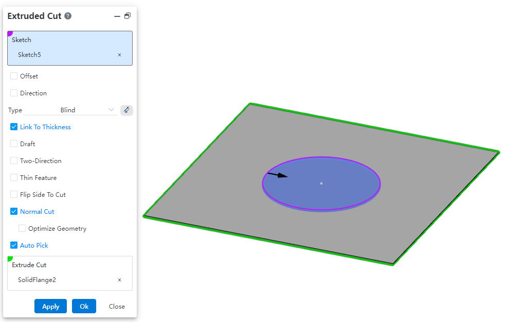
When extruding to cut a solid, using the "equal to thickness" option allows you to quickly create a cut with a depth consistent with the sheet metal thickness.
How to use:
Open the document containing the sheet metal body.
Open the Stretch Cut command.
Select the sketch and the feature to be cut.
Check the "Equal to Thickness" option; the depth of the stretch cut will automatically be set to the sheet metal thickness.
Click OK to generate the feature.
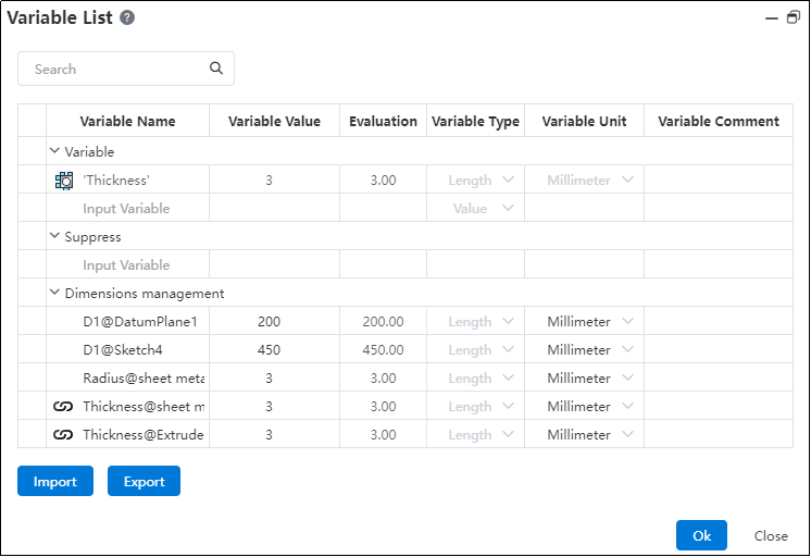
Note:After generating the sheet metal body, a "Thickness" variable with a sheet metal icon will appear in the variable manager, and the thickness of the cut will match the value of this variable.