# Data Translation
# Import
The system has been enhanced to support the following additional document formats during import:emp、emn、vda.
# Import- System Setting
Add a new setting under system configurations to enable the reading and extraction of coordinate points from design models created in various CAD systems, including Creo, NX (UG), CATIA, and SolidWorks. These extracted points can then be imported into the target system as "reference points" for alignment or other design purposes.
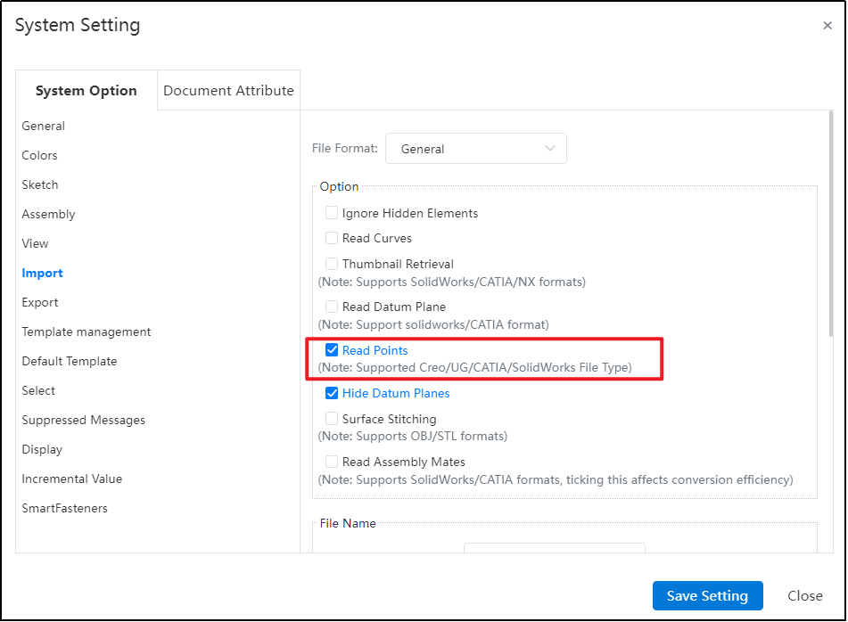
Note: The imported "points" function solely as references and cannot be edited once imported. These reference points are fixed within the system following importation and cannot undergo any further changes or modifications.
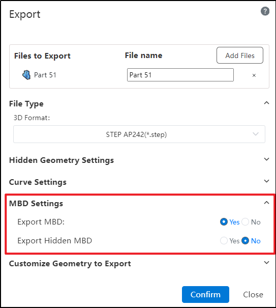
# Export stp242
Export added format 'STEP AP242 (*.step),During the export process, users now have the capability to determine whether MBD (Model Based Definition) information, including hidden MBD elements, should be included in the exported file. This feature provides greater control over the data output, facilitating precise and customized data exchange.
# Export Curves
The latest update introduces a new curve export functionality. This feature ensures you can simultaneously export curves along with your 3D model while providing the ability to set detailed parameters for these curves during the export process.
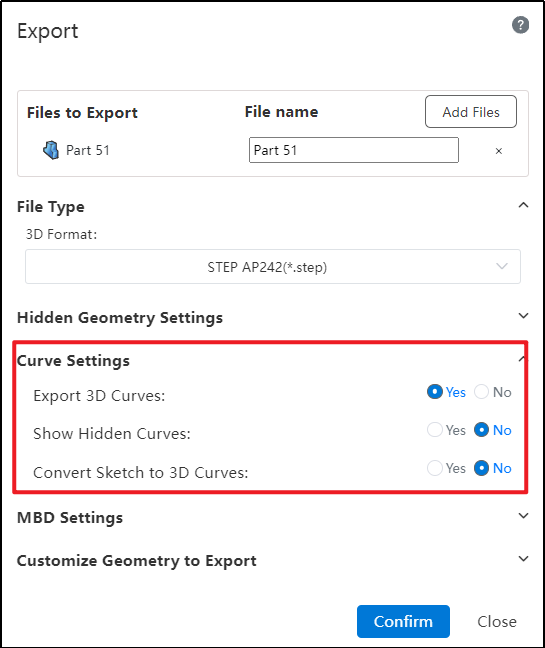
Dialog Box Controls Guide:
Exporting Spatial Curves: This setting allows you to determine whether spatial curves within a model are exported during the file export process. You can enable or disable this option based on your specific requirements.
Restoring Hidden Curves During Export: Hidden spatial curves, which are not visible in the model by default, can be converted to a displayed state when exporting. This feature lets you control whether these hidden curves should reappear in their original form once exported, ensuring that all relevant information is captured accurately.
Exporting Sketches as Spatial Curves: When dealing with sketches within your model, this control allows you to specify whether such sketches should be exported as spatial curves. Enabling this option means the sketch details will transfer over in the same manner as other spatial curves, preserving their geometric and associative properties for downstream applications.
Note:
Unsupported Curve Export Formats: Currently, the feature to export curves is not supported for files in the following formats: STL, OBJ, FBX, SLVX, and IFC.
Parasolid (x_b, x_t) Format Constraint: When exporting using the Parasolid format (extensions .x_b or .x_t), it is mandatory to select the option "Restore Hidden Spatial Curves to Displayed State". This ensures that hidden curves are made visible during the export process.
**IGES Export Behavior:**For Solid/Surface exports, hidden elements remain in their hidden state but are still exported;When exporting Components (Parts), hidden components will not be included in the output file.
Sketch Conversion for Spatial Curve Export: Conversion and export of sketches to spatial curves is only supported when the sketch is currently in its displayed (visible) state. Hidden or unselected sketches cannot be exported as curves under this feature.
# Export Rename
Added a new feature to rename files during export.
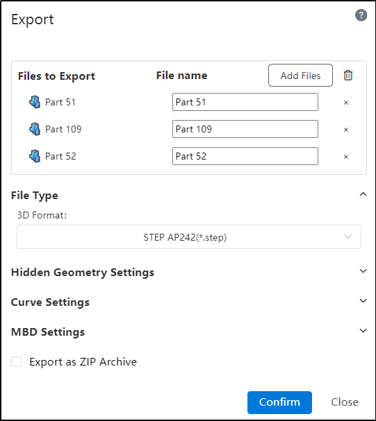
Usage Method:
1) Select the file you want to export.
2) Click on the text box below the filename and enter a new name.
3) Click "Confirm" to export the document with the custom name.