# Setting
# Display
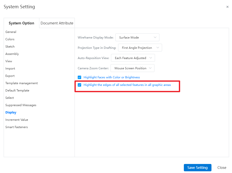
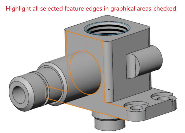
A new feature has been added to highlight the edges of all selected features in the graphical interface. Users can control whether selecting a face will also highlight the edges of its associated features.
Note:
- Checked, when selecting a face, both the face and the edges of the associated feature are highlighted in the viewport. Unchecked, when selecting a face, only the face is highlighted in the viewport, and the edges of the associated feature are not highlighted.

# Customize-Keyboard
Under the “Customize - Keyboard - Edit”menu, add the “Edit Feature”and “Edit Sketch”commands, supporting the customization of shortcuts for these functionalities.

How to use:
1) Under Customize - Keyboard - Editing, customize shortcuts for editing features and editing sketch commands.
2) Select the feature/sketch name or element in the Feature Panel or viewport.
3) Click the customized shortcut key to automatically enter the corresponding editing state for the selected feature or sketch.
# Image Quality
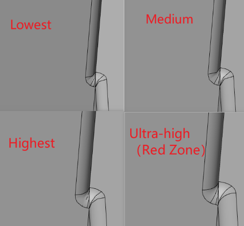
Added image quality setting functionality, supporting the configuration of model display quality, which impacts sub-pixel display, file size, and performance.
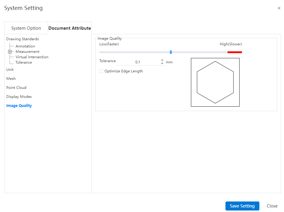
Note: The settings for this interface are saved only with the document and are not saved in the drawing standards.
Control Description:
- Error: Controls the actual maximum chord error. The smaller the value, the higher the display precision.
Optimize Edge Length (Higher Quality, Slower): When the error precision setting is at its minimum, selecting this option allows further improvement in image quality.
Apply to All Referenced Part Documents: Selecting this option applies the current assembly document's image quality settings to all referenced part documents, updating the part document's image quality settings to match those in the assembly. Only applicable to assembly documents.