# BOM
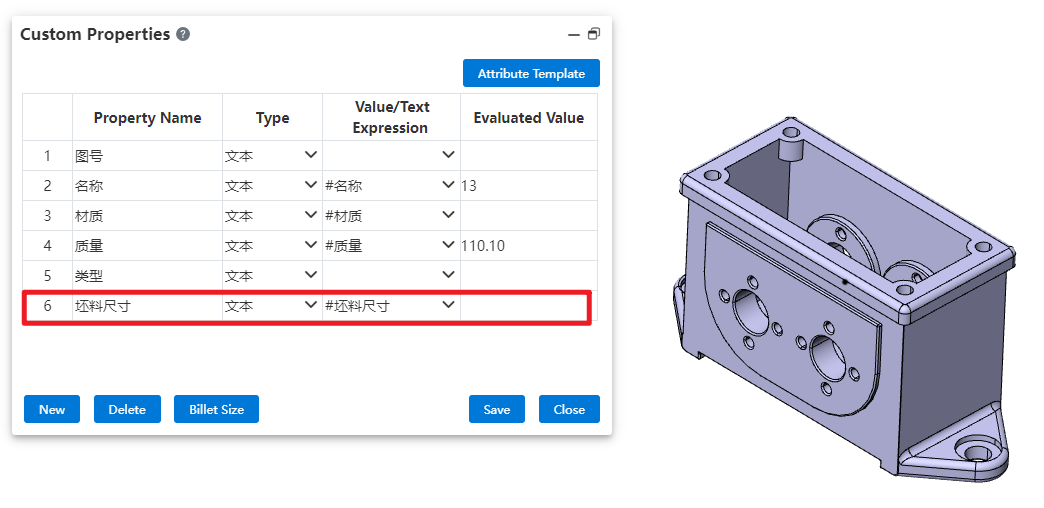
# Custom Properties
Added custom properties for blank size and blank calculation, which help guide the preparation of blanks before part processing.
Control Description:
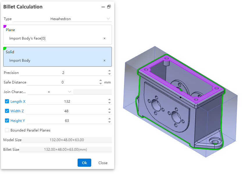
Type:Select the type of blank material, which can be either a hexahedron or a cylinder. Different types have different parameter items.
Plane:Choose the reference plane for creating the blank, which can be a solid plane, a curved plane, or a datum plane.
Precision:Control the display precision of the blank dimensions. You can manually input a number, adjust it using the mouse wheel, use increment/decrement keys, or enter a mathematical expression. Variables are supported.
Safety Distance:Adjust the amount added to the outer contour of the blank. The default value is zero, and both positive and negative values can be set.
Connection Character:Set the symbol used to connect the dimensions of the blank. Four types are provided, with the default being "×". You can choose from "×", "*", "-", or directly input any character.
Length/Width/Height:By default, these dimensions are automatically calculated based on the safety distance. You can manually input values, but after manual input, the safety distance will recalculate and revert to the automatically calculated values.
Bounded Parallel Plane:Control whether to create a parallel plane for the reference plane of the blank. If selected, the safety distance cannot be set, and the input fields for length, width, and height will be grayed out, preventing manual input.
Model Dimensions:Display the dimension parameters of the selected model after picking a plane or solid.
Blank Dimensions:Display the dimensions of the blank after the parameters are set.
How to use:
1) Click on BOM - Custom Properties to start the command.
2) In the numerical/text expression dropdown menu of any row, choose Blank Dimensions to display the current blank dimensions in the evaluated value field.
3) Click the Blank Dimensions button to begin the blank calculation process.
4) Select the type of blank calculation required
5) Choose the reference plane and relevant entities within the part for blank creation.
6) Adjust the display precision settings to control how blank dimensions are shown.
7) Specify the addition amount for the blank's outer contour.
8) Set the connection symbol used between blank dimensions (e.g., "×", "*", or "-").
9) Manually input or utilize automatically calculated values for length/width/height.
10) Determine whether to create a bounded parallel plane for the reference.
11) Click OK to complete the blank calculation. The new dimensions will be populated into the evaluated value field.