# Surfacec/Curves
# Conic
Added conic curve command, used to create conic curves.
How to use:
Click the "Conic Curve" command in the "3D Curve" dropdown menu.
Select the required elements: "Support Surface," "Start Point," and "End Point."
Other elements are optional and can be freely selected and combined as needed, such as "Start Tangent," "End Tangent," and "Control Parameter."
If the selected elements can generate a conic curve, the system will display a preview.
If there are too many constraints (over-constrained) or the selected elements cannot form a conic curve, the system will issue a warning.
Click "OK" to complete the creation.
Dialog Box Control Instructions:
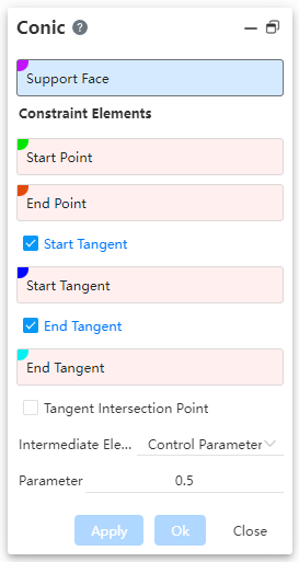
Support Surface: The surface on which the conic curve lies must be planar.
Start Point: The starting point of the curve.
End Point: The ending point of the curve.
Start/End Tangent: When checked, allows selecting the tangent at the start/end point.
Tangent Intersection Point: When checked, allows selecting the intersection point of tangents; in this case, start/end tangents cannot be selected.
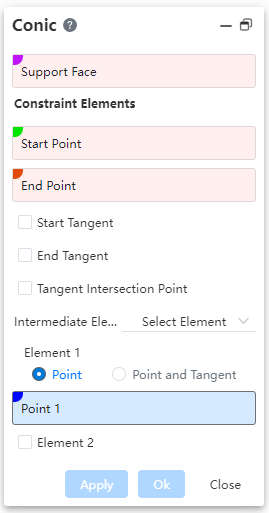
Intermediate Elements: Allows choosing the type of intermediate elements, with options including "Control Parameter" and "Selected Elements".
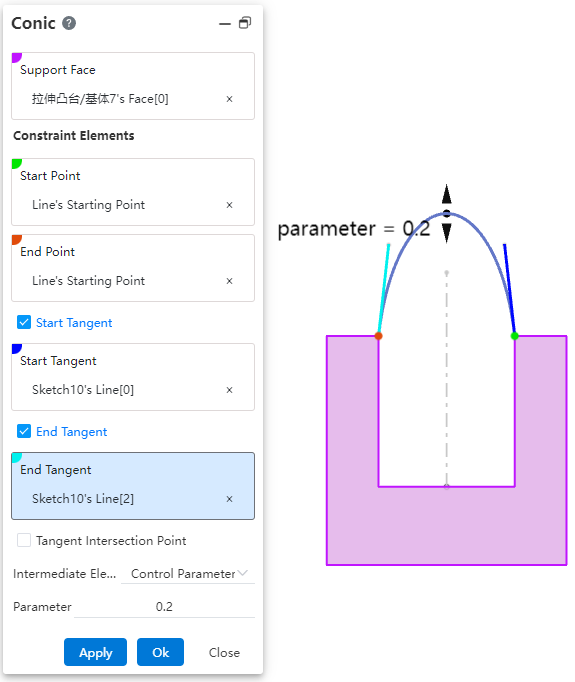
Control Parameter: By setting a "ratio" value, you can control the shape of the curve.
When the parameter is 0.5, the resulting curve is a parabola.
When the parameter is greater than 0 but less than 0.5, the resulting curve is an ellipse.
When the parameter is greater than 0.5 and less than 1, the generated curve is a hyperbola.
Select Elements: Control the curve shape by selecting through points on the curve.
Point, Point & Tangent: Choose to select only through points, or select both the points and the tangent direction of the curve at those points.
Element 2, Element 3: Check to enable selection of through points 2 and 3 on the curve.
Element illustration:
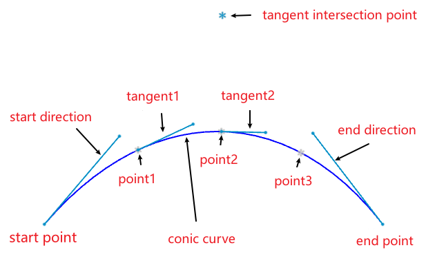
Note:The above figure merely illustrates the correspondence between elements and the curve. When using the command, simply pick some elements to fully constrain the curve, and the curve can be created.
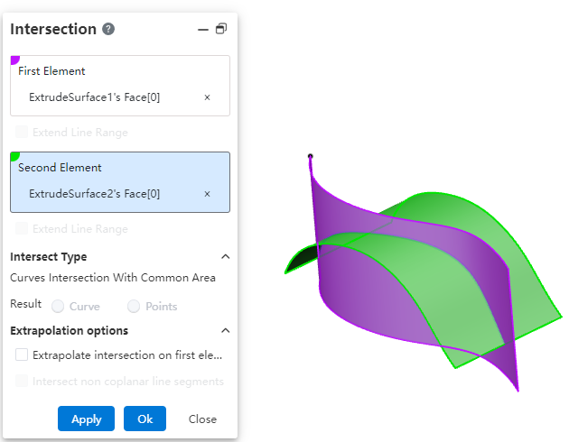
# Intersection
Added the Intersect command, used to create curves/points at intersection locations.
How to use:
Click the "Intersect" command in the "3D Curve" dropdown menu.
Select the first and second elements to be intersected, respectively.
Modify the options as needed.
Click OK to create the intersection curve/point.

Dialog Box Control Instructions:
First/Second Element: The two elements to be intersected, supporting lines and surfaces.
Extend Linear Intersection to Surfaces: When the intersecting elements do not have an actual intersection region, enabling this option will virtually extend the elements to generate an intersection. This only applies to lines.
Curve Intersection Result with Common Region: When two curves have a completely overlapping segment, this option controls whether the result is the overlapping segment or its endpoint(s).
Extend Intersection Beyond First Element: When two surfaces intersect and the second surface is smaller than the first, enabling this option extends the intersection curve beyond the boundary of the first surface.
Intersect Non-Coplanar Line Segments: For non-coplanar line segments, enabling this option creates the midpoint at the shortest distance between the two lines.
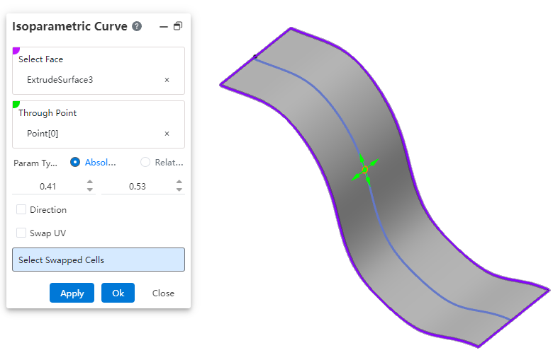
# Isoparamatric Curve
Add a new parameter curve command to create curves on a surface that are aligned with the isoparametric direction.
How to use:
Click the "Isoparametric Curve" command in the "3D Curve" dropdown menu.
Select a surface.
Specify a point on the surface through which the isoparametric curve will pass.
Set the options and parameters as needed.
Click OK to complete the curve creation.
Dialog Box Control Instructions:
Surface: Select the surface on which to create the isoparametric curve.
Through Point: Click on the surface to specify the point that the isoparametric curve will pass through. The direction of the curve is influenced by the mouse movement when specifying this point.
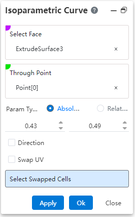
Parameter Type: Controls the type of parameter for the through point's position.
Absolute: The parameter of the through point relative to the absolute origin.
Relative: The parameter of the through point relative to the relative origin. The relative origin defaults to coinciding with the absolute origin. Click the "Reset Origin" button to move the relative origin to the current through point.
Actual Length: Available only when the parameter type is "Relative"; displays the actual distance between the through point and the relative origin.
Direction: Check this option to pick a line to define the UV direction of the surface.
Swap UV Direction: Check this option to swap the UV directions of the surface.
Select Exchanged Face: For a surface composed of multiple patches, select a patch here to change the extension direction of the curve on that patch.

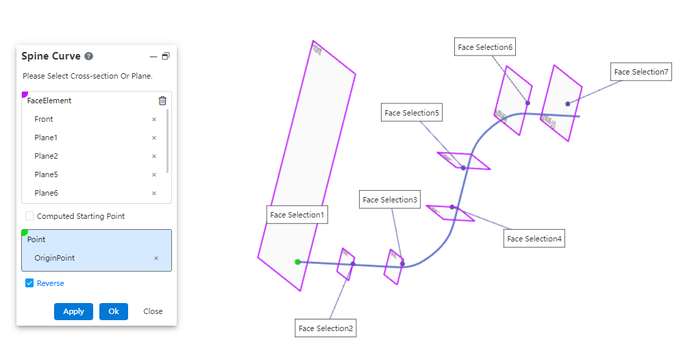
# Spine Curve
Added the "Spine Line" command, used to create curves perpendicular to a sequence of ordered planes or planar curves.
How to use:
Click the "Spine Curve" command in the "3D Curve" dropdown menu.
Select the faces that the spine curve will pass through, in sequence.
Choose the starting point as needed and modify the relevant options.
Click OK to complete the curve creation.
Dialog Box Control Instructions:
Face Elements: Select the planes or sketch profiles that the curve will pass through, ensuring they are picked in the correct sequence.
Computed Start Point: The start point is automatically set based on the first selected element.
Select Start Point: Manually pick a point to define the starting point of the curve.
Reverse Direction: Reverse the direction of the curve from the first face.
# Smooth Curve
Added the Fair Curve command, used to make existing curves smoother.
How to use:
Click the "Fair Curve" command in the "3D Curve" dropdown menu.
Select the curve you want to smooth.
Set the parameters and options as needed.
Click OK to complete the curve smoothing.
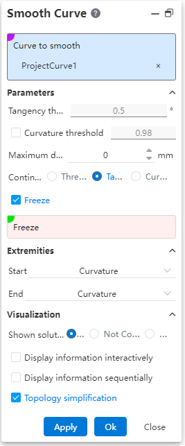
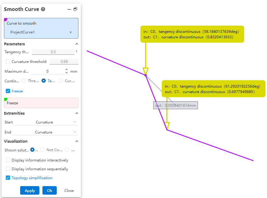
Dialog Box Control Instructions:
Curve to Fair: Used to select the curve that needs to be smoothed.
Tangent Threshold: Sets the tangent discontinuity threshold. The system will smooth the curve within this threshold range. Effective only when the "Continuous Threshold" option is selected.
Curvature Threshold: Sets the curvature discontinuity threshold. The curve will be smoothed within this threshold range. Effective only when "Continuous Threshold" or "Tangent" mode is selected and this option is checked.
Maximum Deviation: Sets the maximum allowable deviation between the original curve and the smoothed curve.
Continuity: Selects the correction mode for smoothing.
Freeze: When checked, allows you to select vertices or edges that should not be smoothed.
Start/End Continuity: Sets the continuity conditions at the start/end points of the smoothed curve and the original curve, respectively.
Displayed Information: Choose what information to display on the smoothed elements in the viewport.
All: Displays all information.
Unresolved: Shows information about discontinuities that were not corrected or preserved.
None: Displays no information.
Interactive Display: When checked, only display information arrows; information appears only when hovering the mouse over the arrow.
Sequential Display: When checked, use "Previous", "Next", or input a sequence number to control which information is displayed.
Topological Simplification: When checked, automatically removes vertices at curvature-continuous locations to reduce the number of segments in the curve.
← Features Sheet Metal →