# Simulation
In the CrownCAD 2025 R3 release, the first structural simulation module allows you to perform structural simulation calculations in part documentation.
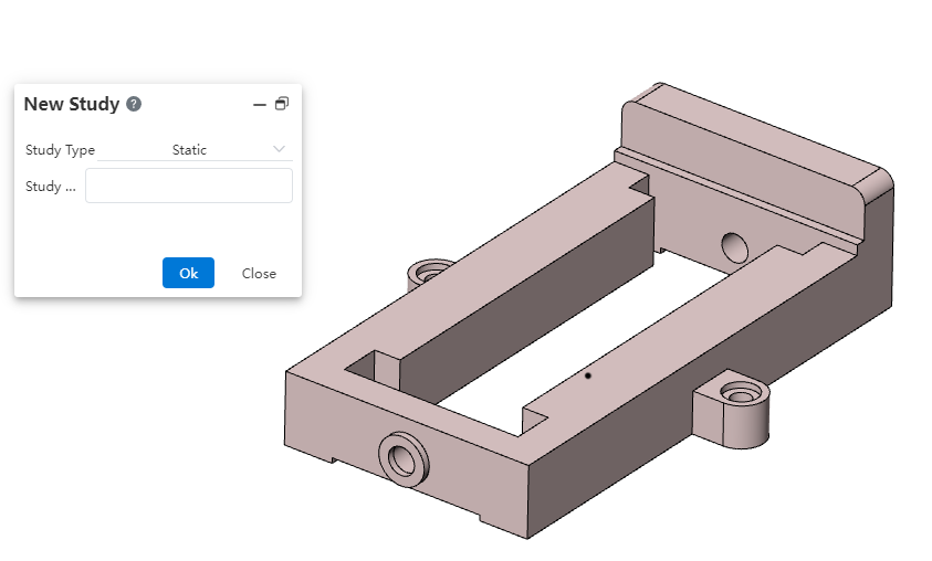
# New Study
Switch the toolbar to the "Simulation" module, click  the icon to create a new example and enter the name of the example:
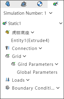
# Set The Entity You Want To Analyze
When multiple entities are included in a document, all entities in the document are analyzed by default;
Right-click an entity in the simulation panel to set whether it wants to be analyzed;
Then edit the model to generate a new entity, the new entity is the entity to be analyzed by default;
The entity set to not analyze is not visible when the example is activated, and it does not need to consider whether it has added material, external load, and boundary information during calculation.
# Edit Material
Select the entity in the simulation panel, click Apply Material  and set the selected entity to the selected material;After setting, you can view the material set by the current entity in the simulation panel.
Note:
When the example is created, each entity inherits its material in the part document by default. Entities that do not have a separate material set inherit the document material.
After the example is created, the material of the entity in the example can be modified by the "Apply material" command of the simulation module.
The same entity can set different materials in different examples. Setting the material in the example does not affect the material of the entity.
A material must be added to each entity to be analyzed.
Do not select the entity, directly use the application material function, will uniformly modify the material of all the entities in the example.
# Set External Load
Start the external payload  command, select the payload element and payload type, and add an external payload to the entity.Right-click the external load of the simulation panel, you can set the visibility of the load arrow in the viewport.
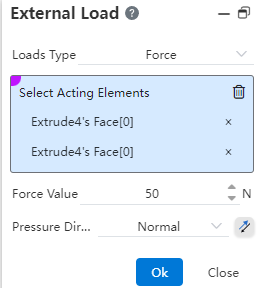
Load type supports "force, torque, pressure, gravity, centrifugal force, remote load/mass".
- Force: Can act on "points, lines, surfaces". Acting on the "surface", the load direction supports the "normal, direction vector" type; Acting on the "point and line", the load direction only supports the "direction vector" type.
- Torque: Acting on the "surface", it is necessary to pick up the "cylinder, straight edge line" as the torque axis.
- Pressure: acting on the "face", the load direction supports the "normal, direction vector" type.
- Gravity: Acts on the "body", gravity direction is specified by picking up elements, gravity magnitude can be set to Earth gravity or custom values.
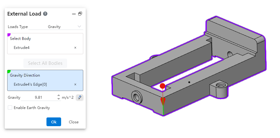
| Name | Rules |
| Type of load | Display and select the load type |
| Pick up body | Pick up the entity, multiple can be selected |
| Select all entities | Click to fill all entities into the pick up body pick box |
| Gravitation Direction | Can pick a plane, a straight line, two points to specify the direction of gravity.Points, lines and surfaces can be taken from sketches, solids, surfaces, and reference elements |
| Gravity | Input range [-1e7,1e7].Equations and variables that do not support linkage.Click the rear reverse button to reverse |
| Apply Earth gravity | Unchecked by default. After this parameter is selected, the gravity value cannot be changed. The value is fixed to 9.81 |
- Centrifugal force: acts on the "body", the axis of centrifugal force is specified by picking up the element, and the angular speed can be customized.
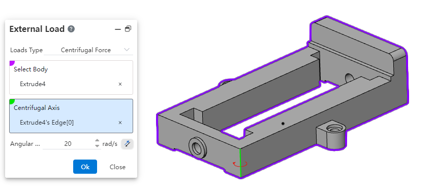
| Name | Rules |
| Type of load | Display and select the load type |
| Pick up body | Pick up the entity, multiple can be selected |
| Centrifugal axis | Can pick up a cylinder, a straight line, two points to specify the centrifugal axis.Points, lines and surfaces can be taken from sketches, solids, surfaces, and reference elements |
| Angular Velocity | Input range [-1e7,1e7].Equations and variables that do not support linkage.Click the rear reverse button to reverse |
- Remote load/Mass: Acting on the "face", you can specify the load position and the amount of shift/rotation.
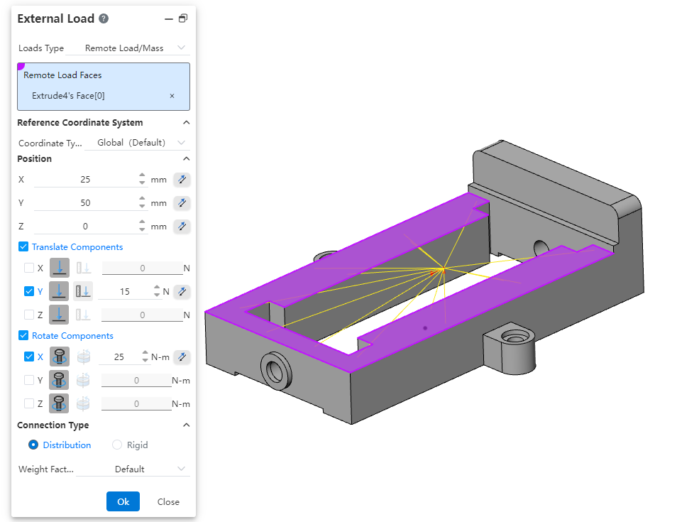
| Name | Rules |
| Type of load | Display and select the load type |
| The face of the remote load | The surface of a pickable entity supports multiple selections |
| Reference coordinate system | Control the expansion and folding of relevant options |
| Type of coordinate system | Optional "Global (default), User Defined" |
| Reference coordinate system | Displays this only if the coordinate system type is set to user-defined.Single select a reference coordinate system |
| Position | Control the unfolding and folding of relevant options |
| X、Y、Z | Range can be entered [-1e7,1e7].Equations and variables that do not support linkage.Click the rear reverse button to reverse |
| Pan parts | Control the unfolding and folding of relevant optionsBy default, it is not selected and folded, and the parameters can be set if only selected |
| XYZ | Check the pan that represents the direction that needs to be set accordingly |
| Pan type | "Force, shift" from left to rightUnselected directions Grey this item |
| Translation parameter | The unit is N for force selection and mm for conversion selection. Click the reverse button at the back to reverse. Unchecked directions do not show this. 可输入范围[-1e7,1e7]。 Range can be entered [-1e7,1e7].Equations and variables that do not support linkage. |
| Rotating parts | Control the unfolding and folding of relevant options. Control the unfolding and folding of relevant optionsBy default, it is not selected and folded, and the parameters can be set if only selected. |
| XYZ | Checkboxes represent rotations that need to be set in the corresponding direction, none is selected by default. |
| Type of rotation | "Torque, Spin" from left to rightUnselected directions Place ash on this item. |
| Rotation parameter | When selecting torque, the unit is N-m, and when selecting rotation, the unit is °. Click the back reverse button to reverse. Unchecked directions do not show this. Enter the range [-1e7,1e7].Equations and variables that do not support linkage. |
| Type of linkage | Control the expansion and collapse of related options |
| Connection types | Optional "Distributed, rigid" |
# Set Fixture
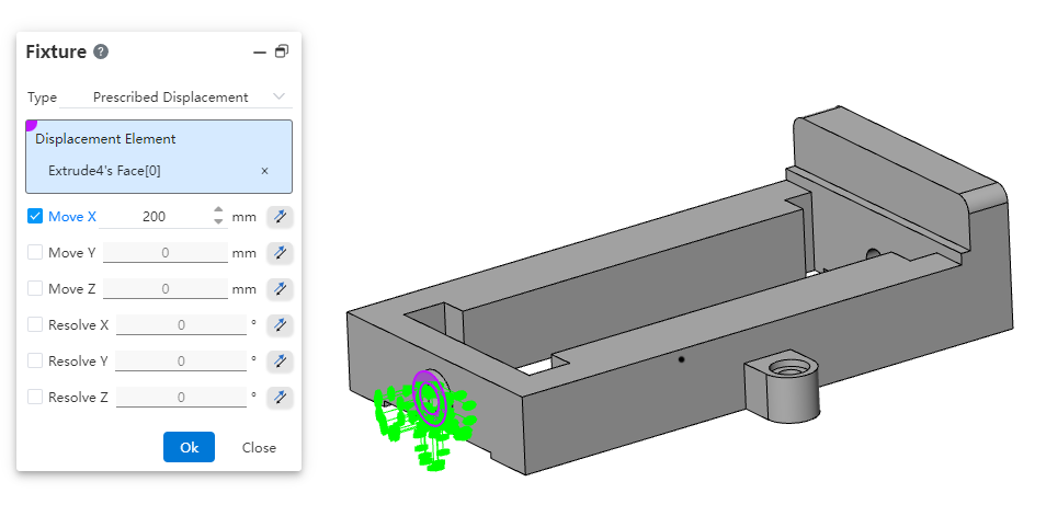
Click  , start the boundary constraint command, select the boundary constraint action element and type, add a boundary constraint to the entity.Right click on the boundary constraint of the simulation panel, you can set the visibility of the constraint arrow in the viewport.

The boundary constraint supports the type of "fixed geometry, symmetry, specified displacement".
- Fixed geometry: Acts on a point or line surface to hold the selected element in place.
- Symmetry: Only one half of the model is modeled, the plane of symmetry is specified, and the other half of the model is deduced by symmetry.
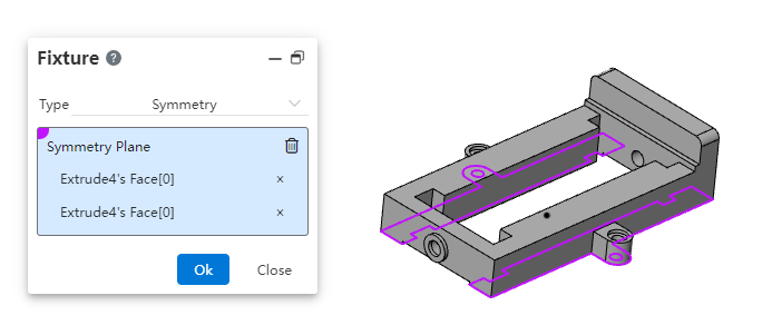
- Specify displacement: Sets the amount of translation/rotation of the selected element, this constraint can also be used as a load.
| Name | Rules |
|---|---|
| Type | Display and select the boundary constraint type |
| Displacement element | Pick up any number of vertices, edges, surfaces.Point line surface can be taken from solid, surface. |
| XYZ translation/rotation | Only the checked items can set rear parameters. |
| XYZ Pan/rotate | Range can be entered [-1e7,1e7].Equations and variables that do not support linkage.Click the rear reverse button to reverse. |
# Set Connection
If you want to create a linkage between entities, you can add contacts using the Connect command.
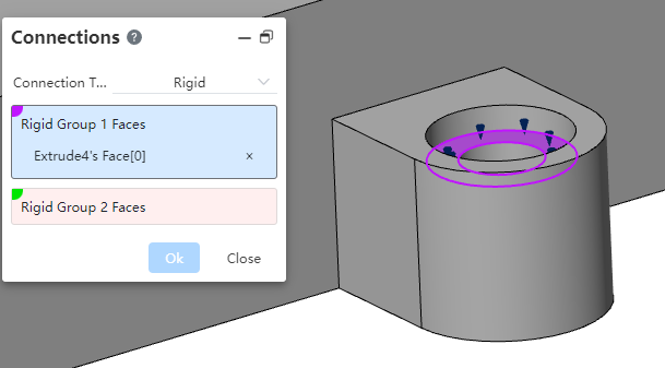
Connections support the "rigid, bind, spring, link" type.
Rigid: The surface to which the "rigid connection" is added is treated as a "rigid body" that does not deform when analyzed, and the two sets of surfaces move together and are stressed together.
- The two sets of faces should come from two entities
- The faces must be from the entities included in the analysis
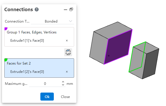
Binding: The selected elements are treated as if they were welded during the simulation.
| Name | Rules |
|---|---|
| Type | Display and select the local interaction type |
| Faces, edges, vertices for group 1 | Choose multiple points, lines and surfaces from the entity |
| Swap interaction surfaces | Click to swap interaction surfaces |
| Faces of Group 2 | Choose more than one face from the entity |
| Automatically switch source and target entities to get the effect of changing | Checked by default |
| Maximum gap | The default value is 0. The value can be in the range of 0,100.Equations and variables that do not support linkage. |
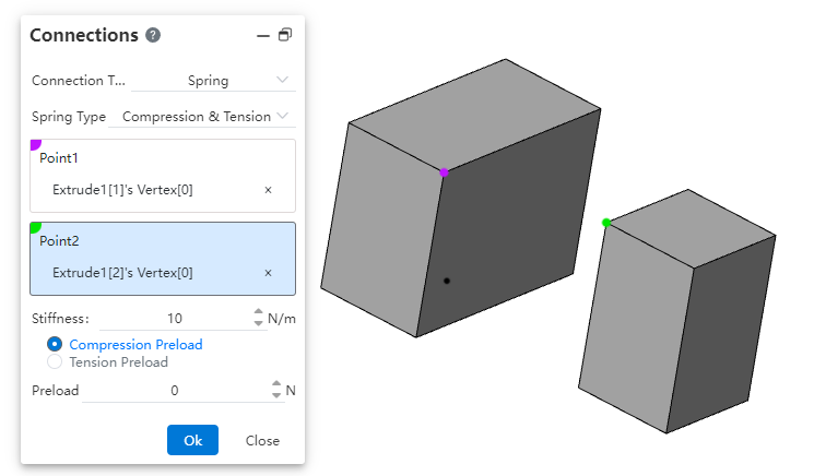
- Spring: Defines a spring that resists tension only, compression only, or both.
| Name | Rules |
|---|---|
| Type | Display and select connection type |
| Spring type | Optional "Compress only, stretch only, compress & Stretch" |
| Dot 1, dot 2 | Pick up vertices that belong to different entities. Single pick. |
| Stiffness | Input range [-1e7,1e7].Equations and variables that do not support linkage. |
| Type of preload | Compressive preload can only be selected for compression, tensile preload can only be selected for tension, compression and tension can be selected for one of the two. |
| preload | Input range [-1e7,1e7].Equations and variables that do not support linkage. |
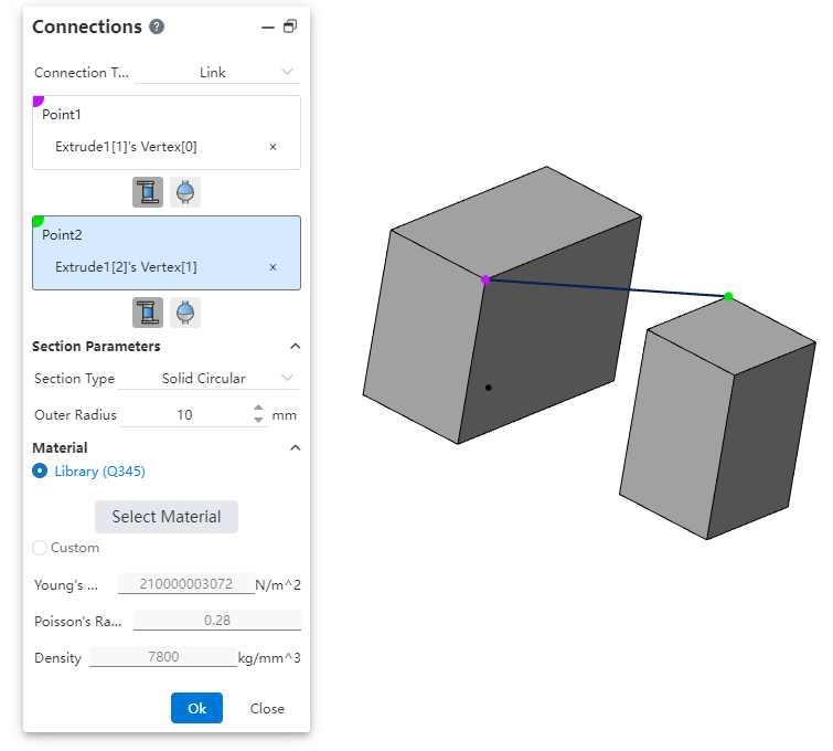
- Connecting rod: Defines the connecting rod joint between two parts.
| Name | Rules |
|---|---|
| Type | Display and select connection type |
| Dot 1, dot 2 | Pick up vertices that belong to different entities. Single pick. |
| Conjugation Type | "Rigid, ball hinge" from left to right. |
| Section parameters | Control the unfolding and folding of relevant options |
| Type of section | Optional "Hollow section, solid section" |
| Outside radius | Inputable range [0.001,1e7].Equations and variables that do not support linkage. |
| Inner radius | Show this when hollow section only.Range can be entered [0.001,1e7].Equations and variables that do not support linkage. |
| Materials | Control the unfolding and folding of relevant options |
| Material assignment mode | Optional "Library, Custom" |
| Select materials | Available when selecting "Library" only, click to pop up the Material Library dialog box for setting materials. The material name you set is displayed after "Library". |
| Young's modulus | Input range [-1e7,1e12].Scientific notation should be supported.Linkage equations and variables should not be supported. |
| Poisson's ratio | Input range [-1,1].Equations and variables that do not support linkage. |
| Density | Input range [0.001,1e7].Equations and variables that do not support linkage. |
# Set Mesh
Use the "Global Grid, Local grid" command to set the grid parameters.
There are only 1 global grid parameters, and you can add more than one local grid parameter.
Control parameters are optional. You can directly generate the grid with default values without adding them.

| Name | Rules |
|---|---|
| Maximum mesh size | Range available [0.001,1e10].Equations and variables that do not support linkage. |
| Minimum mesh size | Input range [0.001,1e10].Equations and variables that do not support linkage. |
| Circle minimum number of units | Integers in the range [3,50] can be entered, and non-integers are automatically rounded.Linkage equations and variables are not supported. |
| Minimum number of side units | Integers in the range [1,50] can be entered, and non-integers are automatically rounded.Linkage equations and variables are not supported. |
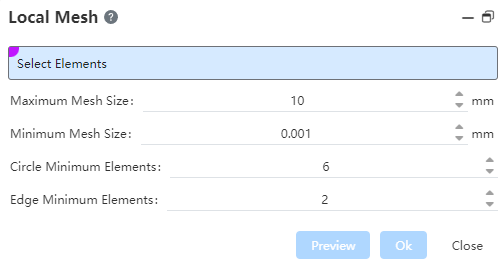
| Name | Rules |
|---|---|
| Select elements | Multiple edges and surfaces from the entity can be selected. |
| Maximum mesh size | Range available [0.001,1e10].Equations and variables that do not support linkage. |
| Minimum mesh size | Input range [0.001,1e10].Equations and variables that do not support linkage. |
| Circle minimum number of units | Integers in the range [3,50] can be entered, and non-integers are automatically rounded.Linkage equations and variables are not supported. |
| Minimum number of side units | Integers in the range [1,50] can be entered, and non-integers are automatically rounded.Linkage equations and variables are not supported. |
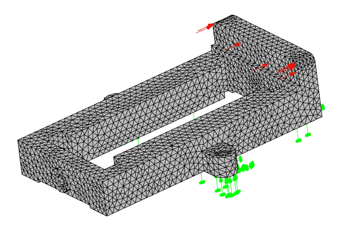
# Generating Mesh
Click  to start the Generate Grid command, or right click on the grid in the simulation panel - Generate Grid and click OK after setting the precision in the dialog box.
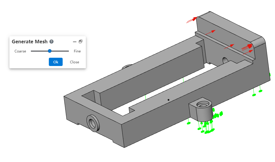
Note:
- You can manually generate a grid for the entity before running the example;
- When running the example, if the grid has not been created yet, or if the grid is inconsistent with the current entity, the grid is automatically created or updated with medium precision.
# Run
Click to  execute the Run this example command.
When running the example, the specific information is displayed in the dialog box. And support to click "terminate" to end the calculation. Deselect "Show resolver status when running analysis" to hide specific information.

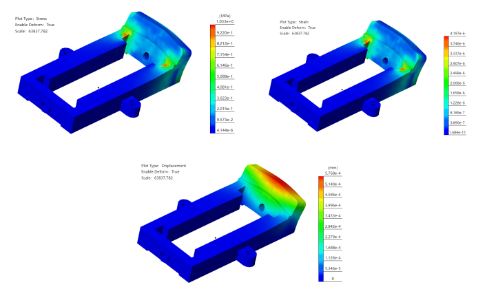
# View Results
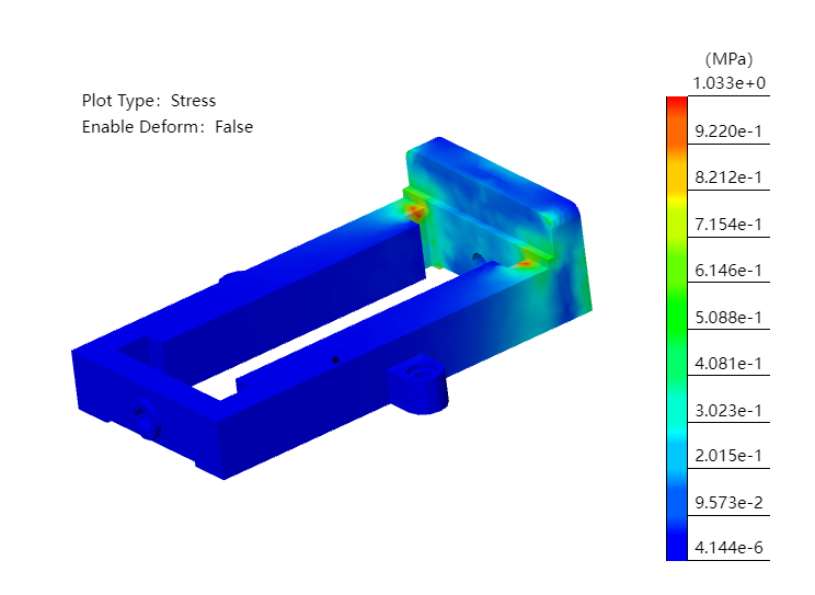
- The "stress" result will be displayed by default after the calculation is complete.
- Double-click on "Stress/Strain/Displacement" in the simulation panel to toggle the display results.
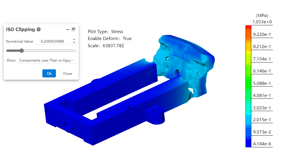
# Deformation Results
- By default, the model will be deformed, and the degree of deformation will be increased in proportion to observe the displacement effect.
- Click
 on the command bar to turn on or off the model deformation effect.
 - Right-click the result of "Stress/strain/displacement" in the simulation panel, click Set, and change the setting mode to "Custom", you can modify the amplification ratio of deformation effect.

# ISO Clipping
- Click
 on the command bar's so that the result shows only areas of the model that match the parameters.
# Animate
When any result is displayed in the example, click the [animation] command to play the resulting animation.

- You can use the animation controller to control animation playback, pause, etc.
- Click the Export button to export the animation as a video.
# Create Report
- Click
 on the command bar to bring up the Report Options dialog box where you can select what you want to include in the report.
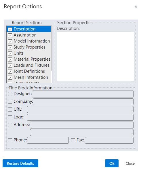
What can be included:
| Sections | Content |
|---|---|
| Title | Set the designer, company, etc. information as needed |
| Instructions | User defined text |
| Hypothetical | User defined text |
| Model information | All references cite information such as the names of parts and sub-assemblies |
| Example properties | Including example name, analysis type, and grid type of solving information |
| Units | Unit system: · Length/displacement · Temperature · Angular speed · Stress/pressure |
| Material properties | · Material details such as name, yield strength, tensile strength · Material table values and diagrams · Customize the material description information · Custom material properties defined by the user for the custom material |
| Loads and fixtures | · Load name, image and details |
| Joint definition | · Joint type and details· Joint force |
| Grid information | · Grid details and images· Grid control information (name, image, and details) |
| Example results | Image and parameters of the result. |
| CONCLUSION | User defined text. |
| Addendum | Support for selecting local files, insert into documents. |
1) The "Title" section checks and adds information in the title information.
2) "Title - Logo" requires the user to upload a picture.
3) The "Description, Hypothesis, Conclusion" section requires custom text to be entered by the user, which is blank by default.
4) Comment text can be added to other sections, and comment text is added at the end of the entire section.
- Click OK after selecting the content to start generating the report, which will be downloaded automatically once generated.
- The report generation process cannot be stopped, and other operations are prohibited.

# Active and Exit Case
utomatically activate after creating a new calculator.
Double-click the example in the simulation panel, or right-click the example and select "Activate Example" option to activate the example manually.
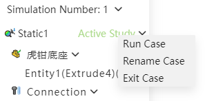
Right-click an already activated example and select the "Exit example" option to exit the currently activated example. It is recommended that you exit the example before editing the model.
Manually switching between "Feature Panel, View Panel, Simulation panel" does not affect the activation state of the example, that is, switching the panel does not cause activation or exit of the example.
After the example is created, modifying the model does not affect the generated example. You can activate the example to view historical data, or reset the example parameters and calculate the result.