# Layer Manager
Create, manage, and delete layers. Manage the display, color, line and other parameters of views, annotations and other elements in batches through layers.
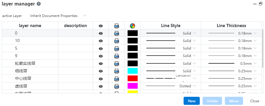
Layer manipulation:
New layer: Click the Layer Manager command in the comment module. Click the New button, set the layer name and parameters, click in the blank space to finish the new layer.
Delete the layer: Click the Layer Manager command in the annotation module. Select the layer you want to delete, click Delete, the confirmation dialog box will pop up to confirm and delete. You are not allowed to delete a layer that is currently in use.
Manage layers: Click the Layer Manager command in the comment module. Click on the layer parameter you want to modify to make changes.
Activate the layer: Click the Layer Manager command in the annotation module. Select a layer from the Active Layer drop down menu. The selected layer is the default layer for the new element. Optionally, "None, Follow Document properties, Layers 1, 2, 3..." .
- None: The new element belongs to the empty layer.
- Follow Document Properties: The new element belongs to the default layer set in the system Settings for that element - Document Properties. If the element does not have a corresponding system Settings interface, or if the default layer in Document properties is none, then the new element does not belong to any layer.
- Layer 123...: The new element belongs to the layer selected here and the layer name should be displayed.
Modify the layer to which the element belongs: Click the Layer Manager command in the comment module. Select the element you want to modify in the viewport, select the target layer in the dialog box, and click the Move button.
The parameters and effects of the layer
| Parameters | Action | Remarks |
|---|---|---|
| Name | Distinguish layers | Double names are not allowed |
| Instructions | Add the layer's explanatory information as needed | |
| Revealing | Controls the hidden state of elements belonging to this layer | |
| Controls whether elements belonging to this layer print | Hidden layers force not to print | |
| Color | Control the color of the elements that belong to this layer | |
| Line Lines | Controls the lines of the elements that belong to this layer | |
| Line width | Controls the line width of elements that belong to this layer |
- The elements that the layer controls, and what parameters control those elements
| Elements | Control parameters |
|---|---|
| Sketch non-constructed lines | Implicit, print, color, line type, line width |
| Sketch construction lines | Concealment, printing, color |
| Dimensional labeling | Explicit, print, color |
| Annotation, part serial number, surface roughness, welding symbol, form and position tolerance, reference, reference target, revision cloud, revision symbol, center symbol line, center line and other annotation elements | Implicit, print, color |
| Section Lines | Salient, print, color, line width |
| Forms of all kinds | Explicit, print, color |
Note:
| |
- Sketch color: The sketch in the engineering drawing has two color states, "Show the sketch constraint state color, show the color of the layer to which the sketch belongs". Switch through the "Show Constraint State Color" button in the leading view toolbar.

- Project drawing export DWG, DXF: You can choose whether to export hidden layers. Unlayered elements are automatically exported to "Layer 0".