Welcome to CrownCAD 2023 R3
The main enhancements of CrownCAD 2023 R3 are improvements to existing products and offer new and innovative features.
| Application | Enhances the display of part boundaries and decorative thread lines in section view |
| New part, assembly, and drawing documents can be opened in a new window | |
| Support full screen/cancel full screen | |
| The value input box can be adjusted by mouse wheel or up and down arrow | |
| Sketch | Circles/arcs support radius/diameter switching and Max/min size |
| Insert dwg file directly as sketch element to participate in modeling | |
| Change sketch planes | |
| Right mouse button as quick OK key | |
| Right mouse button as quick OK key | |
| Part and feature | Rotation features automatically identify the rotation axis, and the rotation axis type expands |
| Supports the creation of two-plane midplane | |
| Add PI function in variable management | |
| Quality attribute adds model matrix information | |
| Curves | Add decorative thread line function |
| Weldment design | Enhances group path selection and supports parallel path selection |
| Support custom structural component contours | |
| Weldment cut list enhancement | |
| Assembly | The first part inserted in the assembly design is fixed by default and coincides with the origin |
| Optimize insert part operation | |
| Drawing | Select view, specify the model to replace the current view reference |
| Supports drag and drop local view names | |
| View scale supports manual input | |
| Dimension annotation UI panel optimization | |
| Enhanced hole or cylinder smart labeling, support for switching radius/diameter dimensions | |
| Add chamfer dimensions | |
| Enhanced hole annotation function, support for custom text | |
| Enhanced shape and position tolerance annotation, lead position fit multiple lines | |
| BOM table enhancement | |
| Add annotation library | |
| Collaborate | To enhance team management features, refine roles and permission Settings |
| Enhance activity management and activity project management functions, and refine roles and permission Settings |
# Applicability
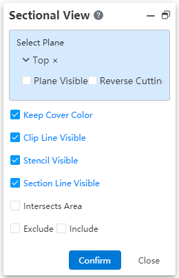
# Section view
- Display decorative thread lines correctly after cutting.
When cutting an entity with decorative thread lines, the decorative thread lines are displayed correctly, and the thread lines are displayed in the style that was cut.
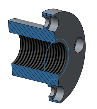
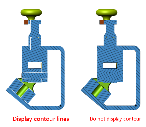
- In assembly and parts, the profile line can be displayed after cutting the model:
# New window opens the document
When creating a new Part, Assembly, Engineering Drawing, add the option "Open in new Window" in the bottom left corner of the dialog box shown below.
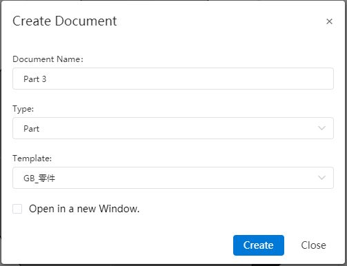
Unchecked (default) : After creating a document, open a new document in the current window, consistent with the original version.
Checked: After creating the document, create a new TAB to open the new document with the original TAB contents unchanged.
# Full Screen button
When a user logs into CC, add a "Full screen, Exit Full Screen" button in the top right corner of personal Settings.

When it is currently full screen, the "Exit Full Screen" button is displayed; Otherwise, the "Full screen" button is displayed.
Clicking the button will have the same effect as pressing "F11," even if the browser is full screen or exits full screen.
# Add/subtract button/scroll button
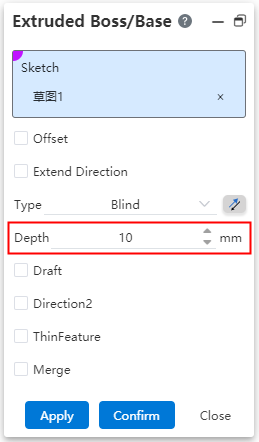
After the value input box, the value add or subtract button is displayed, and the value can be increased or decreased by scrolling the mouse wheel.
- After the value input box, the value add or subtract button is displayed, and the value can be increased or decreased by scrolling the mouse wheel.
The mouse rolls the wheel inside the value input box to increase/decrease the value. Scroll up to increase, and scroll down to decrease.
The law of value increase and decrease
Let the value increase or decrease variable be x;
Distance class value, x is 10;
Angle class value, x is 1;
Percentage value, x is 10%;
Quantity class value, x is 1;
Each time a button is clicked/the mouse wheel is rolled, the value increases or decreases by x.
Each time a button is clicked/the mouse wheel is rolled, the value increases or decreases by x.
Clicking the arrow or rolling the wheel will cause the value to exceed the limit, and the operation will have no effect.
For example: stretch the current depth of the boss is 5, click under the arrow or scroll down the mouse wheel back to make the value -5, then this operation is invalid;
Note that clicking on the arrow or scrolling up the mouse wheel can take effect normally;
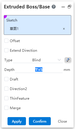
If the content of the input box is variable or equation, no button is displayed, and the value cannot be adjusted through the mouse wheel.
# Sketch Drawing
# 2D Sketch
# Dimension annotation
# Radius/diameter toggle
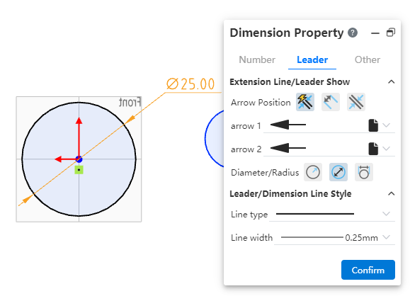
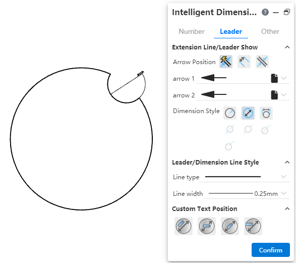
After the circle/arc is marked with smart dimensions, the "diameter/radius" can be switched.
Click on the marked radius/radius size to pop up the size property panel, switch to the "Lead" TAB, click on the diameter/radius icon to switch.
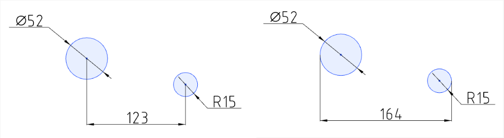
# Max/Min annotated
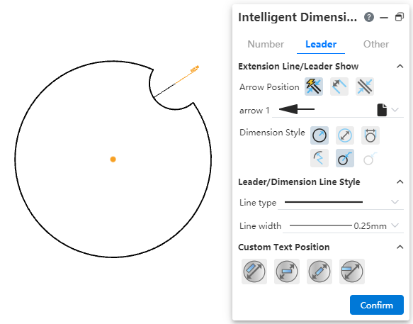
When there is a circle/arc element in the dimension annotation, the default annotation center distance; CrownCAD 2023 R3 dimension annotation adds the option of arc condition setting, which can switch the center distance to the maximum/minimum value.
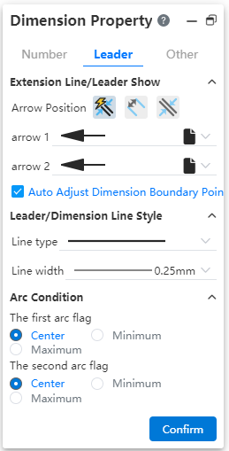
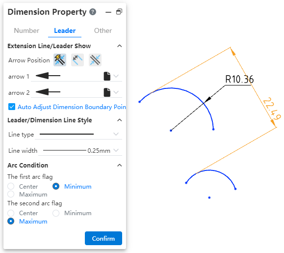
Click on the dimensioned dimension to pop up the dimensioned property panel, switch to the "Lead" TAB, you can set the dimensioned "center", "maximum" and "minimum" dimensions.
Example 1: Set the default labeled center size to the maximum size, as shown in the image below.
Note:
Show arc one and arc two when there are two circles/arcs;
When there is only one circle/arc, only arc 1 is displayed;
When marking, directly select the circle center does not appear the arc condition setting item, only select the circle edge line has its corresponding setting item;
The maximum and minimum point of the arc can appear on the imaginary circle where the arc is located, not limited to the arc, as shown in the following figure:
# Insert dwg
The dwg drawing can be directly inserted into the sketch, and the inserted dwg drawing has no difference with the sketch elements, and its elements can be deleted and dimensioned with the commands in the sketch.
Operation mode:
Click the Insert Dwg
 command to pop up the sketch plane selection pop-up window, and the selected plane is the Dwg drawing placement plane;
Enter the sketch drawing state, pop up the command dialog box:
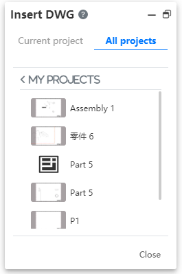
- Support to insert current project or other project dwg file.
Support to insert current project or other project dwg file.
The default origin position is inserted;
There are no constraints between the original elements, and the sketch can be completely defined by size constraints and geometric constraints.
# Change the sketch plane
Set a new datum or face for the sketch that has been created.
Right click on the finished sketch feature or sketch in the viewport and select "Edit Sketch Plane"
 to bring up the Replace Sketch Plane dialog box:
Plane: display the datum plane/plane of the current sketch, you can directly click on the face to be replaced in the viewport, the option box will automatically replace the newly selected datum plane/plane;
Copy: after checking, the new sketch is created on the new plane on the basis of retaining the old sketch, which is reflected as two sketches in the feature panel;
Original state


Uncheck "Copy" Check "Copy"
- Click OK to finish replacing the sketch plane.
- If there is a conversion boundary element in the sketch, re-project it after changing the sketch plane. If the projection does not conform to normal logic, the sketch line after switching the plane will remain consistent with the previous one, and the corresponding conversion boundary constraint will become an error constraint state, and the sketch can be restored to normal after deletion;
# Application - quickly determine the key
- The dialog box contains several consecutive pick boxes, which can be jumped to the next pick box by right-clicking the mouse.
When picking up the element you want to move in the first pick box, a prompt appears on the right side of the mouse in the viewport, as follows:
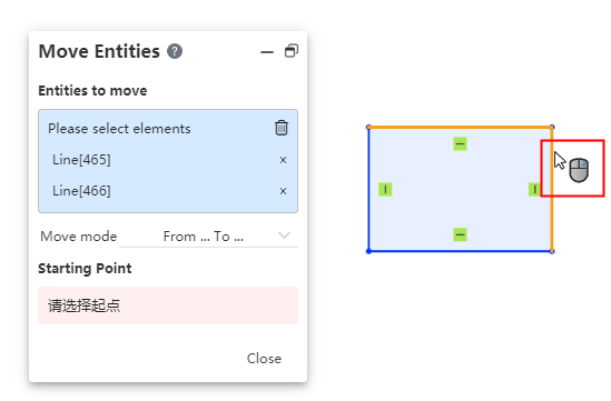
The user has the option to continue picking up primitives, and the identifier is always displayed:
When the identifier is displayed, click the right mouse button to jump to the next dialog box.
When the identifier is displayed, click the right mouse button to jump to the next dialog box.
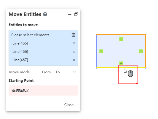
- After the last element pickup operation is performed in the viewport, it can be quickly determined by the right mouse button.
Upon completion of element picking, which can support the creation of the command, the right mouse button displays the confirmation identifier, as follows:

You can confirm the creation by clicking the right button, equivalent to the create or confirm button.
Note: The commands that show right click creation are: round, chamfer, array (circular, linear), zoom, rotate, offset, mirror, convert border.
# 3D Sketch
# Spline curves
Spline curves can be drawn in 3D sketch state.
Click the Spline Curve
 command in 3D Sketch to bring up the Spline Curve dialog box.
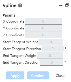
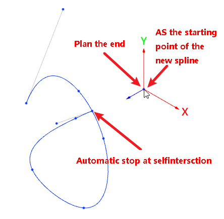
Click the pass point of the specified spline curve in the viewport in the same way that you would draw a polyline.
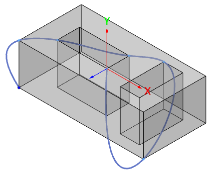
When drawing, you can switch the plane by tab key, and automatically judge the direction of the plane;
The passing point of the 3D grass pattern curve can not be on the same plane, and the generated curve can not be on a plane, but curved in space.
- Double-click the left button or click the Create button to finish drawing. The dialog box becomes the following style:
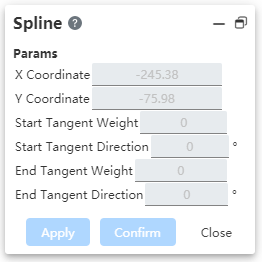
Double-click the left button or click the Create button to finish drawing. The dialog box becomes the following style:
# Parts and features
# Rotation feature enhancements
- Rotary boss/surface and rotary excision command, which automatically identifies the construction line as the axis of rotation;
If the sketch meets the following conditions, the reference line in the sketch is automatically picked up as the axis of rotation.
The sketch has one or more contours that can be rotated, and in addition to the contours, there is only one guide line;
The reference line is a straight line;
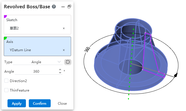
Other rotation axes can be re-picked regardless of whether the automatically picked rotation axis can generate a rotation feature.
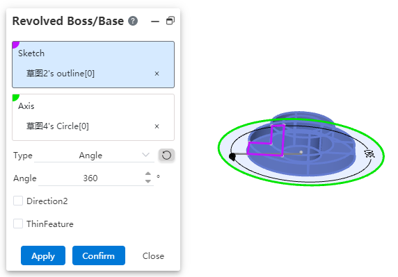
- Support the selection of more type elements as the rotation feature rotation axis;
Circular edge line: perpendicular to the plane of the circle, the straight line over the center of the circle as the rotation axis;
Including sketch, surface/solid edges;
Full circle or arc;
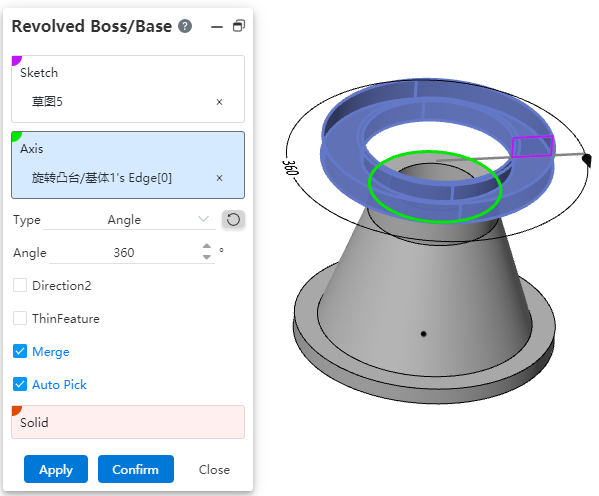
Cylinder: The axis of the cylinder acts as the axis of rotation;
Cylinder: The axis of the cylinder acts as the axis of rotation
Complete and incomplete cylindrical surface can be;
Two points: A straight line formed by two points acts as the axis of rotation;
- Support reference point, sketch line endpoint/drawing point, solid surface edge line vertex/midpoint, space curve endpoint;
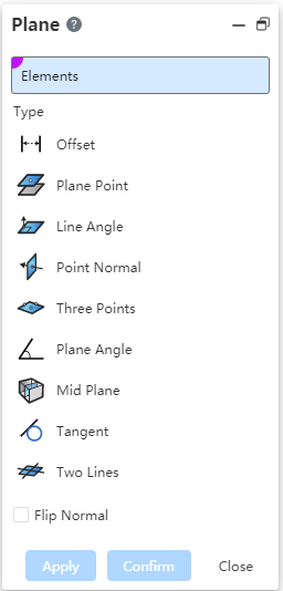
# Datum - midpoint
Generate a two-plane midplane between the two datums/planes chosen.
| Pick the relative position relationship of the plane | Diagram |
|---|---|
| Parallel (Choose the left and right sides of the model) |  |
| Coincident (Pick the top of both models, located on the same plane) |  |
| Intersecting (Pick the top and bottom of the model) |  |
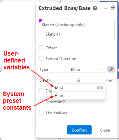
# Variable management
Support constant - PI selection input, to ensure the accuracy of calculation.
When you enter "P" or "PI" (case insensitive) in the input box that supports equations, the "pi" option is displayed. Select this item to fill the function pi into the cursor of the input box.
The user can create a variable named pi that does not conflict with the system default variable value pi. In the input box, single quotes are displayed on both sides of the variable pi, while the value pi has no single quotes on both sides, as shown below:
# Quality attribute - Add model matrix information
When evaluating product quality attributes, model matrix information is added to the results and a coordinate system representing the model's inertial principal axis and mass center is displayed in the viewport.
- The information display of the principal axis of inertia, the principal moment of inertia and the tensor of inertia is added;
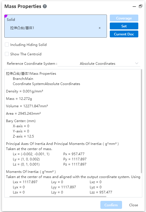
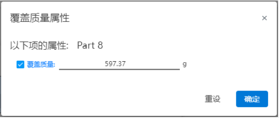
- Through the overlay command, the numerical value can be input to overlay the calculated mass;
Click reset to restore the filled value to the calculated value;
You can choose the tensor notation convention in the Settings, default to "positive tensor notation", in the positive and negative two ways to choose one;

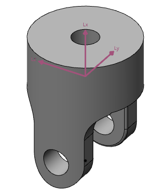
When the mass properties dialog box is opened and the result is calculated, a pink coordinate system is displayed in the viewport, representing the inertia axis and the center of mass of the model. When the dialog box is closed, the coordinate system disappears.
# Curves
# Decorate threaded lines
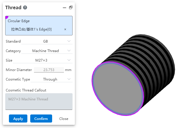
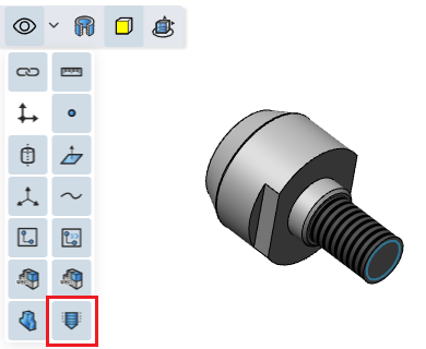
Add decorative thread lines for cylindrical/round table surfaces without creating real threads, adding a realistic look to the model without adding complexity to creating real threads.
Click the decorative thread line

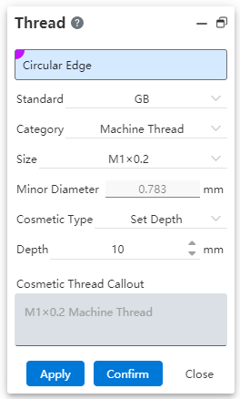
Select the round edge, default standard is GB, generate the appropriate thread path value according to the selected circular edge diameter value, the way defaults to the given depth, and then generate the decorative thread.
The selected edging line must select a solid circular edging line;
Support the selection of solid edge lines such as cylinder, round table and hole features for feature creation;
Support the selection of solid edge lines such as cylinder, round table and hole features for feature creation;
Imported model, support to pick up the cylinder/round table body, hole characteristics round edge line to add decorative thread line; (If the imported cylinder is divided into two faces, do not support the addition of decorative thread line)
When the standard is GB, the type and specification selection bar will pop up, the default is ordinary thread, and the specification gives the appropriate range according to the diameter value of the picked round edge line, and calculates the thread path value to generate the decorative thread line;
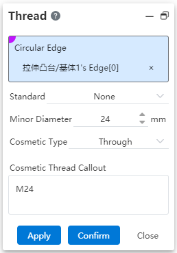
When the standard is no, manually fill in the thread path value to generate the decorative thread line.
- The decorative thread line is marked:
The command box automatically generates the annotation according to the selected specification, and the annotation can be manually changed to be consistent with the annotation value when the thread is marked in the engineering drawing.
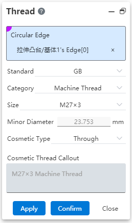
In the GB state, the annotation displays the specification + type by default. If the specification type changes, the annotation changes synchronously;
Support to modify the annotation, after modification will not reverse adjust the type and specification.
- Decorative thread implicit:
Control the visibility of decorative thread line in the view toolbar "Visibility Tool" (control of decorative thread line and map at the same time).
# Weldment design
# Structural member grouping enhancement
Picking parallel paths or connected paths is supported when selecting path groups.
When picking up parallel paths, the paths in the same group are required to be parallel to each other;
When picking up connected paths, the paths in the same group are required to be connected in turn;
Parallel and connected paths cannot exist in a group at the same time;
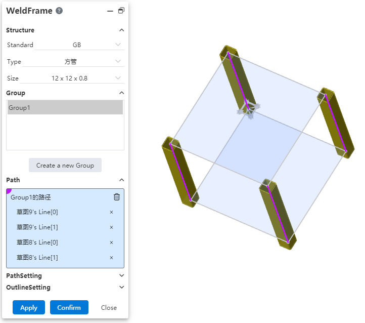
# Customize the structure component outline
Users can draw their own sketches and save them as weldment structure Outlines for use when generating weldment structure members.
- Custom contours
1)Users can draw 2D sketches on any plane and save them as structure Outlines.
2)Sketch requirements:
- The sketch must contain a closed sketch area composed of non-reference lines, but there can be no more than one sketch area;
| Sketch style | Single closed area | Single closed area with internal outline | Multiple closed area | Unclosed area |
|---|---|---|---|---|
| Legend |  |  |  |  |
| Supported | Yes | Yes | No | No |
The sketch may contain auxiliary guides, drawing points;
The origin of the sketch will default as the penetration point in the component that coincides with the path;
The sketch size can be defined by variables or constants.
3) Contour material function
Set the document material for the sketched part document. After the sketch is saved as the weldment structure outline, the document material is used as the profile material;
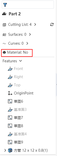
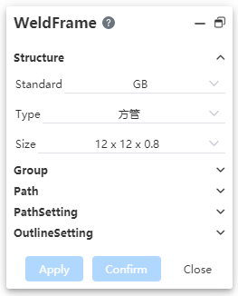
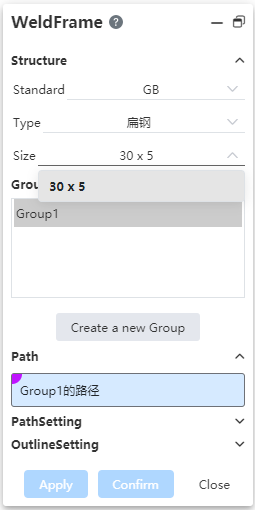
When using the custom outline in the structural component, select the outline with the outline material can check the "use the outline material" option, and set the outline material as the material of the corresponding component.
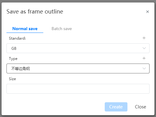
- Save the outline
1)Click the arrow to the right of the Save button and select "Save as Outline" to bring up the "Save as Outline" dialog box to save the structure outline.

Before saving, the sketch to be saved should be selected in the feature panel;
If there is only one sketch in the document, there is no need to select, and the system automatically saves the only sketch;
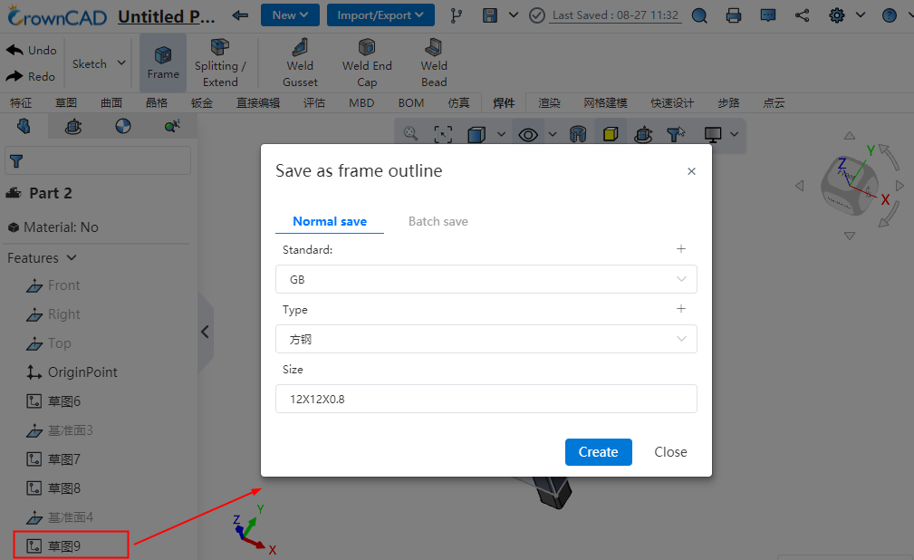
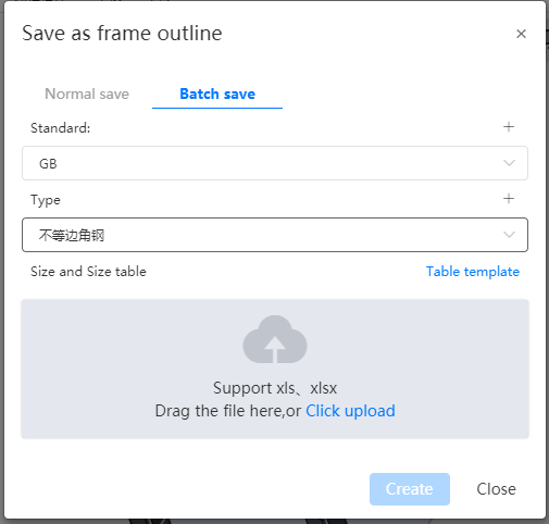
2)Support ordinary saving and batch saving two saving methods
- Ordinary save: save the outline of a single size, the size of the outline sketch is the size of the sketch in the current part;
- Batch save: upload a table that conforms to the rules and generate multiple Outlines of different sizes in batches. The size of each outline is controlled by the variables in the table and the corresponding size variable in the sketch;
- Save the table rules in batches:
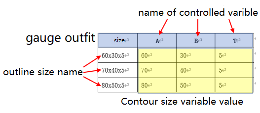
①The first line of the table, starting from the second row each row represents a specification;
②The first action table, starting from the second row each row represents a specification;
③The head of the first list is "size", and the content is the "size" name of each outline. Starting from the second column, the name of the table head is consistent with the name of the variable controlled by the column data, and the content is the value of the corresponding variable in the outline of each size. To control several variables, add several columns of data. Special characters that are not supported as names are not allowed in this column;
④Blank cells are not allowed in the table head, contour size name, variable name, variable value of each contour size;
⑤The variable name must correspond to the name of the variable created in the sketch in order to take effect correctly. The variables that exist in the table but are not in the sketch are ignored and not used. The variables that exist in the sketch but are not in the table are taken as the values of the variables in the sketch.
3)Save custom outline examples:
Create A new blank part document and set variables A=60,B=30,T=5

Draw the following sketch on the front view datum, annotated using the variables in step 1

Store separately: Select standard GB, type L-shaped steel, size 60×30×5. After saving: Add 1 outline to standard GB, type L-shaped steel, size 60 x 30 x 5, size as in the sketch.

Note: The standard and type can be selected as existing, or you can click the "+" sign in the upper right corner to create it. The created data will be automatically recorded in the library and can be directly called later.
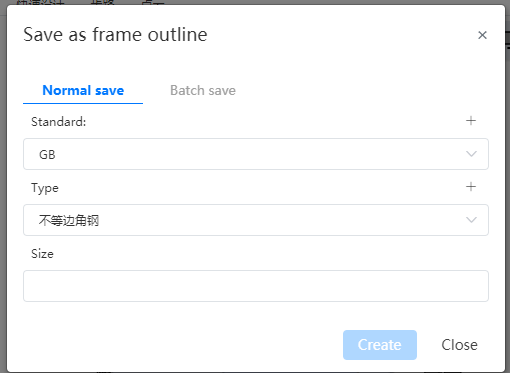


- Batch saving: Select standard GB, type L-shaped steel, upload the table as shown below.
| Size | A | B | T |
|---|---|---|---|
| 60×30×5 | 60 | 30 | 5 |
| 70×40×5 | 70 | 40 | 5 |
| 80×50×5 | 80 | 50 | 5 |
- After saving: Standard [GB], type [L-shaped steel] there are 3 Outlines, the size is "60×30×5,70×40×5,80×50×5", the specific size of each sketch is controlled by the value of each size corresponding to A, B and T in the table.
- Manage the outline
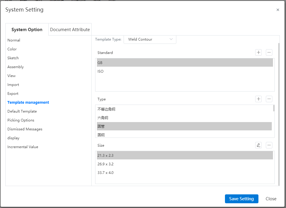
1)Select "Weldment Profile" in System Settings - System Options - Template management to manage.
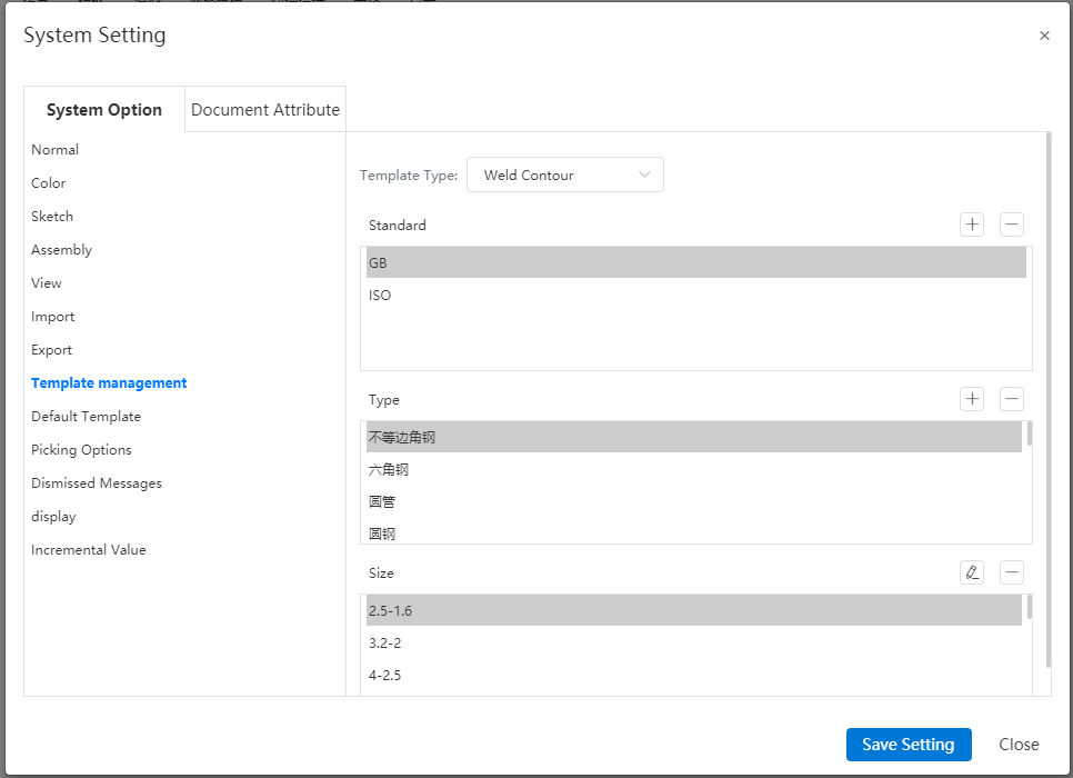
2)Select the outline to be edited and click  the edit command to enter the sketch editing state as shown in the following figure, you can edit the sketch corresponding to the size.
Note: Editing the outline needs to be carried out in the project management state. When the system is in any open document state, editing the outline will prompt "Please exit the current document first".
3)Click Save after modification to save the current modification, you can not exit the sketch by exit sketch button.
4)Click the Back button to exit the workspace and return to the home page. If the changes are not saved before returning, a confirmation dialog box "Save structure outline" will pop up:

5)Click OK to save and return to the home page, click Cancel to return directly to the home page without saving the changes.
# Weldment cut list Enhancement
You can customize the created cut list, add or subtract columns, and modify column properties.
# Add or subtract columns
When adding a column, you can choose to add a column to the left or right of the selected column; When deleting a column, multiple selection deletion is supported;
Mouse to cut list;
Right click the "ABC..." representing the column that appears on the cut list. ", click the column number and select the whole column;
Right click the "ABC..." representing the column that appears on the cut list. ", click the column number and select the whole column;
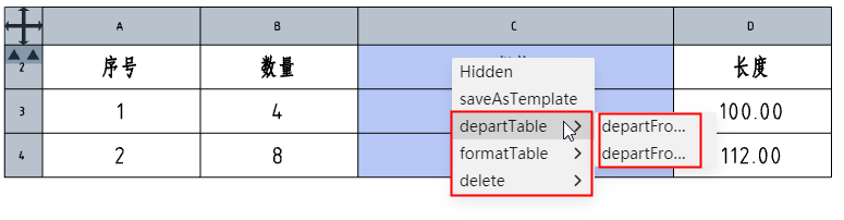
Press ctrl key and click the column number to select multiple columns for deletion at the same time;
# Modify column properties
Supports modifying the properties of a column (the properties are what the column displays).
Mouse over the cut list;
Left-click on the "ABC..." representing the column that appears on the cut list. ", the "Table" dialog box appears:

Modify the properties, titles, etc. to be displayed in the dialog box;
Supported column properties:
Item number: Serial number of the cutting list item, corresponding to the part serial number;
Quantity: the number of the same cutting list item (entity);
Cutting list item name: the name of the cutting list item, such as "square pipe 14 x 14 x 1";
Cutting list item name: the name of the cutting list item, such as "square pipe 14 x 14 x 1";
Cut list item properties: Select the weldment cut list properties from the list, including "Angle 1, Angle 2, length, material, quantity..." ;
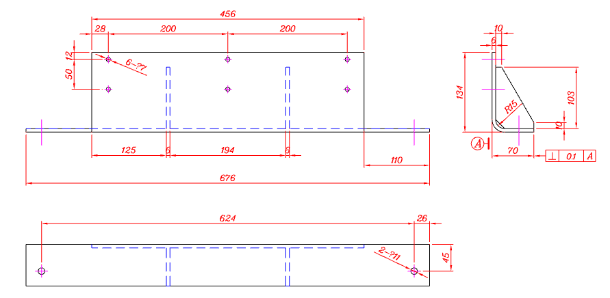
For common entities such as corner brace boards, support reading their properties.
# Assembly design
# The first part of the assembly is automatically positioned and fixed
When there are no parts in the assembly, open the [insert parts] command, the default check is "insert at the origin", and the check is automatically unchecked after the first part is inserted; The first part inserted automatically adds a fixed constraint.
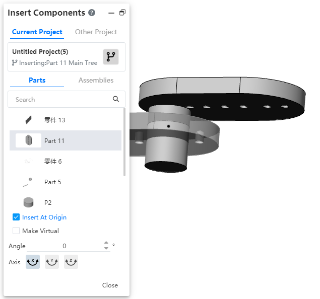
# Optimize insert parts operation
Insert parts dialog box, cancel the preview button, select the insert object and move the mouse to the viewport to automatically appear preview, move to the desired position and click the left button to insert parts.

When the inserted part is a blank document, it will change into a blank document when the mouse moves
 s to the viewport for preview, and will return to a blank document after clicking and placing
 .
.When inserting standard parts, continuous insertion is supported.
# Drawing
# Views
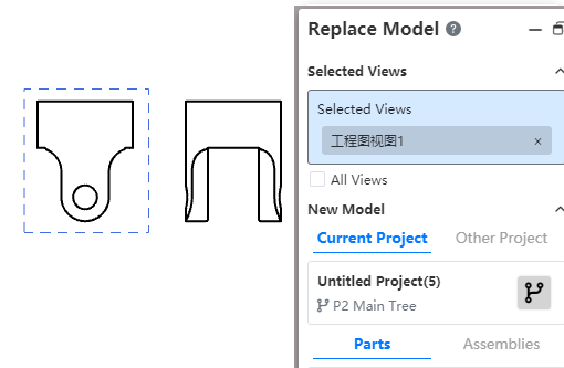
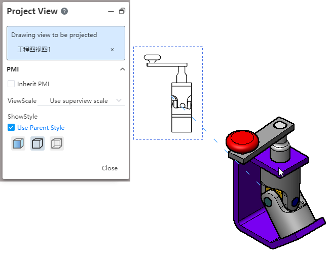
# Replacement model
Select the view or view feature to specify the reference model that the model replaces the current view.
Right-click the view in the project drawing and select the "Replace Model" command to start the Replace view feature.

Click Select View in the Viewport or View panel.
- Select the view rule:
- Supports picking in viewport or view panel.
- Can only pick up the first level of the model view, can not select the subview.
- Select the view rule:
Click the "Browse" button to select the target part or assembly;
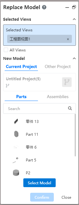
Click the "Select model" button, the selected parts are displayed in the dialog box, and judge the view type in "Selected view", according to different types, display the corresponding icon in front of the view:
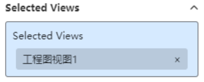
Normal view Not replace - Normal: A view that can be replaced normally, showing only the view name and no icon.
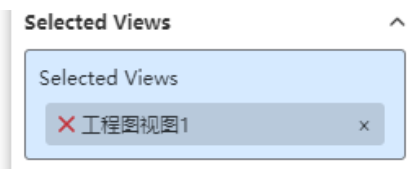
- Not replaced: The model inside the view is the same as the selected target model. A red X is displayed before the view name, this type of view does not perform a replacement operation.
Click OK to complete the replacement.

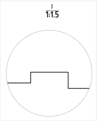
- The "normal" view is replaced normally, in the same direction as the original view.
- The Do Not Replace view does not replace.
- The subview model of the replaced model's view changes.
- After the model is replaced, the annotations in the original view are deleted.
# Local view optimization
The name location of the local view is generated above the local view by default. You can drag and drop the name location.
# Customize the scale of the view
The scale option in the Drawing View allows you to select "Use Custom scale" to manually enter the scale.
# Annotations
# UI Panel optimization
Smart Size dialog modifies the styles shown below.
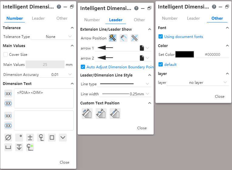
Associated characters contained in Angle brackets can be entered into the text input box.
- For example, MOD-DIAM represents the diameter symbol and DIM represents the main size.
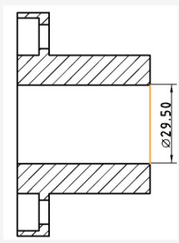
# Enhance smart dimensioning
Automatically add the diameter symbol before the main value of the size when sizing the silhouette outline of the cylinder through smart dimensioning.
When smart dimensioning a circle/arc, the "diameter/radius" can be switched.
# Add chamfer dimensions
Added chamfer dimensioning function, support for labeling chamfer and optional chamfer style.
Click the "chamfer size"
 command in the smart size drop-down menu to pop up a dialog box:
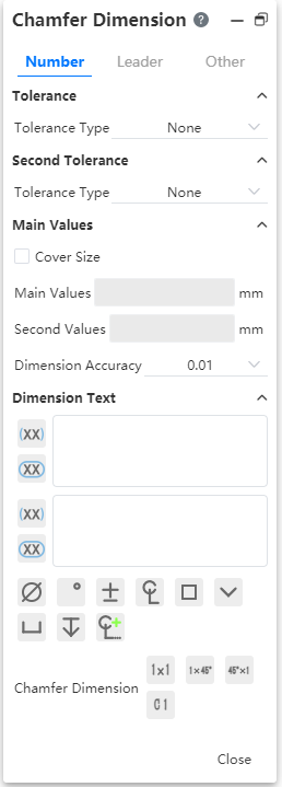
After starting the chamfer size command, pick up the chamfer bevel and reference edge in turn, and move the mouse to show the chamfer annotation preview;
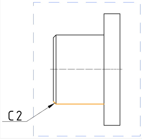
- Requirements for beveled edge and reference edge:
- The order in which the edges are selected depends on the result of the annotation, the first is the hypotenuse and the second is the reference edge.
- Support the model lines or edges of the sketch for the view.
- Must be straight lines.
- The two sides must be connected.
- Both sides must be edges of the same entity/surface, or belong to the same sketch.
- Requirements for beveled edge and reference edge:
Select the chamfer size display style:

Switch to the "Lead" TAB and select the chamfer size limit, Lead size line display style, and custom text position:

Click the Close button or press the Esc key to finish labeling the chamfer size.

# Hole labeling
The hole annotation dialog box is optimized to fit the new smart size dialog box.
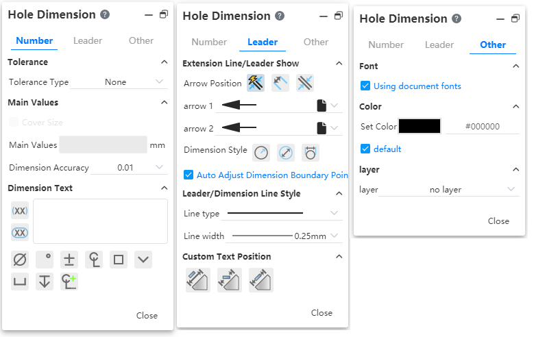
Hole annotation supports diameter radius switching. Set this at the Hole labeling dialog box "Lead - Size Line/Lead Display - Diameter/Radius".
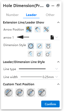
Hole labeling supports selecting arrow position. Set this at the hole label "Lead - Size Line/Lead Display - arrow position".
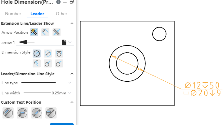
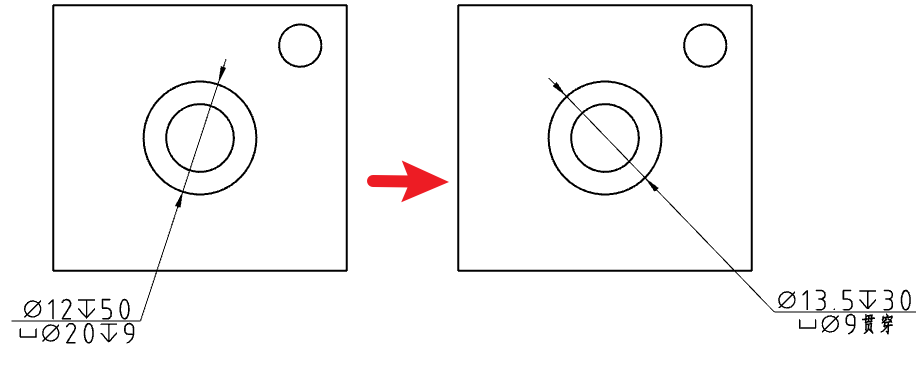
The content of the text box of "Marking Size text" in the hole marking dialog box corresponds to the text information of the hole marking, and the content is composed of "special symbol, associated size, text", which supports custom size.
# Form and position tolerance
Change the lead position to fit multiple rows so that the lead is in the vertical middle.
No matter how many rows the tolerance frame has, the side of the lead connecting the frame always remains in the center of the vertical line of the frame.
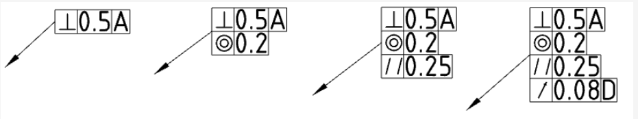
When the frame adds or deletes lines, keep the position of the upper left vertex of the frame unchanged, and the position of the point connecting the frame with the lead line changes with the number of lines in the frame.
# Drawing annotation library - annotation library
It is used to store the commonly used annotation symbols and texts in engineering drawings, and supports input, call, delete, find, etc.
Click the knowledge base list on the right side of the graphic viewport to view all the contents of the personal knowledge base. The top half displays the default detailed list (the default is only the annotation library). After double-clicking on the name of the list, all annotations in this list will be displayed in the "Details panel".

The meaning of each icon
| Icon | Name | Description |
|---|---|---|
 | Step back | To exit the currently selected library and close the display in the Details panel |
 | Forward | To open the selected library, the details panel displays the current library information |
 | Add to library | Add comments to library, support comments, surface roughness, form and position tolerances |
 | New folder | After selecting the library, create a new folder in the lower part of the library; Do not select the library, create a folder in the top layer, and maintain a parallel relationship with the original folder |
 | Search | For the searchable folder name, file name |
 | Return to the previous level | Return to the parent folder of the current folder, and the details panel is updated synchronously |
# Annotation library input
Method 1
- Select the desired symbol or comment in the project drawing viewport and right-click to bring up the right-click menu.
- Select "Add to Knowledge Base" from the pop-up right click menu, and the "Add to Knowledge Base" dialog box will be displayed.
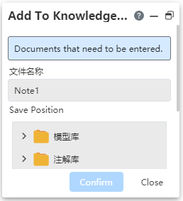
Items to add: Fill in the elements to save to the library, support comments, surface roughness, form and position tolerances.
In the file name text box, fill in the file name, the required field, the default name is "comment 1".
Set the storage location, the knowledge base folder structure tree to select the storage folder.
Method 2
- Click the "Add to Library" icon in the Knowledge base to bring up the Add to Library dialog box.
- Select the element you want to add in the Drawing View window, and the item bar you want to add displays the name of the selected element.
- Fill in the name of the file in the File Name text box.
- Select the storage folder in the storage location.
- Click the "Add to Library" icon in the Knowledge base to bring up the Add to Library dialog box
# Annotation library call
- Click Knowledge base in the right side of the software thumbnail, the knowledge base interface pops up.
- Double-click the target folder, "Details panel" display all the annotation information saved under the current folder.
- Drag and drop the content to be added to the viewport. Attach the content to the mouse icon and move with the mouse.
Click on the appropriate position of the project drawing to realize the annotation content placement, then pop up the Insert annotation dialog box.

- After finishing the placement, the preview effect of the selected comment will appear at the mouse icon. Click in the blank position of the project drawing to continuously place the selected comment.
- In the dialog box, click Close to end the annotation insertion, and press Esc key to end the annotation insertion.
- Double-click the placed comment and enter the editing state according to the comment type. If the comment is shape and position tolerance, open the editing dialog box of behavior tolerance.
- When a view element that supports addition is prepicked during placement, the element is highlighted.
- Deleting annotations from the library does not affect annotations that have been applied in the current view or other documents.
# Tables
# BOM Table enhancements
# Merge/split cells
Enhance the editing of the form of the material list, support the merging and unmerging of cells in the table, vertical splitting, deleting columns and other operations.
Merge cells: Select multiple cells in the table to merge.
- Hold down the left key and drag in the table, or hold down Shift and click on two different cells to select a region of cells that can be merged.
- Scattered multi-selected cells cannot be merged by holding down Ctrl.
- The selected cells cannot be merged if they contain cells that have already been merged.
Unmerge cells: Cells that have been merged can unmerge cells, content handling rules:
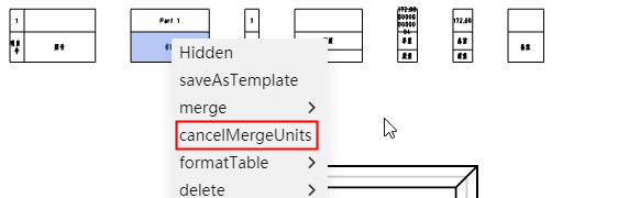
- Let the contents of cell A be filled into the merged cell when merging cells.
- Then when the merged cells are unmerged, the contents of the merged cells are filled into cell A, and the contents of the other cells before the merger are restored.
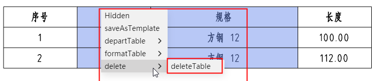
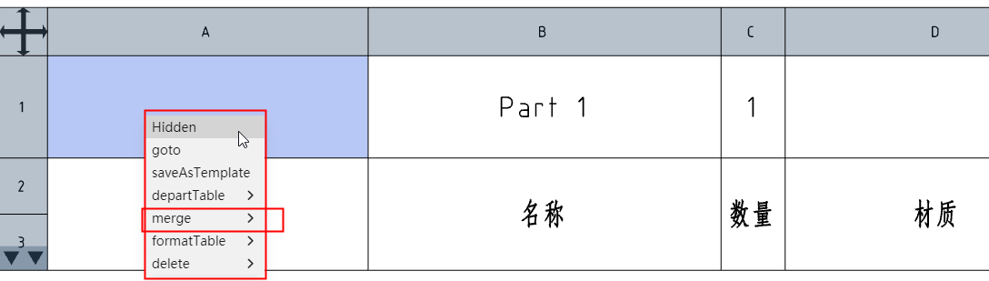
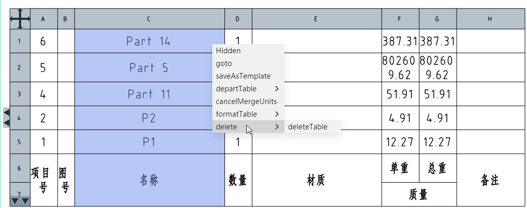
Delete column: Click the column number, select the whole column, right-click menu "Delete" appears in the "Delete column" selection.
How to merge cells and delete columns:
Unmerge the cells, then delete the rows, and then re-merge the remaining cells.
The process of unmerging and re-merging is not visible, only the final result is displayed.
# Enter the equation
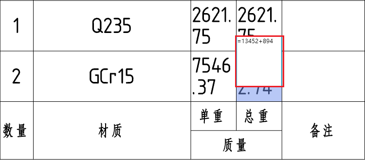
Table cells such as material detail sheets support entering equations.
Enter "=x+x" as well as any other supported formulas and insert the formula result into the cell by clicking Enter or clicking the blank space to end the input.
Formula requirements for computable results
The formula begins with an equals sign.
Only operators and numbers are supported in formulas.
If you cannot get the result of the calculation (for example, if you enter =1/0 or if the formula contains uncomputable text such as letters), keep the formula you entered.
When you edit cells again, the content shows a formula such as "=x+x" instead of the result, and you can modify it.
# Toggle column properties
Double-click the column number, the "Table" property box will pop up, and the property value of the current column can be switched:

Supported column properties:
Custom properties: Select properties from the custom properties template, figure number, etc.
- When selecting the weight, two sub-options of "single piece, total" are displayed, and single piece is selected by default.
Item number: The item number corresponding to the part serial number function.
Part Number: The name of the part, which is the name of the document.
Attributes of standard parts: Specifications of standard parts, optional "part name, specification, annotation".
The title of the table header is the same as the selected property name by default, and can be modified by double-clicking the cell in the table.
# Cooperate
# Team
- Enhance the team creation and member management functions, change the existing organizational structure, change to the creator, manager and member three roles, different roles have different permissions.
| Role | Rules |
|---|---|
| Creator | Team The creator is the default creator role, has the highest permissions, a team has only one creator, and is not transferable, support to modify team information, support to add team members, support to change the permissions of other members, support to delete members, support to delete the team.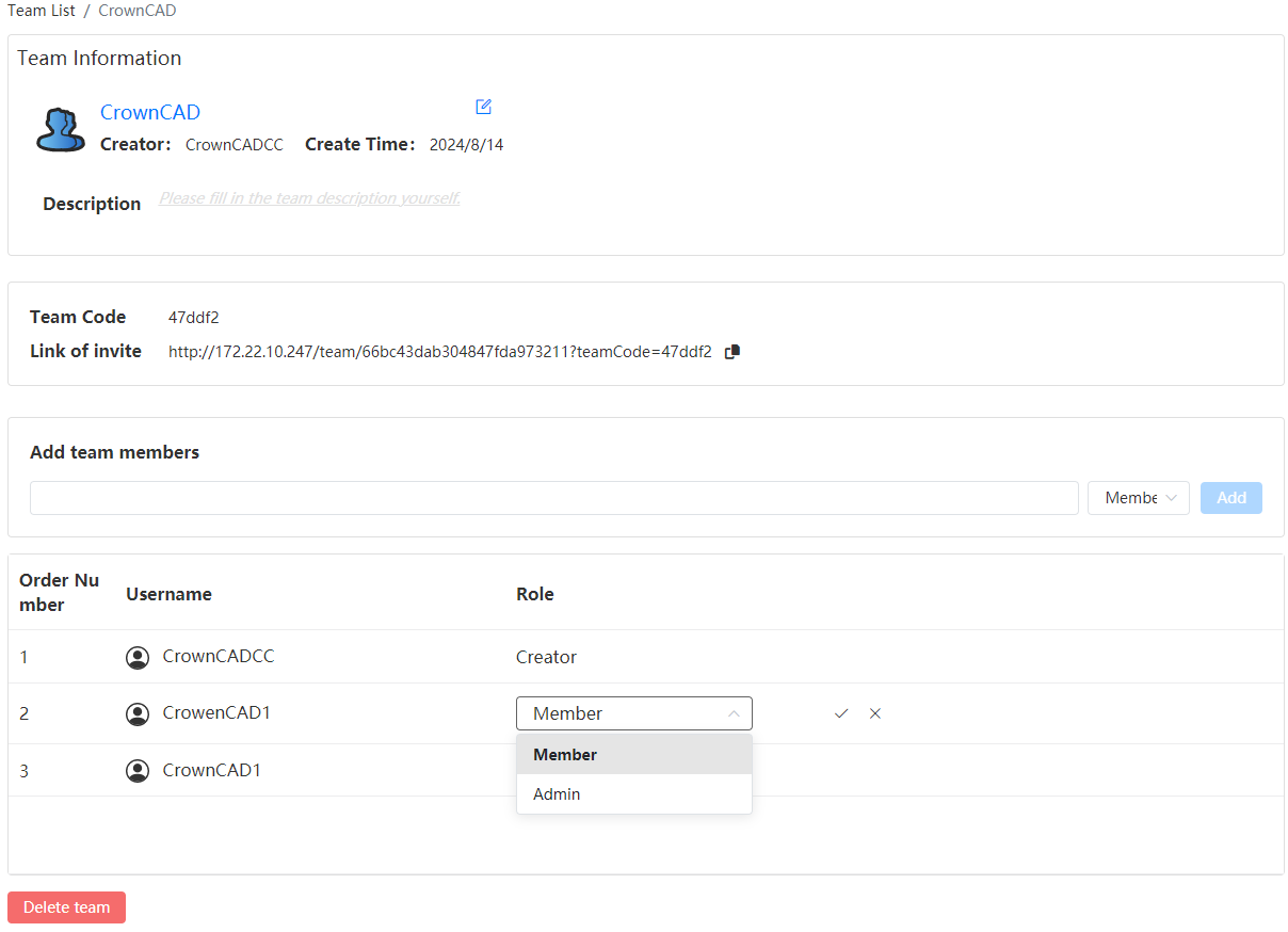 |
| Management | Management has second permissions, a team can have multiple management, support to modify team information, support to add team members, support to delete members.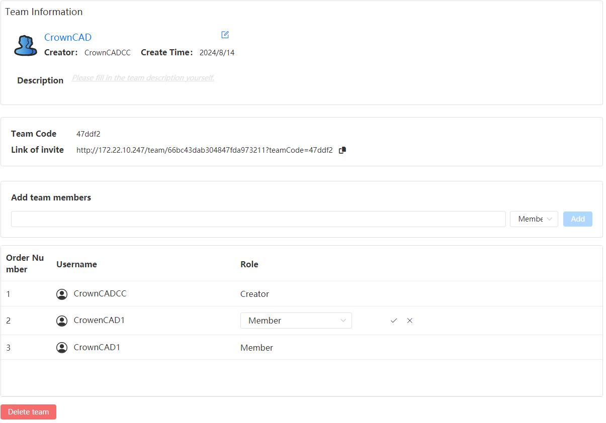 |
| Member | Member is the lowest permission, you can view the creator and team description, do not support to change the team description, support to leave the team.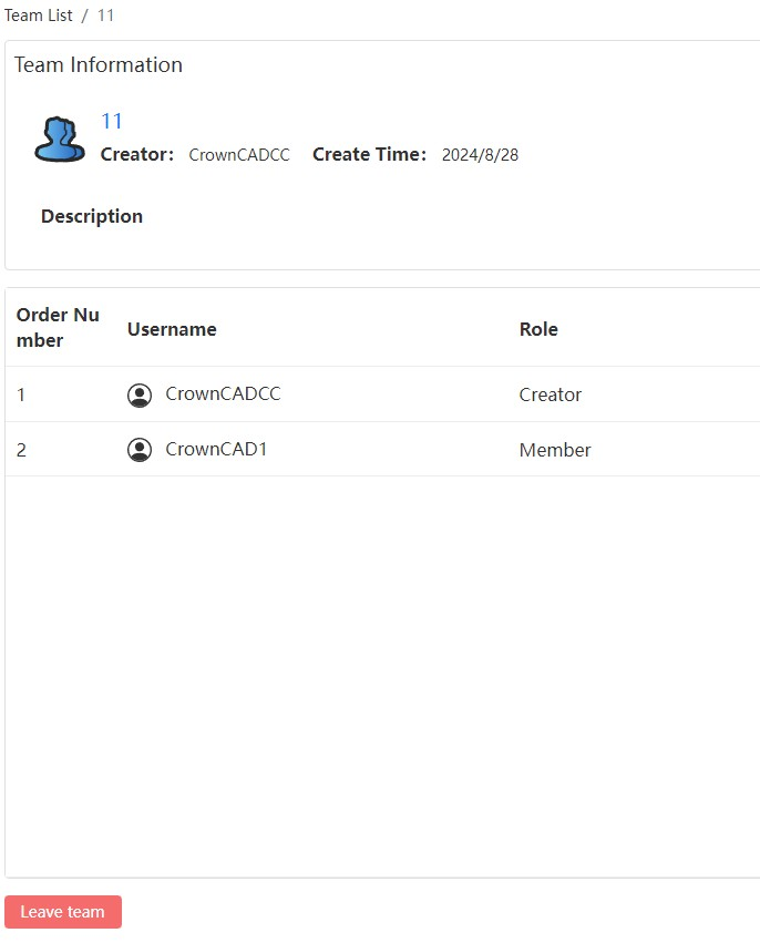 |
- Add a team code to the team management page for quick invitations to members.
# Activity
CrownCAD 2023 R3 enhances the overall activity module, optimizes activity project management, activity review and other functions, adds activity management, adds audit mechanism for public activities, and avoids the display of a large number of invalid activities.
# Activity Management
- Add review mechanism: in the initial state of the module, the public list is not displayed, and the created activities are displayed in the "My activities" list. Only after the application is made public and approved, the public list and public activities will be displayed;
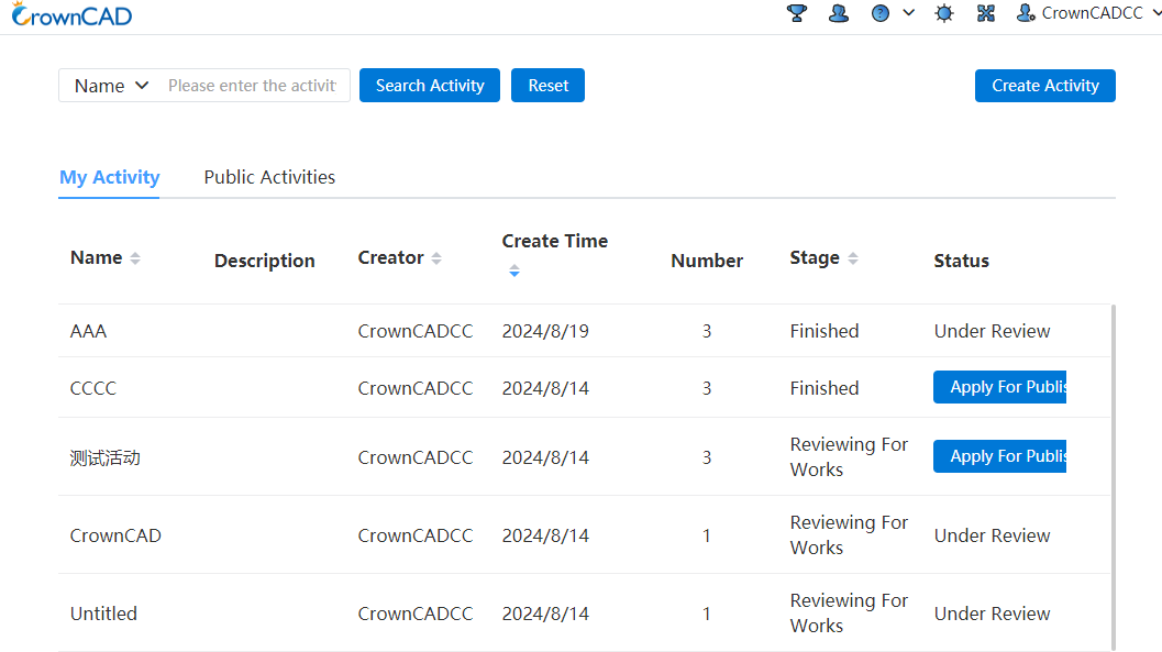
- Add the status bar display: "My activities" list adds the "status" bar for the display of activity status, including the application for public button, review, has been published three states;
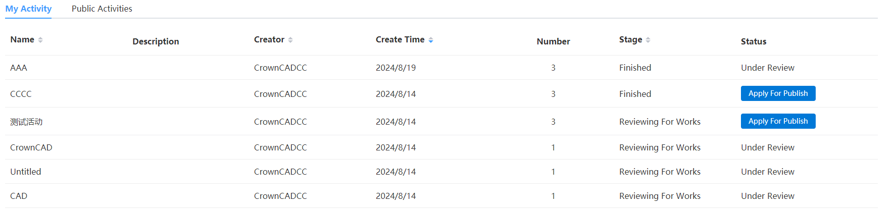
Note: After the activity application is made public, the status bar is displayed as "under review", and after the review is passed, the status is changed to "public"; If the review is not passed, the status will be changed to the application public button;
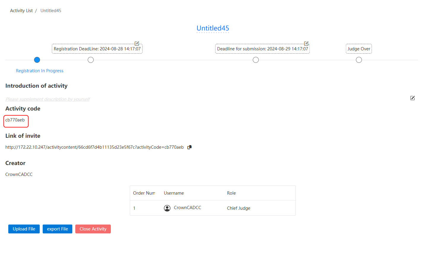
- Activity list Click on an activity to open the activity details page. If you have joined the activity, you can see the activity code. If you have not joined the activity, the activity code will not be displayed on the details page.
# Create/Join an activity
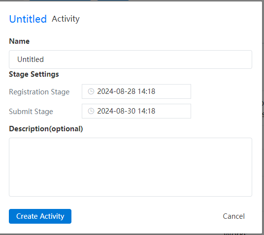
Optimize the time control of creating activities, add the function of joining activities restriction, role authority management, personnel list display, and publicity results.
- The registration phase and the submission phase are allowed to be on the same day, but the submission phase deadline must be after the registration phase deadline.
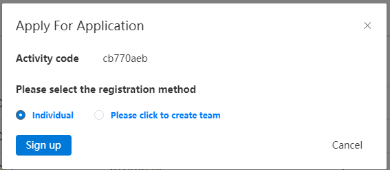
- Control the permission of joining activities, and add restrictions on entering activity codes in the "Registration" interface to prevent anyone from joining activities, which may lead to the disclosure of activity information.
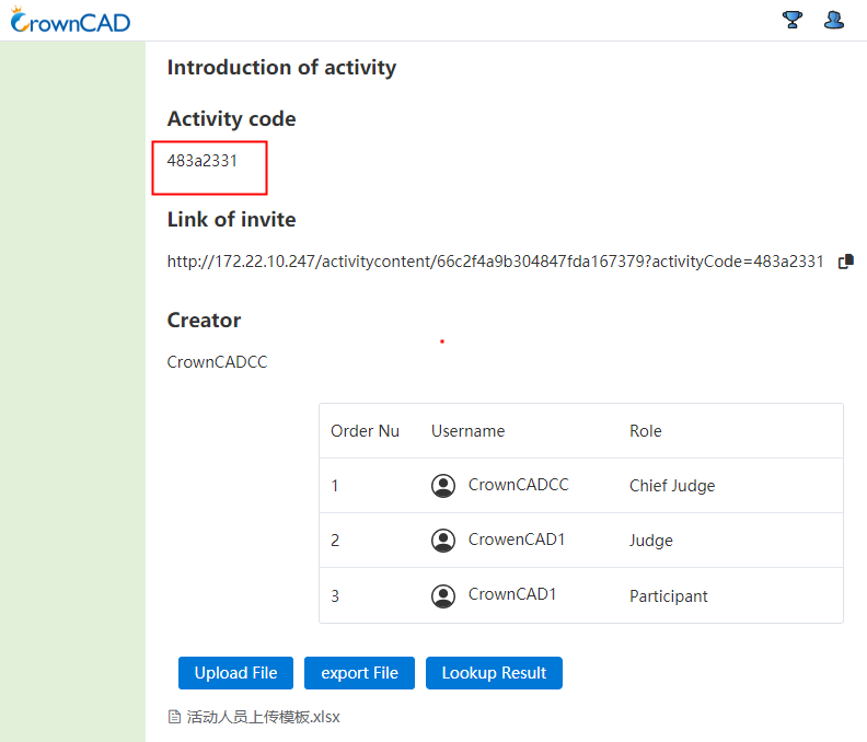
- In terms of activity authority management, the role of the main judge is added. The creator of the activity is the main judge by default, and other roles are controlled by the main judge. Different roles have different permissions.
| Role | Rules |
|---|---|
| Main judge | The creator of the main judge activity, has the highest authority, an activity only one main judge, and cannot be transferred, you can view the name of the activity personnel (name shows the full name), support to change the rights of other roles, support to delete the role, support to publish the results, support to end the activity.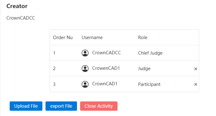 |
| Multiple judges | The judge has the second authority, an activity can have multiple judges, set by the main judge, the judge can view the list of activity personnel (main judge/judge/all contestants show the full name), support to delete roles, support to view results, support to leave the activity. |
| Participants | Participants have the lowest permission, an activity can have more than one participant, support to view the list of active personnel (main judge/judge/I show full name, other contestants show initial +***), support to view the results, support to leave the activity. |
- After the event review, support to upload and view the results of the competition, the main judge click on the announcement results, open the upload dialog box, select the corresponding file to upload; Judges/participants, click to view the results, download the corresponding file.

# Activity Project management
In the active project list, the name of the project owner is displayed according to different roles.
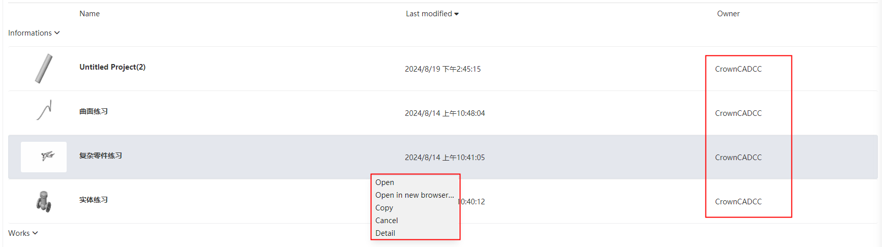
| Type | Name | Rules |
|---|---|---|
| Right-click menu | Copy | 1) All personnel in the activity can copy the project shared by the main judge/judge, and the copied project will be displayed in My project (the subsequent folder copy should be supported, the current product does not support folder copy, and the subsequent addition should be updated simultaneously); 2) The main judge/judge of the project shared by the participant does not have permission to copy. |
| List | owner | 1) The lead judge can view the name of the project owner shared by any character; 2) the judges can see the project owner names shared by the main judges/judges, and all the contestant owner names are displayed as ***; 3) Participants can see the project owner shared by the main judge/judge, and participants can only see their own works, can see their own owner name. (Synchronously adjust folders, project pages, document pages, and details) |
# Activity Review
- Read only mode support model cutting view, including parts, assembly module.
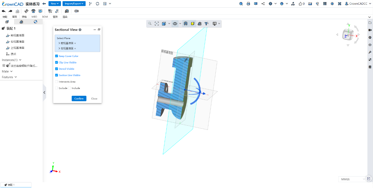
- Assembly read-only mode, in the feature tree right-click list to add "hidden", "all hidden", "all show", for the judge review to view the internal structure, refresh after the restoration.

← 2024 R1 Sign Up/In →