Welcome to the CrownCAD 2024 R1
CrownCAD 2024 R1, both in terms of functionality and ease of use has been greatly enhanced, these requirements are based on the most real user feedback. These features help you accelerate and improve your product development process.
Key enhancements:
| Highlights Features | Bridging surfaces |
| Bridging curves | |
| Lattice modeling | |
| Structural simulation | |
| Batch export | |
| Library application and management | |
| Applications | Enrich the system Settings, add Chinese and English switching, mouse reverse, import precision and other Settings |
| Optimize the rotation operation of the viewport, support custom rotation point/rotation axis | |
| Supports custom dialog box size and unified application buttons | |
| Support quick pick point, unified box selection | |
| Perfect right-click menu | |
| Support assembly environment to set appearance and add appearance library | |
| Sketches | Provides a default equation curve library and supports custom equations |
| Add ellipse/ellipse arc | |
| Add symmetrical dimension, 0 dimension | |
| Optimized offset, can be applied directly out of sketch elements | |
| Added automatic scaling of sketches for the first time | |
| Add 3D sketch symmetry constraints and optimize drawing interactions | |
| Parts and Features | Support for multi-profile drawing |
| Optimize hole point interaction | |
| Increase the center of mass | |
| Save entity | |
| Assembly | Optimize assembly images to generate reverse documents |
| Optimize replacement parts function | |
| Optimize the application of TopDown external references | |
| Add advanced fit - distance/Angle limiting mate | |
| Added mechanical fit - Notch mate | |
| Add large fit mode | |
| Added Show Parts feature to quickly show hidden parts | |
| Drawing | Add custom section lines |
| Add a disconnected section view | |
| Added cropping view | |
| Add sheet metal slab engineering drawings | |
| Add in-view sketching | |
| Support for generating explosive views | |
| Enhanced centerline functionality | |
| Add revision table, revision cloud, and revision symbol | |
| Support 1:1 ratio output engineering drawing | |
| Optimize title bar editing | |
| Increase custom drawing scale | |
| Added mouse gestures | |
| Add view scatter with alignment | |
| Variable management | Increase equation library |
| Evaluation | Enhancing quality attributes |
| Enhanced interference check | |
| Sheet metal | Increased closing Angle |
| Weldment | List of reinforced weldment cuts |
| BOM | Added custom material library |
| Enhanced custom property Settings | |
| Optimize node branch properties | |
| Data conversion | Support the import of RVT, 3DXML, SAT, Inventor format files |
| Support to read hidden body/surface/curve in assembly | |
| Support assembly as part export |
# Highlight Features
# Bridging surfaces
New bridged surfaces feature to quickly generate bridged surfaces by selecting two edges. Bridged surfaces support up to G2 continuity.
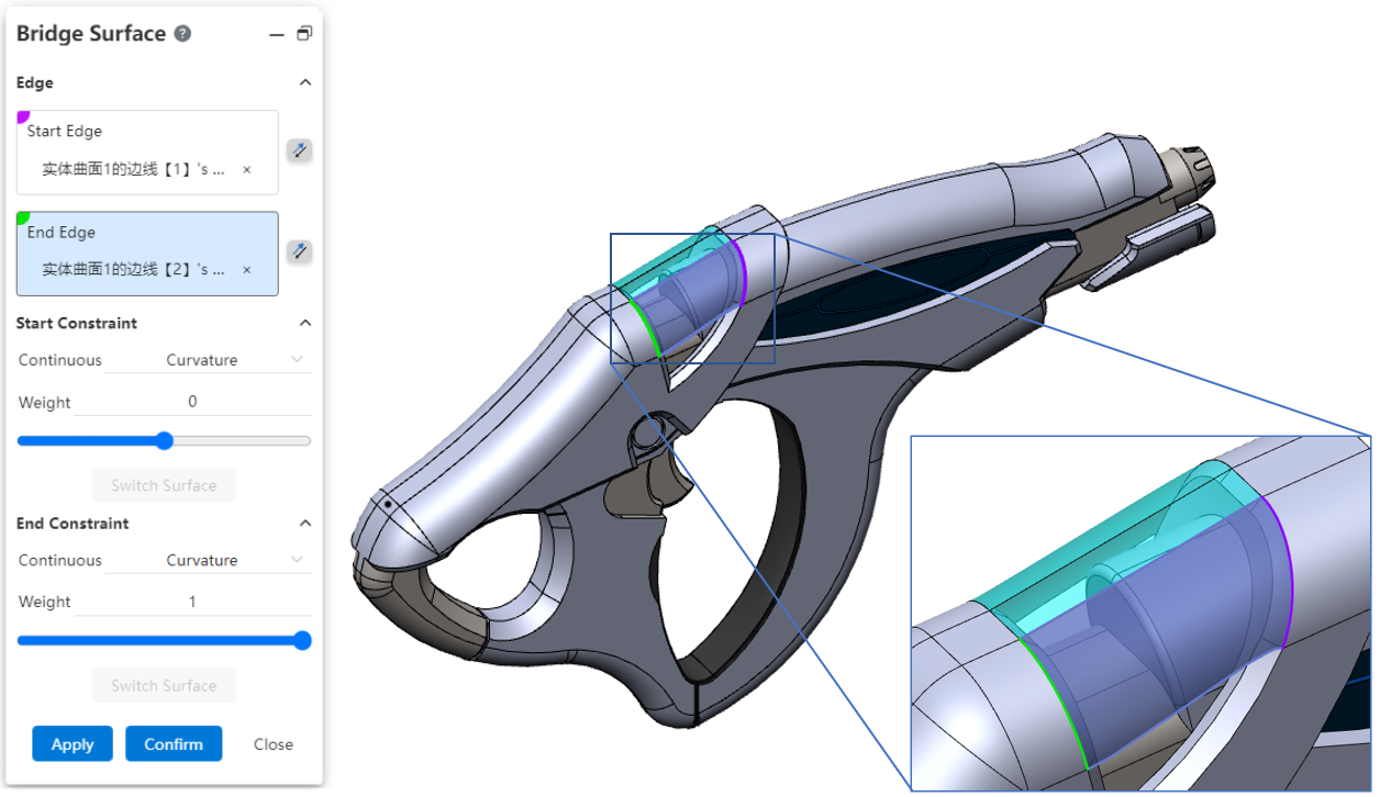
Note:
① Support the selection of edges of surfaces/entities, sketch non-reference lines, space curves;
② Only a section of the line in the edge line or sketch line can be picked up, rather than the entire outline;
③ Both edges should be either open loop or closed loop.
# Bridging Curves
New bridge curve feature, support to select two points on a line or surface to generate a bridge curve. Bridge curves up to support G3 continuous.
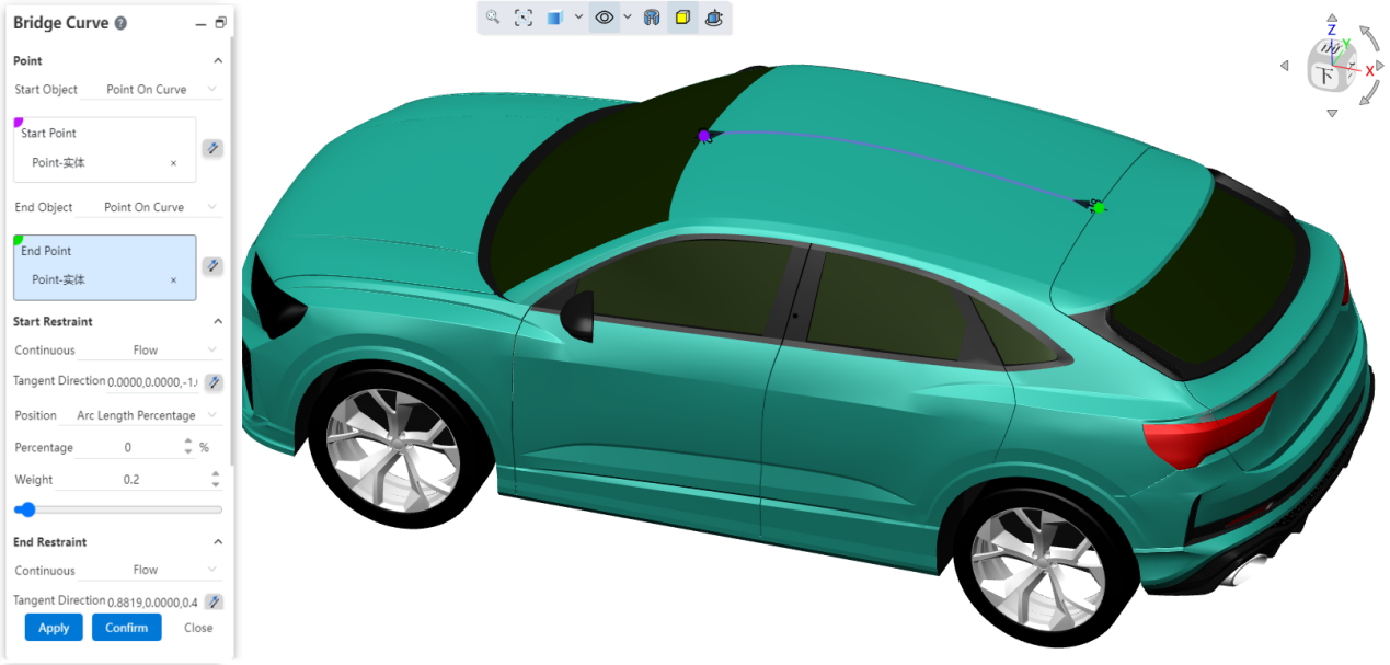
- Point requirement
- Points should be taken from a line or surface, not individual points.
- Lines include: sketch lines, space curves, surfaces/solid edges, open or closed loops.
- Surfaces include: surfaces of curved surfaces/solids, closed or open.
- Continuous mode
- Contact (G0) : The bridge curve makes contact with the line/surface where the point is;
- Tangent (G1) : The bridge curve is tangent to the line/plane where the point is located;
- Curvature (G2) : The bridge curve is tangent to the line/plane on which the point is located and the curvature is continuous;
- Flow (G3) : The bridge curve is tangent to the line/plane on which the point is located and the curvature curve is tangent and continuous;
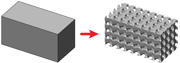
# Lattice modeling
Quickly create a "lattice model" consisting of multiple "lattice units" distributed according to certain rules in the part document.
# Creation process
- Getting Started
Toolbar switch to lattice module, click  the icon to open the lattice modeling command, and then pick up the target entity;
Set lattice parameters.
Click Preview to generate a preview with the currently set parameters.
Click OK to generate Lattice Modeling features and grid entities.
# Parameter Description
- Cell Type - Group: Set the style and size of the lattice cell.
- Shape: Sets the style of the lattice cell;
- Scale: Choose how to resize the lattice cell, optionally "uniform, non-uniform";
- Uniform (default) : the lattice unit is always a positive cube. Select this option to modify the "size" parameter and adjust the side length of the cube.
- Non-uniform: The length of the lattice unit in the XYZ direction can be set separately, and the value of the "XYZ direction" parameter can be modified separately by selecting this item to adjust the side length of the lattice unit in different directions.
- Lattice change - group: make the whole composed of lattice cells move/rotate in the target entity region.
- XYZ distance: Separately control the distance of the translation in the XYZ direction;
- XYZ Angle: the Angle of rotation around the XYZ axis is controlled separately;
- Reset: Click this button to restore the lattice position and distance Angle values to their initial state;
- Solid state - Group: Set the solid volume of the lattice, such as the thickness of the cylinder.
- Distribution: Control the solid state distribution mode, the current version can only select "uniform";
- Uniform mode: the solid state value of the whole model is consistent, and the setting item is "solid state and sliding control".
# Special note
① The "lattice" feature, like other features, supports re-editing, deleting and other operations;
② The "lattice" features have a sequential relationship with other features. When the reference features (such as the target entity) are modified, the "lattice" features change with the corresponding "grid model". When the reference feature is deleted manually, the lattice feature will be deleted together as its sub-feature;
③ The "lattice" model is the grid model, which is derived in the same way that the ordinary grid model is derived.
# Structural simulation
In the CrownCAD 2024 R1 release, the first structural simulation module allows you to perform structural simulation calculations in part documentation.
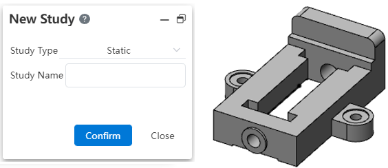
# New example
Switch the toolbar to the "Simulation" module, click  the icon to create a new example and enter the name of the example:
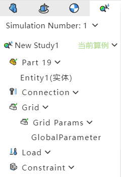
# Set the entity you want to analyze
① When multiple entities are included in a document, all entities in the document are analyzed by default;
② By right-clicking an entity in the simulation panel, you can set whether to analyze it or not;
③ Then edit the model to generate a new entity, the new entity is the entity to be analyzed by default;
④ The entity set to not analyze is not visible when the example is activated, and it does not need to consider whether it has added material, external load, and boundary information during calculation.
# Set Material
Select the entity in the simulation panel, click Apply Material  and set the selected entity to the selected material; After setting, you can view the material set by the current entity in the simulation panel.
Note:
①When the example is created, each entity inherits its material in the part document by default. Entities that do not have a separate material set inherit the document material.
②After the example is created, the material of the entity in the example can be modified by the "Apply material" command of the simulation module.
③The same entity can set different materials in different examples. Setting materials in examples does not affect the calculation of the material of the entity.
④A material must be added to each entity to be analyzed.
⑤Do not select the entity, directly use the application material function, will uniformly modify the material of all the entities in the example.
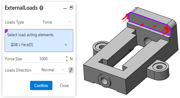
# Setting external loads
Start the external load  command, and after selecting the load surface, add an external load to the entity. Right-click the external load of the simulation panel, you can set the visibility of the load arrow in the viewport.
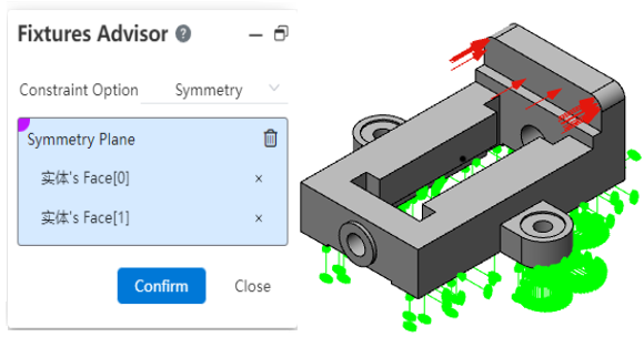
# Set boundary constraints
Click  , start the Boundary constraint command, select the fixed surface, add the boundary constraint to the entity. Right click on the boundary constraint of the simulation panel, you can set the visibility of the constraint arrow in the viewport.
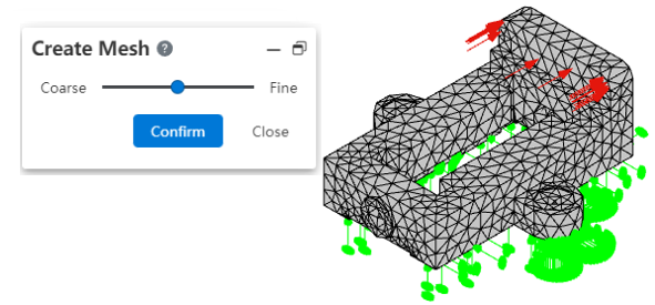
# Generate a grid
Click  to start the Generate Grid command, or right click on the grid in the simulation panel - Generate Grid and click OK after setting the precision in the dialog box.
Note:
①You can manually generate a grid for the entity before running the example;
②When running the example, if the grid has not been created yet, or if the grid is inconsistent with the current entity, the grid is automatically created or updated with medium precision.
# Run the example
Click  , execute the command to run this case.

Note:
The example cannot be paused during running, and other operations are prohibited.
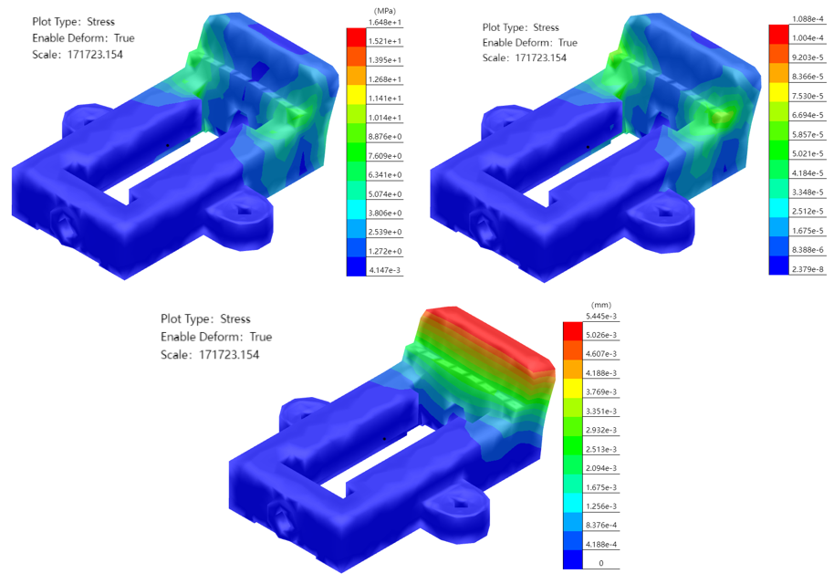
# View Results
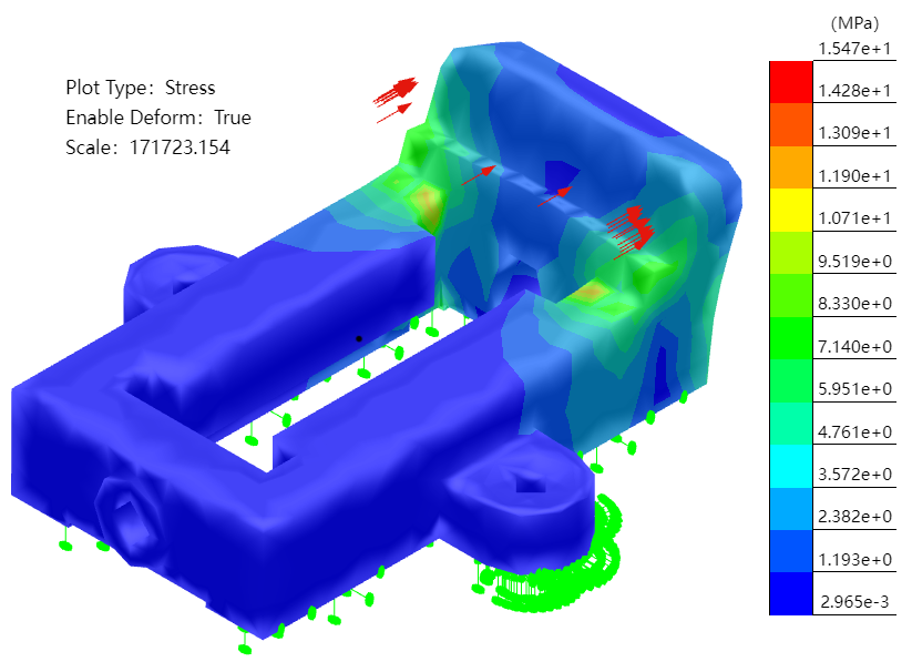
- The Stress result is displayed by default after the calculation is complete.
- Double-click on "Stress/Strain/Displacement" in the simulation panel to toggle the display results.
# Deformation results
- By default, the model will be deformed, and the degree of deformation will be increased in proportion to observe the displacement effect.
- Click
 on the command bar to turn on or off the model deformation effect.
 - Right-click the result of "Stress/strain/displacement" in the simulation panel, click Set, and change the setting mode to "Custom", you can modify the amplification ratio of deformation effect.

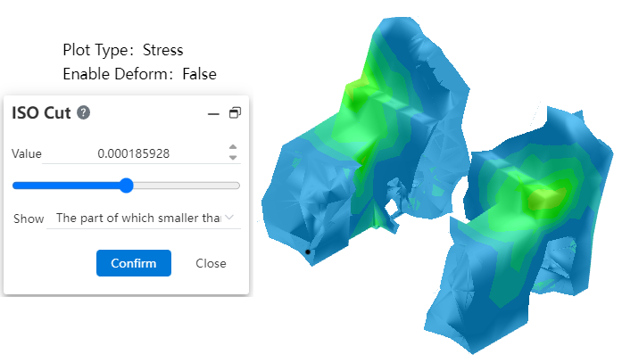
# ISO Clipping
- Click
 on the command bar's so that the result shows only areas of the model that match the parameters.
# Generate reports
- Click
 on the command bar to automatically generate and download a Word document type result report.
 - The report generation process cannot be suspended, and other operations are prohibited.

# Activate and exit the example
Automatically activate after creating a new calculator.
Double-click the example in the simulation panel, or right-click the example and select the "Activate example" option to activate the example manually.
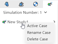
Right-click an already activated example and select the "Exit example" option to exit the currently activated example. It is recommended that you exit the example before editing the model.
Manually switching between "Feature Panel, View Panel, Simulation panel" does not affect the activation state of the example, that is, switching the panel does not cause activation or exit of the example.
After the example is created, modifying the model does not affect the generated example. You can activate the example to view historical data, or reset the example parameters and calculate the result.
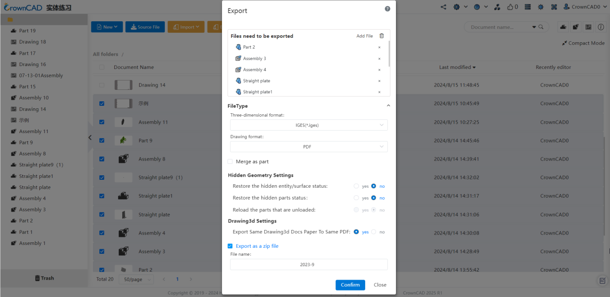
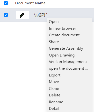
# Batch export
CrownCAD 2024 R1 adds batch export to enable batch export of models.
- Enter the document management interface, select multiple parts or assembly or engineering drawing documents, and click the pop-up button [Export] at the top to enter the export setting interface.
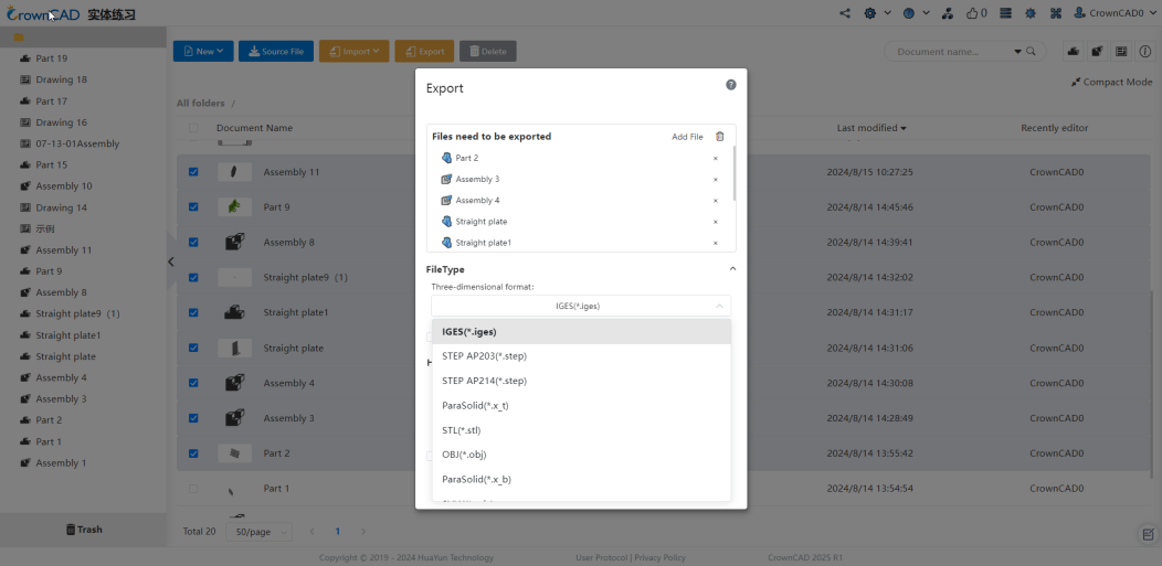
- Export rules: Users can customize the format required for 3D models and engineering drawings, and can set whether the documents are saved locally in the form of compressed packages.
- If you select only the part document, the 3D format is the same as when exporting the part separately;
- If you choose both parts and assembly, the three-dimensional format provides step, iges and other neutral formats.
# Secondary development
CrownCAD 2024 R1 adds a secondary development mode for plug-ins, supporting the use of CrownCAD secondary development interface for plug-in development, while integrating plug-ins you write into the CrownCAD platform for use.
- Creating plugins
Users can find the plug-in function entry in "Secondary Development" and click "Plug-in" to enter the plug-in management interface. Select the list of "My Creation", click "New plug-in" or "New plug-in set" to create a plug-in, and the plug-in configuration panel will pop up to configure the plug-in.
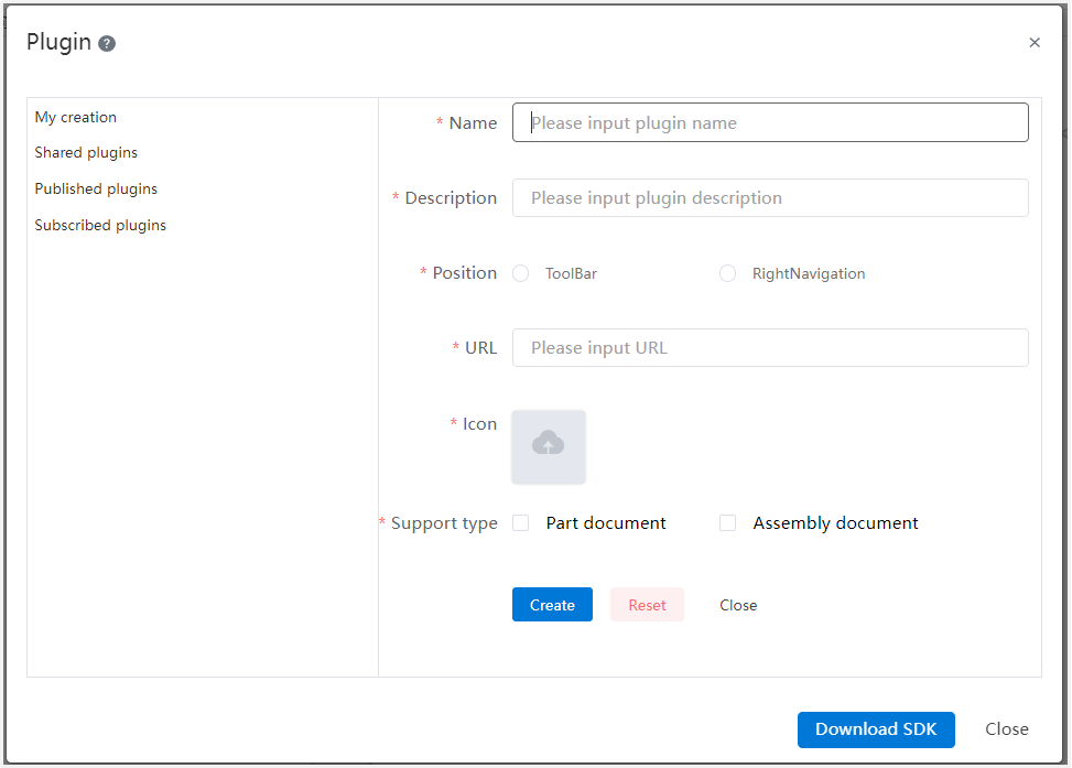
After the creation is successful, you can view the created plug-in in the "My Creation" list. Click  the button on the right of the plug-in to share, publish, and delete the current plug-in.
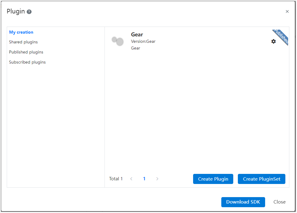
- Publish plugins
Plugins need to be released before they can be integrated into the CrownCAD platform. In the "My Creation" interface, select the plug-in to be released, click the button on the right of the plug-in, pop up the "Publish" option, click Publish, enter the released version and description information to publish the plug-in; After the plug-in is published successfully, the plug-in will display the published sign, and the published plug-in will be displayed in the list of "published plug-in".
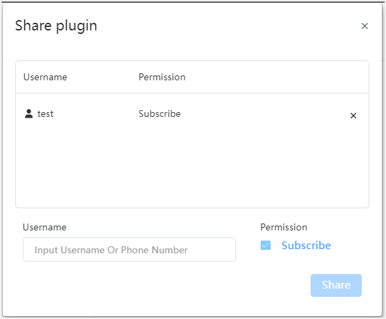
- Share Plugins
After the plugin is published, you can share the plugin with other users. In the My Create interface, click the button on the right of the plug-in, the "Share" option pops up, and click to enter the share interface; User input box type the user name or mobile phone number of the target user to share. After successful sharing, it will be displayed in the "Shared with Me" list of the shared user, and the user can subscribe and view the details.
- Subscription plug-in
You can subscribe plug-ins in the "published plug-ins" or "Shared with Me" interface, and the plug-ins will be displayed in the "My Subscriptions" list after successful subscription. You can enable, disable or delete the subscribed plug-in. After the plug-in is enabled, it will be displayed in the toolbar or sidebar. Click the plug-in icon to use the plug-in.
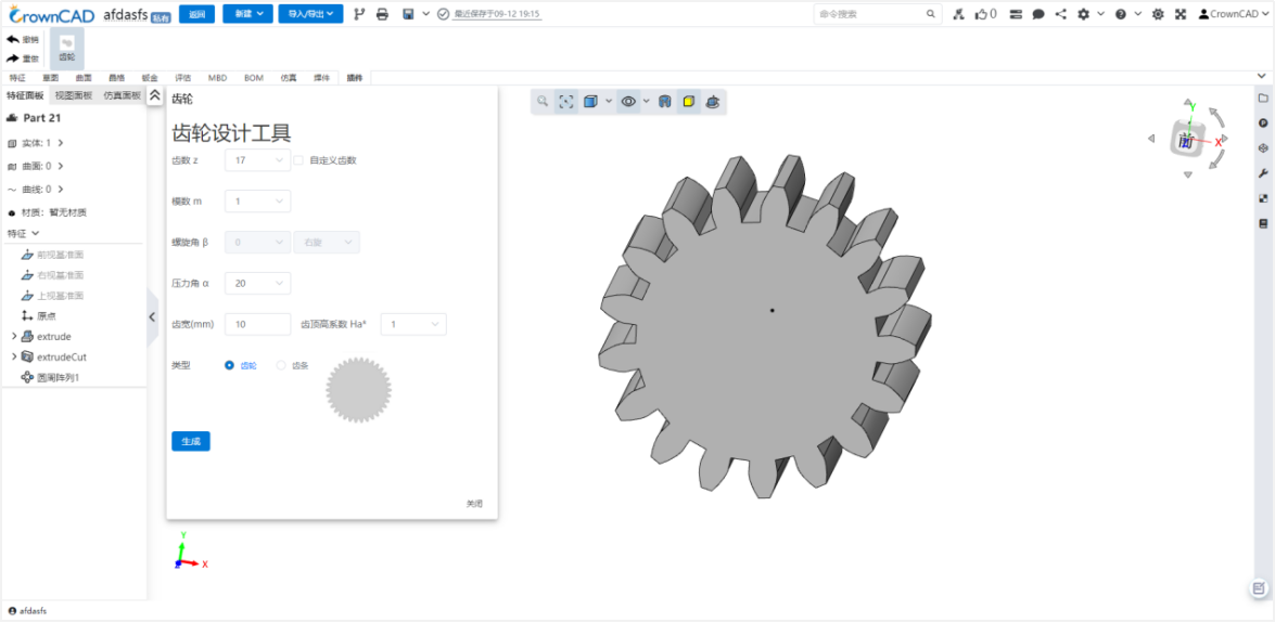
Note:Only private deployment trial is supported.
# Realistic rendering
CrownCAD 2024 R1 adds realistic rendering for higher-quality rendering of parts/assembly models, including the ability to add lights, environments, high-precision appearance maps, and export images.
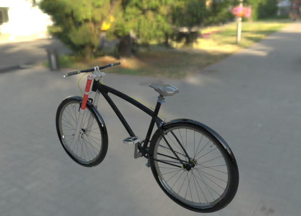
Main workflow:
1. Create realistic render
Go to the document management interface, right click the part or assembly document, click the "Create real render" button in the pop-up menu to enter the real render interface.
2. Environment Library
Click on the right [Environment library] in the real rendering interface. The environment library provides a variety of world environment data. You can right-click the world environment to add it, or drag the world environment to the viewport to add it. The added world environment will be displayed in the list on the left side of the viewport. You can open/close or delete the world environment.
3. Light Library
Click on the right [light library] in the real rendering interface, the light library provides four basic types of light sources, such as point light source, sunlight, area light source, and surface light source. Drag the light in the light library to the viewport. In the pop-up parameter box, you can customize the lighting parameters.
4. Appearance Library
Click [Appearance library] on the right side of the real rendering interface to provide the function of setting the appearance of the model. Drag the appearance from the appearance library to the model. You can choose to add the appearance to different faces/entities. The appearance has inheritance relationship. When a face of the entity has a separate appearance, delete the appearance of the face, and the face will automatically inherit the appearance of the entity.
5. Export a rendered image
Click Export render, set the parameters/format of the final exported image, click [Export] button, the current view will be automatically exported as a picture after the rendering is completed.
Note:Only private deployment trial is supported.
# The application and management of library
CrownCAD 2024 R1 adds the function of material library and model library, supporting custom material library, storage parts/assembly; Optimize the interactive mode of standard parts library, support rapid search of standard parts and increase the display of standard part attribute information.
1. Material library
See BOM- Custom Material Library for details.
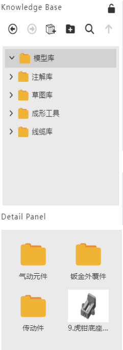
2. Model Library
Support custom creation catalog, support parts/assembly entry, call, delete, find, etc.
3. Standard parts library
Optimize the management mode of the standard parts library, and display the standard and classification on the left side uniformly; Add a search box in the upper right corner, which can quickly locate the required standard parts;
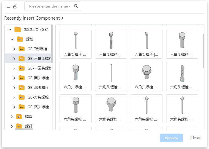
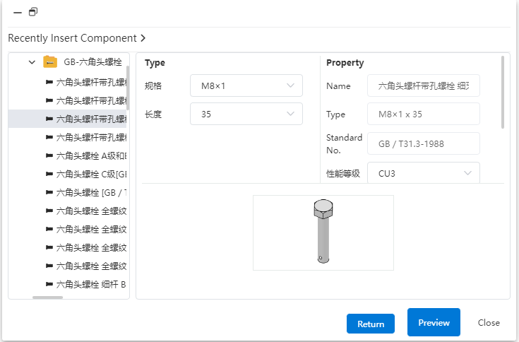
Click the detailed model, the right panel at the same time display property information and thumbnail.
# System Application
# System Settings
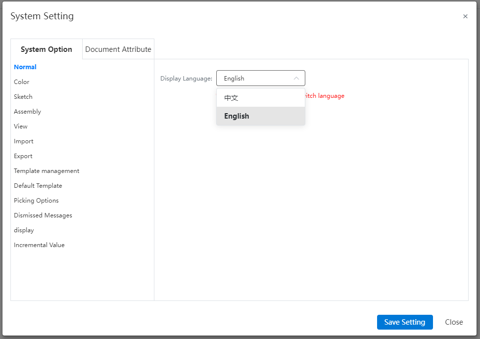
# Support Chinese/English switching
Support in system Settings - General will display language switch Chinese/English.
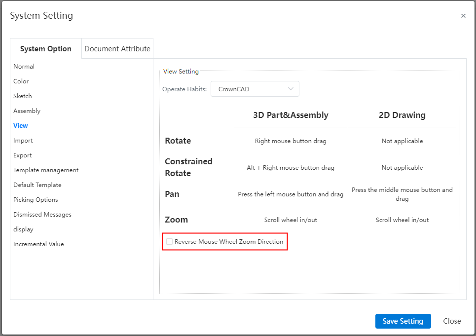
# Added the mouse reverse setting option
Support to check "Mouse wheel reverse" in System Settings - view to reverse the zooming in and out effect of mouse wheel scroll.
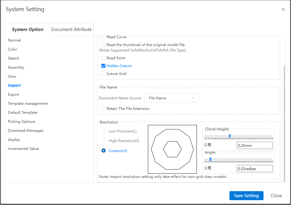
# Add import precision Settings
"Resolution" can be set in System Settings - Import, which can affect the accuracy of the imported model; Import resolution Settings only take effect for non-grid class models.
# Optimize viewport rotation operations
# Custom rotation point/axis
Click the mouse wheel on the corresponding position of the viewport to set the rotation center/rotation axis.
- To set the rotation center
Click the mouse wheel on the following table element and the mouse pointer changes to the "rotate around the point" style with the corresponding element highlighted. At this point, hold down the wheel to rotate, and the Angle of view rotates around the corresponding element.
| Type of element | Supporting elements | Correspondence center |
|---|---|---|
| Point | Solid/surface vertices, Sketch line endpoints, Sketch drawing point, Reference points, Dots | Point |
| Curves | Solid/curved edges, Sketch line, Space curve (non-linear shape) | The starting point of the line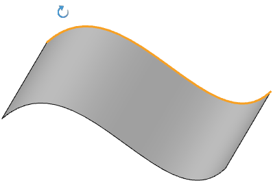 |
- To set the axis of rotation
Click the mouse wheel on the following table element and the mouse pointer changes to the "rotate around axis" style with the corresponding element highlighted. At this point, hold down the scroll wheel to rotate, and the Angle of view rotates around the corresponding axis.
| Types of elements | Supporting elements | Corresponding axis |
|---|---|---|
| Straight lines | Solid/surface edges, sketch lines, reference axes, space curves (straight lines) | Line  |
| Arc line | Solid/curved edges, sketch lines | Lines perpendicular to the plane over which the circle is located  |
| Cylindrical surface | Solid/curved cylindrical surface | Axis of cylinder 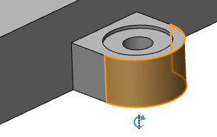 |
| Plane | Solid/curved plane-like surface (not including datum) | The line perpendicular to the face across the plane enclosing the center of the box 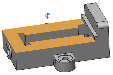 |
Note:
① After setting the rotation center or rotation axis, perform a rotation Angle operation: automatically cancel the rotation center or rotation axis, the mouse restores the default style;
② After setting the rotation center or rotation axis, do not rotate the Angle of view operation, directly perform other operations A, automatically cancel the rotation center or rotation axis, the mouse restores the default style, and perform operation A.
# Optimize the rotation focus
Place the mouse over the model, at which point the Angle of view is rotated, and the intersection of the mouse pointer with the model will be used as the center of rotation. You can still use this feature when starting any command, such as turning on the stretch boss command. In previous versions, this feature was not supported when the command was started.
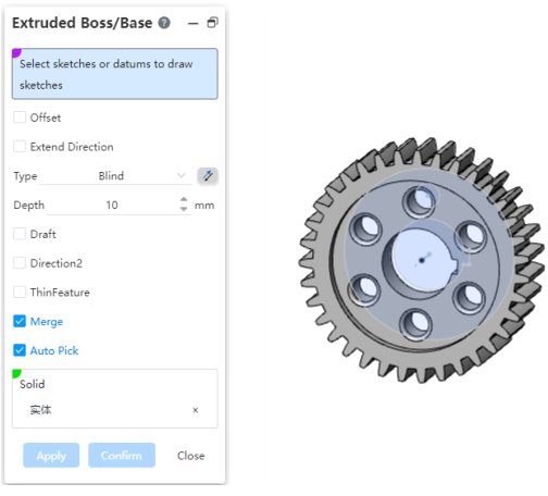
# Optimize dialog box display
# Support dialog box adjustment/recessive
- Dialog box resizing
Support horizontal, vertical drag dialog box border, in order to adjust the dialog box size.
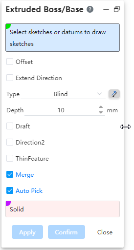
- Support dialog box visibility
When the command dialog box is opened, the "Dialog box hidden" button is displayed in the upper right corner of the feature panel and the upper left corner of the dialog box; Click the "Dialog box display and hide" button to switch the dialog box display/hide state;
| Display command dialog box | Hide the command dialog |
|---|---|
 | 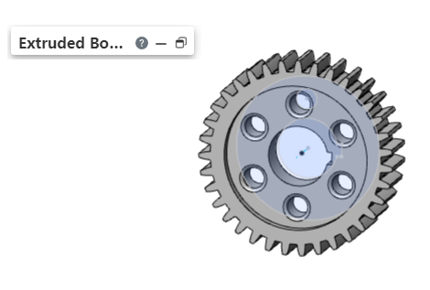 |
Note:
When the height or width of the dialog box is already the minimum value, continue to drag the dialog box in the direction of the smaller size to hide the dialog box, the hiding effect is the same as clicking the dialog box hide button.
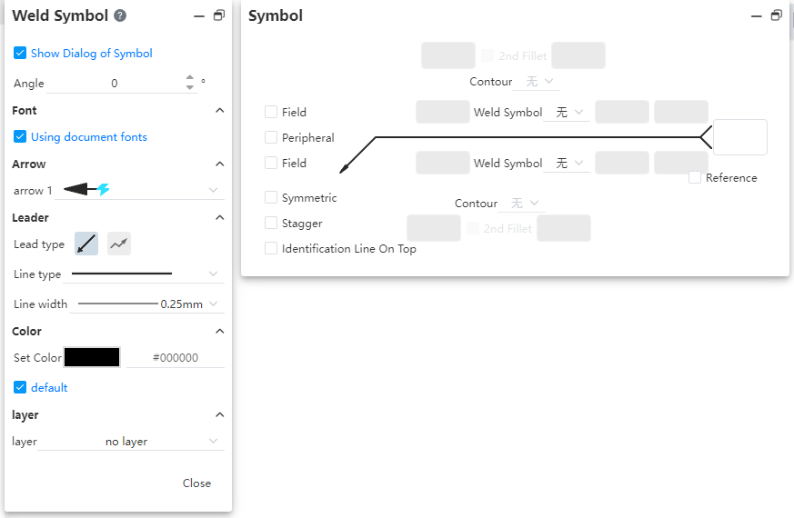
- The subsidiary dialog box supports independent adjustment of position and size, such as [welding symbol] :
# Add "Apply" button
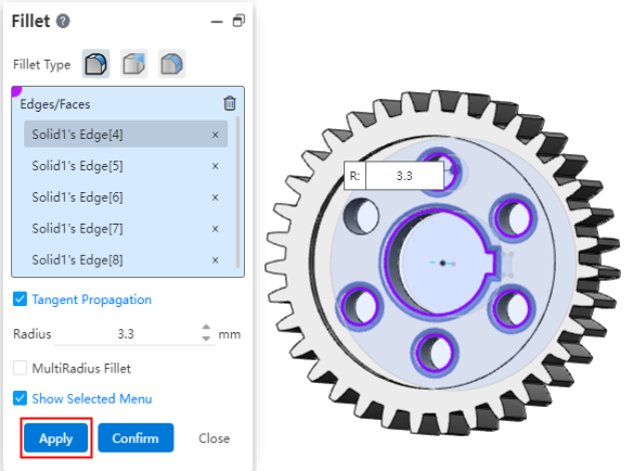
Add an "Apply" button to the command dialog box, using the rounded corner command as an example to illustrate the difference between the "Apply" and "OK" buttons:
- Application:Do not close the dialog box after creating the rounded corner, and can be created continuously.
- Ok:Create rounded corners and close dialog box.
# Optimize the pick operation
# Pick up points quickly
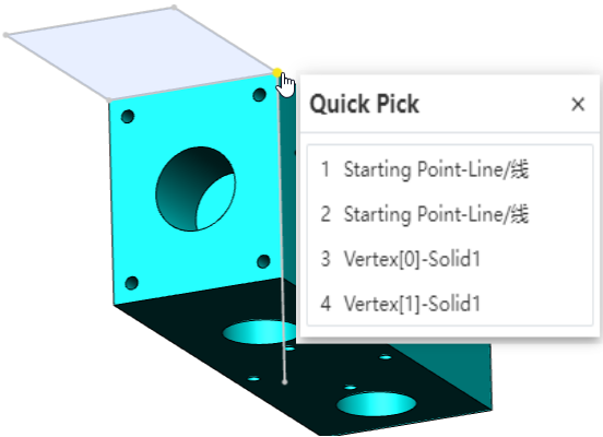
When picking up a point in the part, hover your mouse over the point a little and "... "appears in the lower right corner of the pointer. ", click the left button to pop up the "Quick pick up" dialog box, the dialog box shows all the points that coincide together here, you can click in the dialog box to precisely pick up the required points.
# Unified box selection operation
- Assembly
Hold down the left mouse button in the viewport to move the frame selection, the mouse from the left side of the viewport to the right frame selection, need to put all the instances in the frame selection range to pick up; When the mouse is selected from the right side of the viewport to the left side of the frame, as long as the instance has elements in the frame selection range, the instance is picked up.
- Parts
- Without starting command, box select can pick up surface/edge of surface/solid/grid entity. When all the edges of a surface are selected, pick up only its surface and not its edges.
- Start the command to pick up elements for a pickup frame that supports multiple selections. You can select the pickup in the viewport frame to pick up only the elements supported by the pickup frame. For example: [Delete the face] function can only select the face, but not the edge line.
# Optimize the feature panel display and right-click menu
# Align element names with features
Optimize the display names of entities, curves, surfaces, and meshes in the feature panel so that the names are consistent with the operation feature names in the last step.
Example: in the Chinese state, the feature name of the last step of an entity is "rounded corner 1", then the entity is called "rounded corner 1"; The same is true for curves, surfaces and grids.

# Perfect the right-click menu
Supplement the content of the right menu of the document at the top of the parts, assembly, and engineering drawing feature panel:
| Document Type | Menu style | Menu Options | Instructions |
|---|---|---|---|
| Parts | ICONS | Adaptive scaling | Quickly zoom to fit position and size |
| Transparent/opaque | Set document transparent/opaque display | ||
| Set appearance | Open the Set appearance command | ||
| Open drawing | Open the associated drawing | ||
| Text | Document properties | Open System Settings - Document Properties | |
| Custom Properties | Open the BOM- Custom Properties dialog box | ||
| Collapse the item | Fold all foldable items in the feature panel | ||
| Assemble | ICONS | Adaptive scaling | Quickly zoom to fit position and size |
| Hide/Show all instances | Hide/Show all parts | ||
| Transparent/opaque | Transparent/opaque all parts | ||
| Mate | Open mate command | ||
| Open drawing | Open the duplicate drawing | ||
| Text | Reverse selection | Reverse select viewport instance | |
| Insert the new subassembly | Open the new assembly command | ||
| Document Properties | Open System Settings - Document Properties | ||
| Custom Properties | The BOM- Custom Properties dialog box is displayed | ||
| Collapse the item | Fold all foldable items in the feature panel | ||
| Drawing | Text | Document properties | Open System Settings - Document Properties |
| Custom Properties | Open the BOM- Custom Properties dialog box | ||
| Collapse the item | Fold all foldable items in the feature panel |
# Set appearance/material
# Support the assembly environment to set the look
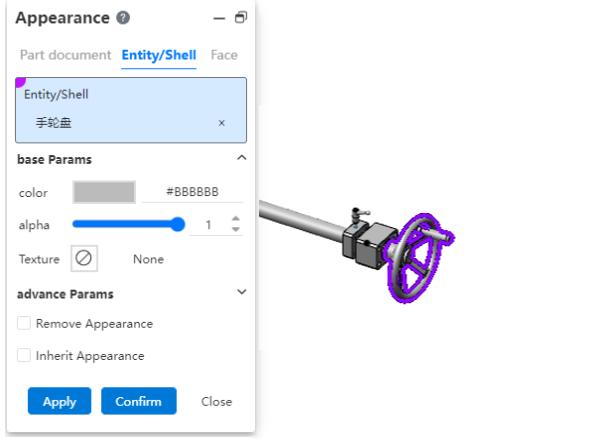
Setting appearance in assembly can set the appearance of "instance, solid/surface, surface".
Note:
① Modify solid/surface appearance and surface appearance in assembly, directly change the solid/surface appearance and surface appearance in the part.
② Setting the instance appearance in assembly changes the appearance of the entire part instance displayed in assembly, but does not change the appearance of the part itself.
③ Appearance priority: Instance Appearance > Surface Appearance > Solid/Surface appearance.
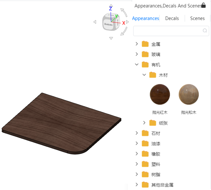
# Add appearance library
Add appearance library to provide preset appearance, such as glass, wood, etc. Each appearance corresponds to a set of appearance parameters, including information about color, transparency, etc.
How to use:
① Click  on the sidebar on the right to open the appearance library.
② Hold down the left mouse button and drag the preset appearance onto the element you want to set the appearance on.
③ Release the left mouse button and select which level you want to set it to in the menu that pops up to complete the setup.
# Sketch Drawing
# 2D Sketch
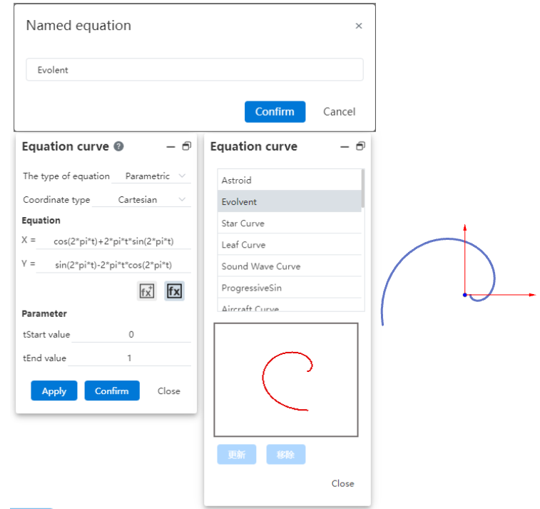
# Equation curve
In this tool, new equation library and save custom equation function, and support to edit the created equation curve:
- Equation library
You can select an existing equation in the library, or add a custom equation to the equation library for quick subsequent calls;
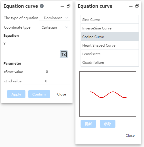
- Examples of calling equations:
Double-click an equation in the equation list to fill it into the left Equation dialog box and preview it in the viewport:
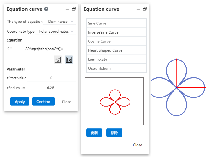
Equation parameters can be adjusted to generate a new equation curve:
- To save a custom equation:
After filling in the equation, click  to add the equation to the equation library, and return to the corresponding list according to the equation type;
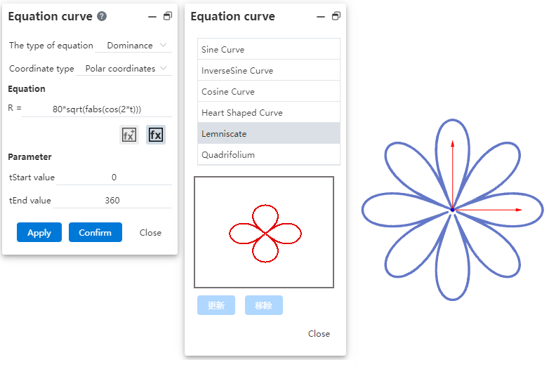
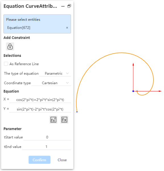
- Edit the equation curve:
Click the created equation curve, the "Equation curve properties" dialog box pops up, you can adjust the equation or other parameters again;
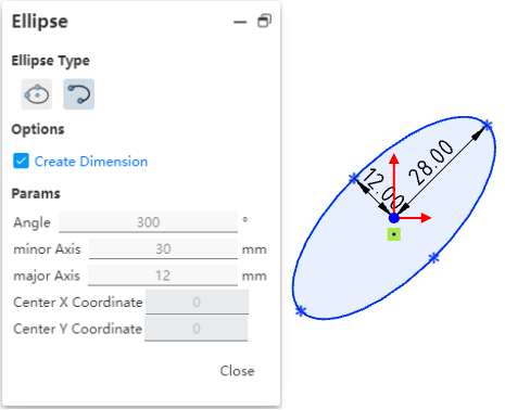
# Ellipse/ellipse arc
New ellipse/ellipse arc function, generate ellipse outline in sketch by defining Angle, radius 1, radius 2, center of circle coordinate parameters.
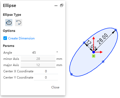
Note:
① After creating the finished ellipse, drag and drop can only change the position, can not change the size and Angle of the ellipse, the size of the ellipse can only be changed by editing the size.
② If there are any size or geometric constraints in the ellipse, it is not supported to continue to adjust the size in the property box.
# Dimensional labeling
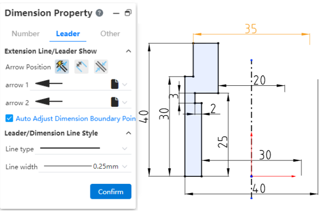
# Marking symmetrical dimensions
This action helps you label points, lines, circles, arcs to 2 times the size of the center line/guide line in the same sketch, and supports switching sizes.
- Marking symmetrical dimensions:
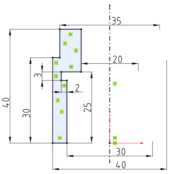
① Label two elements with the "size Constraint" command, one of which is the center line/guide line; ② If the size number is placed beyond the center line, it will be labeled as symmetrical size;
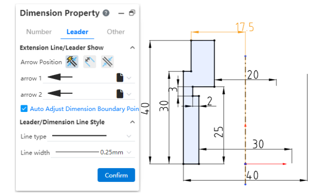
- Change size type:
After generating a symmetrical size, change the size to a radius size or a diameter (symmetrical) size through the properties panel for the size - Diameter/Radius.
# Label the 0 value dimensions


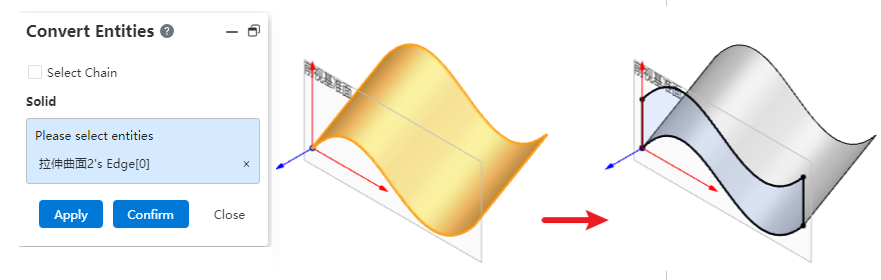
# External Reference
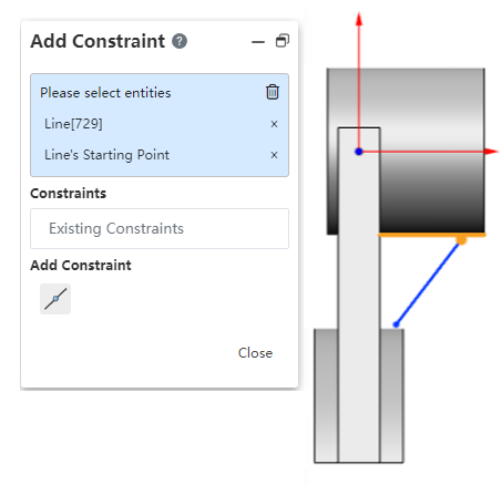
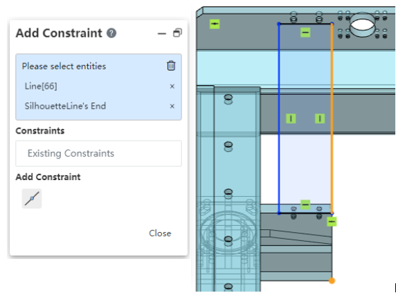
- Reference silhouette/round edge line to add constraints:
When adding constraints, support to directly select the external element's silhouette or circle edge line for annotation, without first projecting.
| Add geometric constraints to side projection contours | Add dimensional constraints with side projection contours |
|---|---|
 |  |
- Supports direct labeling of the plane perpendicular to the current sketch plane without the need for a projection first.
# Offset
Expand the support type of elements to be offset, can directly select the elements outside the sketch for offset, and keep the linkage.
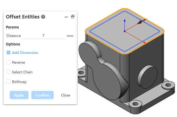
Note:
① Optional other sketch lines, solid/surface edges, solid/surface surfaces (equal to picking up full edges); ② When the selected element cannot be projected on the current sketch surface to generate a line that can be migrated, the prompt "cannot migrate this element" is displayed; ③ Automatically add dimension labels and "offset" constraints between the offset line and the selected element (circle and curve elements are not supported).
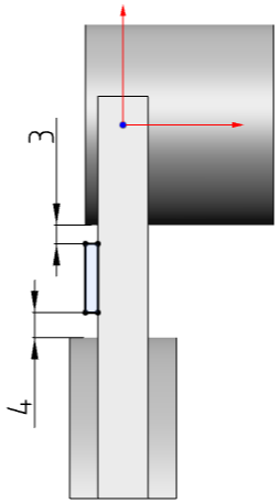
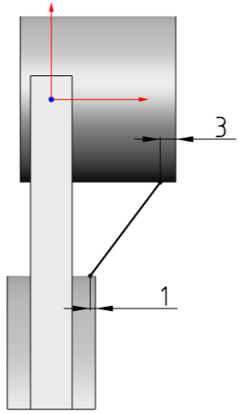
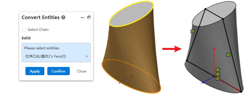
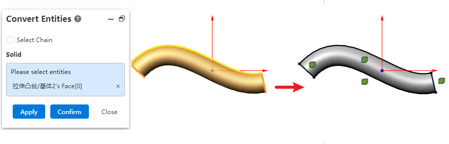
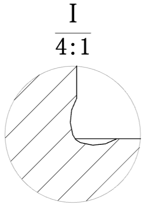
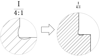
# Transition boundary
Support the choice of spline surface conversion boundary, repair lofting boss, spline curve conversion effect.
- Spline surface conversion boundary:
- Example of lofting boss, spline curve conversion effect:
# Applicability
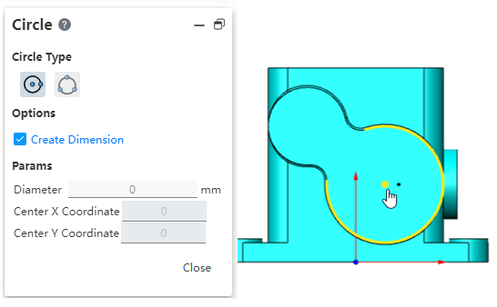
# Annotate overall scaling for the first time
When the length or distance in the sketch is first annotated, the elements and perspectives within the sketch are automatically scaled around the origin of the sketch, and they look the same as before the annotation, but the length/distance of the relevant elements have changed.
# Pick Up Optimization
- Support for picking center points:
In the sketch environment, when executing the sketch drawing class command, you can directly pick up the center of the sketch circle/arc edge line, and automatically add coincidence constraints. There is no need to convert the boundary first and then pick up.
- Support for pre-selection of elements:
Sketch state, do not open any command, highlight when the mouse points to the face, line, point, sketch and support picking; After pre-picking elements, open the corresponding sketch command:
- If the command supports pre-picking elements, then automatically fill the corresponding pick box;
- If the command does not support pre-picked elements, when clicking other elements in the viewport, unhighlight and select the pre-picked state;
# 3D sketch
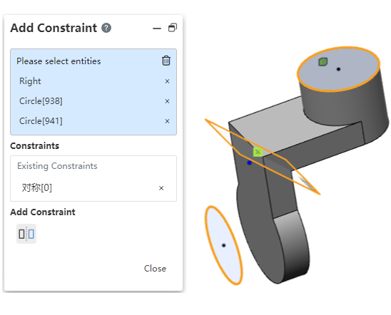
# Symmetric constraints
Adding symmetric geometric constraints to the 3D sketch environment adds symmetric constraints to two elements relative to a plane.
# Applicability
# Automatic direction judgment
In 3D sketch environment, the direction of the plane will automatically switch to the most closely parallel view direction when the view direction is almost parallel to any plane of the XYZ coordinate system.
After the automatic switch, you can still manually switch to other standard three-view directions using the tab key.
# Parts and Features
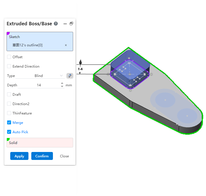
# Support for multi-profile drawing
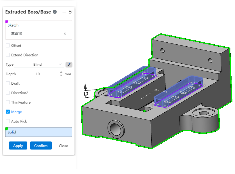
Now, the stretch convex plate function supports stretching multiple non-intersecting contours at one time. With this foundation, you no longer need to perform a dissection operation of text before stretching the sketch text directly.
Note:
- Entities created by stretching multiple Outlines at once appear to be separate from each other, but they are counted as one entity in the system.
- This type of entity with multiple disconnected parts is not allowed to be removed from the shell.
- Pick up the sketch line in the viewport and the system will stretch the closed outline where the sketch line is located. If multiple Outlines are included in a sketch, you can use this feature to specify which Outlines to stretch instead of having to stretch all the Outlines of the entire sketch. This function is applicable to stretch bosses, stretch excise commands.
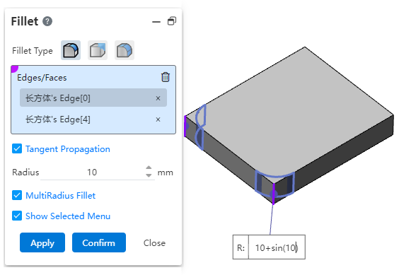
# Fillet radius parameters support variables/equations
When creating a multi-radius fillet, you can enter variables or equations in the multi-radius input component; You can edit the variables or equations after they are created.
# Hole - anchor point enhancement
In this version, the selection method of the hole anchor point is mainly enhanced: when selecting the hole center point, the whole sketch can be directly selected or the sketch can be quickly "drawn".
1)The hole center point supports the selection of the entire sketch:
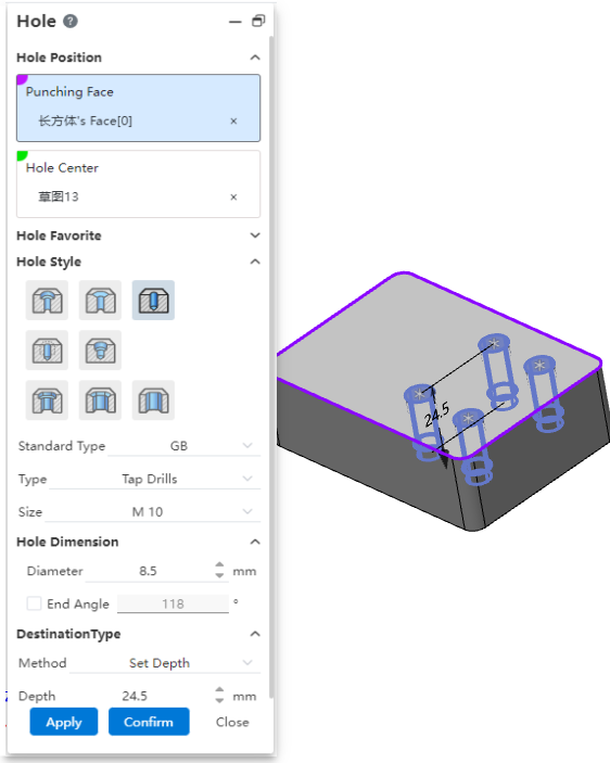
2)Quick "sketch" when elements are not picked up.
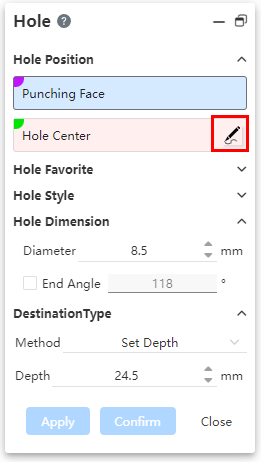
Click "Draw Sketch"  to create a new sketch on the selected solid face to punch and enter the sketch, exit the sketch when it is finished, and fill the entire sketch to the "hole Center Point" pick box.
# Add a Center of Mass
Support for centroid generation in parts/assemblies, support for centroid reference points generation in parts.
1)Centroid creation method:
By clicking the command "Center of Mass" or "Quality Properties" - "Show center of mass", you can create the center of mass; There can only be one center of mass in a document.
2)How the centroid reference points are created:
After the centroid is generated, right-click the centroid feature in the feature panel and click  the icon to create the centroid reference point. You can have more than one centroid reference point in one document.
3)The difference between a centroid and a centroid reference point:

- The centroid represents the final centroid position of the entire document. This can be generated in assembly and parts
- The centroid reference point represents the centroid position in the modeling history of the model up to the time the centroid reference point feature was created. It can only be generated in the part.
4)In most cases, the position of the centroid point and centroid reference point is updated instantly as the model changes. In some special cases, it may not be possible to update automatically, at this time, the update button will be displayed after the centroid, click to manually complete the update.

# Add Save entity
New Save Entity feature that allows you to copy and save entities from one part document to the new part document. This feature also allows you to insert these new part documents into a new assembly document.
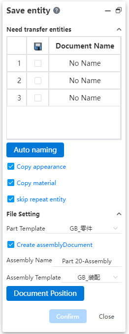
1)To save to a new part document:
Uncheck "Generate Assembly Document" to copy and save the selected entities to the new part document separately.
2)To generate the assembly document:
Check "Generate Assembly Document" to create an assembly document directly and insert all the selected entities into the assembly document as new parts.
3)Other save options instructions
Copy appearance Settings: Apply the appearance of the entity in the source document to the new part entity;
Copy Material: Applies the material of each entity in the source document to the document material of the new part.
- When transferring an entity with a separate entity material set, copy the entity material onto the document material of the corresponding new part.
- When transferring an entity without a separate entity material, if the source document has a document material, copy the document material to the document material of the corresponding new part;
- When transferring an entity that does not have a separate physical material set, if the source document does not have a document material set, the document material for the new part is not set.
- Transfer the material to the document material of the new document, rather than the physical material, so that the material properties can be read through the material specification table during assembly.
Skip Duplicate entities: Check this, "Array-generated entities, Duplicate Entities in Weldparts Cut List items" will generate only one part document, avoiding the need to create multiple duplicate documents.
# Assembly design
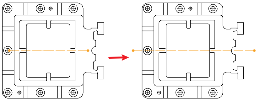
# Optimized assembly image
The assembly image parts follow the left hand coordinate system, and the new "create new document" option supports the creation of different image effects.
Note: Checking the option will generate a symmetrical part document.
| Check | Untick |
|---|---|
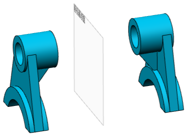 | 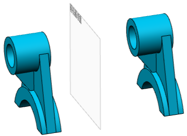 |
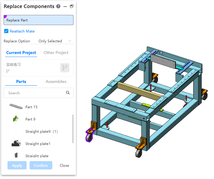
# New replacement parts function
Added Replacement parts function, which allows you to quickly replace parts or sub-assemblies in the assembly. After replacement, the new part position coincides with the original part reference position.
# Enhanced TopDown external reference
When editing parts in assembly, part features can pick up elements of other parts (points, lines and surfaces) as feature directions, termination surfaces, etc.
The features and picks that support references to other parts elements are listed in the following table:
| Command | Pick-up items |
|---|---|
| Sketch | Datum, plane, or sketch |
| Sketch size constraints, geometric constraints | Can be with other parts of the solid boundary line, sketch line and other constraints, optional items and select the current part sketch outside the elements for constraints |
| Stretch boss | Shape to end of face 1 |
| Shape to end of face 2 | |
| Orientation | |
| Rotating boss | Shape to end of face 1 |
| Shape to end of face 2 | |
| Stretch the surface | Shape to end of face 1 |
| Shape to end of face 2 | |
| Direction | |
| Stretch cut | Shape to face end face 1 |
| Shape to end of face 2 | |
| Orientation | |
| Rotary cut | Shape to face end face 1 |
| Shape to end of face 2 | |
| Linear array | Directions 1 and 2 |
| Circular array | Shaft |
| Curve array | Curves |
| Sketch array | Sketches |
| Packed array | Fill Borders |
| Direction |
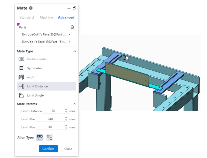
# Advanced mate - Distance/Angle limiting mate
Supports a restricted fit, allowing parts to move within a certain numerical range of distance or Angle mate.
# Mechanical mate - Notch mate
Supports you to fit the "cylinder/shaft" to the "straight mouth/arc groove", or the groove to the groove, and supports "free", "in the center of the groove", "percentage along the notch" and "distance along the notch" a variety of constraints.

# Add large assembly mode
You can use Large Assembly mode to improve the performance of large assembly models.
How to open it:
- Automatic opening: Automatically judge the size of the model when opening the model, pop up a prompt for large assembly, and can choose whether to open in large assembly mode.
- Manual opening: Right-click the assembly document in the document list and select the "Open in large assembly mode" option to manually open the assembly document in large assembly mode.
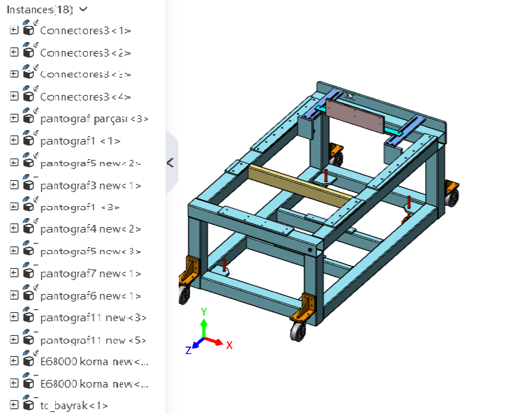
In large assembly mode, feather display is added to the instance icon, indicating that the instance is currently in lightweight display state.
Right-click the instance in the instance list (multiple selection is supported) and click "Restore lightweight" to switch the instance to the precise display state. The model that has been accurately displayed cannot be switched to the lightweight browsing again.
# Application enhancement
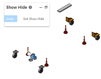
# Show hidden parts
Added the "Show Hidden Parts" tool to temporarily swap the hidden states of parts in order to see which parts are currently hidden.
By clicking on a part in the viewport, you can change the previously hidden part to the displayed state.
# Drawing
# Views
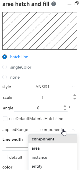
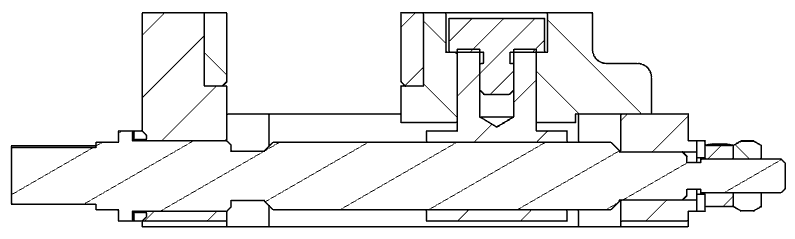
# New section line style
1)Support for modifying section line styles
For the generated section view, the section line style can be modified according to the scope of parts, regions, instances and entities, as shown in the following figure, modify the section line style within the scope of the region:
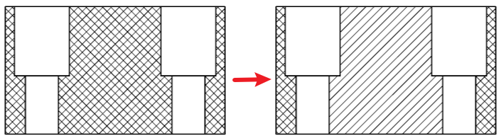
2)Section lines are directly distinguished in different bodies
Improve the intuitiveness of the section view of multi-entity, assembly and other parts, and adopt different section line angles and densities for different entities and the section lines of two adjacent parts in the assembly.
# Optimize local view
1)Support for creating local views on a section view:
Support section view as the parent view to do local view.

2)Support editing local view scope:
The completed local view supports editing and modifying the boundary outline of the local view; After the modification is completed, the central position of the local view remains unchanged, and the content of the view is updated.
# Add a disconnected section view
Support to add the disconnecting section view feature on the existing view, section open part of the display view; And support to edit the section area.

# New cropping view
You can use the sketch to draw a sketch of the crop area you want to keep on the view, then select that sketch and click Crop View to finish creating the crop view.
1)Crop area sketch requirements:
- The sketch should be a single enclosed area;
- The sketch should belong to the current view.
2)Cropped view features Supported and unsupported views:
- Supported views: Model view, projection view, Section view, auxiliary view;
- Unsupported views: local view, local view of the parent view, split view;
- Do not support the clipped view for the parent view to make a section view or local view
- When using the cropped view as the parent view to make projection view and auxiliary view: the sub-view is a complete model;
# Optimize sheet metal plate mode engineering drawing
When there is only one sheet metal model in the selected part, you can create a sheet metal plate type view that supports the generation of bending lines and the addition of bending comments.
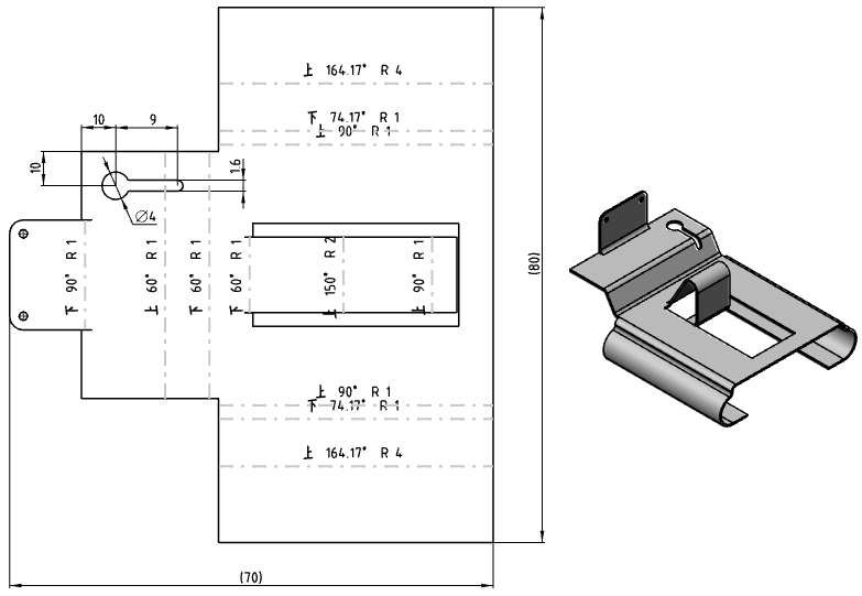
1)Bend note description:
- The premise of generating a bending note is to generate a bending line;
- Enter keywords and text in the text input box of the dialog box, and display the bending parameters and text corresponding to keywords in the bending note;
- The default bending comment content is "bending direction bending Angle R bending radius";
- The "Bend comment" text box in the model view dialog box controls the content of all bend comments in the view. Modify this item, change the content of all comments;
- You can double-click the bending comment in the viewport to modify the content of a single bending comment;
2)Bending parameter description:
| ICONS | Parameters | Instructions | Key Words |
|---|---|---|---|
 | Bending direction | Bending direction relative to current viewing Angle: up, down | <bend-direction> |
 | Bend corner | Bend Angle | <bend-angle> |
 | Supplemental Angle | The supplementary corner of the bend corner | <bend-complementary-angle> |
 | Bend radius | Bend radius | <bend-radius> |
 | Bend order | Bend order | <bend-order> |
 | Bending coefficient | Bending coefficient | <bend-allowance> |
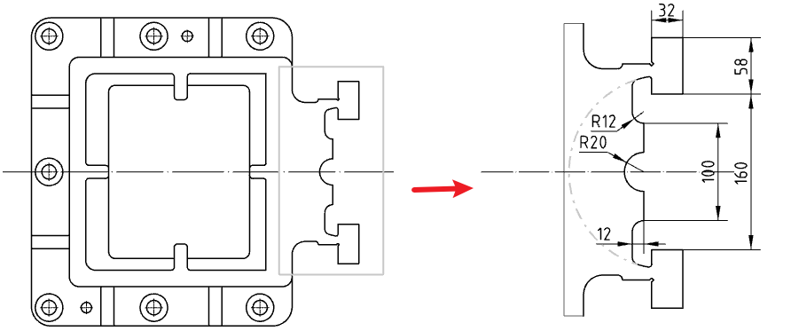
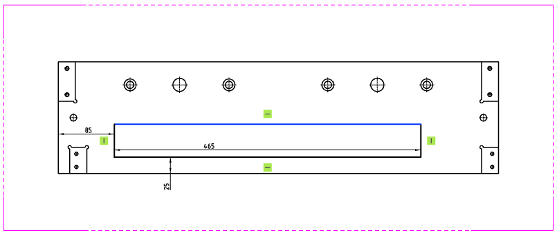
# New Sketch projection
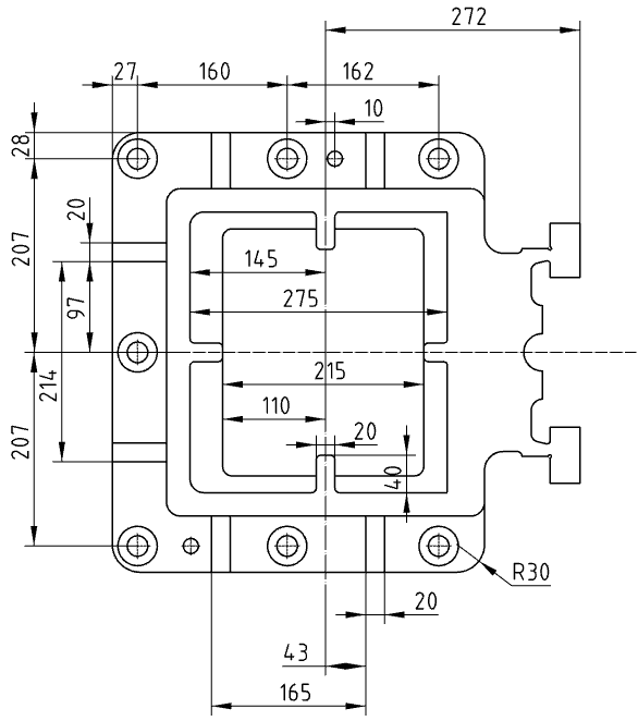
Support the sketch of the part model displayed in the engineering drawing view, and the displayed sketch can be dimensioned, which allows you to mark the frame size of the welded part more intuitively.
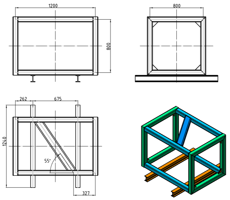
The sketch can be dimensioned, and the annotation effect is the same as the annotation model edge line and the driven size;
When the view is generated, the default implicit state of the sketch is as follows:
- 2D Sketch: The sketch plane and 2D sketch parallel to the projection direction of the view are hidden by default when the view is generated, regardless of its implicit state. The implicit state of other 2D sketches is the same as the implicit state of the sketch in the model when the view is generated.
- 3D sketch: The implicit state of the 3D sketch is the same as the implicit state of the sketch in the model when the view is generated.
When a view is generated, each view independently records the explicit state of each sketch in that view.
- The model features in the view panel can be expanded, and the eye icon after the sketch can be clicked for the hidden operation;
- This operation only affects the hidden state of the sketch in the current view, and does not affect the hidden state of the sketch in the source model and its parent and child views.
# Added Reading 3D Explosion View
The assembly engineering drawing supports the generation of the view of the explosion state, and supports the normal marking size, part serial number, etc., on the explosion view.
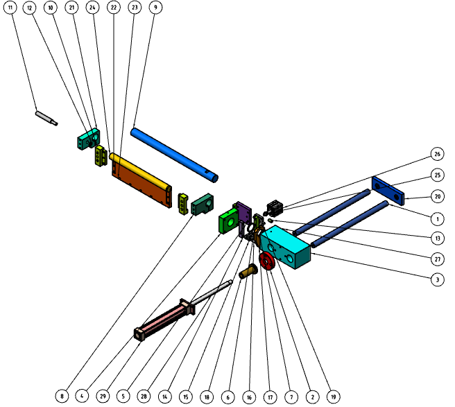
Note:
① When the assembly is selected, the explosion view of the isometric direction is displayed in the view palette. If there are multiple explosion views, the recently activated explosion view is displayed;
② The explosion view supports custom view, which is generated on the basis of the model after the explosion after modification.
# Comments
# Enhanced centerline functionality
This version has enhanced the centerline function, you can manually drag the centerline endpoint to modify its length; And the centerline can be selected when adding annotations such as size and roughness.
1)Manually modify the centerline length:
Select the center line that has been generated, the line is highlighted, hold down the two ends and drag along the direction of the center line to change the center line length.
Note: The centerline that manually modifies the length will no longer change the length as the model changes.
2)Select the centerline to add a note:
Use the smart size class command to mark, you can select the center line and other points and lines in the view to mark.
Mark with commands such as roughness, part serial number, reference, etc. that can be anchored to the side line, and you can choose the center line as the anchoring element.
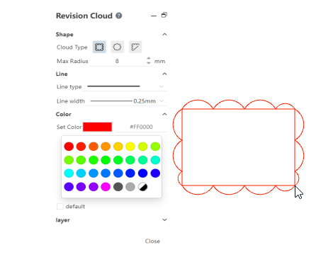
# New revision cloud tool
Support for designating closed reference areas in drawings, forming revision cloud patterns, and creating revision cloud annotations in views.
1)Specify reference areas
Specify the closed guide area by adding connected arcs on the side of the guide area to form a revised cloud pattern.
2)How the guide line area is specified
- Rectangle: Specify the two diagonal points of the rectangle, with the guide line area being rectangular;
- Ellipse: specify the center of the ellipse and a vertex of the rectangle surrounding the ellipse in turn, and the reference line area is an ellipse;
- Polygon: Specify the vertices of the polygon in turn, and the reference line area is a polygon;
3)Edit the guide area:
- Check the existing revision cloud to show the control points of the guide path that can be dragged and dropped to change shape. Different shapes show different control points;
- Rectangle: The four vertices of the rectangle, which control the length and width of the rectangle. The center point, controls the position;
- Oval: the apex of the outer rectangle, which controls the length and width of the outer rectangle. Center point, which controls the position;
- The vertex of a polygon, which controls the position of a single vertex of the polygon;
- The resulting revision cloud pattern can be viewed as a special sketch block that can be moved, re-edited, and deleted as a whole.
# Versatility
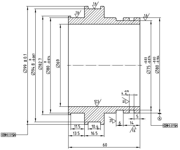
Optimized annotation reference limit, support to add surface roughness, form and position tolerance, reference feature annotation on dimension line and dimension boundary line. Pointing surface elements are automatically turned into points.
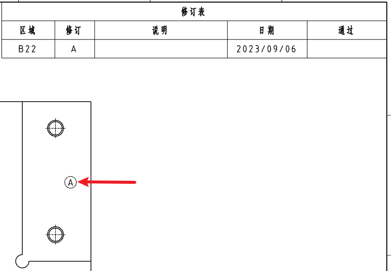
# Table - Revision table
Add revision table, revision symbol function, support to generate revision table and associated revision symbol in the drawing.
Note:
① The default anchor point of the revision table is located in the upper right corner of the frame;
② Insert a maximum of one revision table into each engineering drawing;
③ The revision table must be inserted and at least one row created in order to use the revision symbol command. Otherwise the revision symbol command is gray and unusable.
# Added in-view sketching
Double-click the view, lock the focus of the view or right-click the view to lock the focus in the viewport/view panel, select "view lock focus", and switch the view to the lock focus state, you can draw a sketch in the view reference view element, each sketch command is used in the same way as drawing a sketch on the drawing.
Note:
① The sketch drawn belongs to the lock focus view;
② The length of the sketch line in the view considers the view scale;
③ The sketch line belonging to the view or drawing can only be picked up and dragged to modify the position when the corresponding view/drawing is in the locked focus state, otherwise the sketch line cannot be picked up;
④ Sketch lines that belong to views, when the view moves, move with the view as a whole.
# Optimize dwg/dxf format export
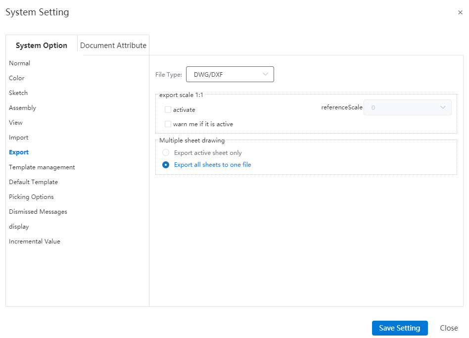
# Support 1:1 ratio output engineering drawings
When exporting the engineering drawing in DWG/DXF format, you can select the drawing or a certain view proportion, reverse scale the entire drawing, so that the exported engineering drawing model line length is consistent with the actual length; You can set whether to activate this function in system Settings - export.
# Applicability
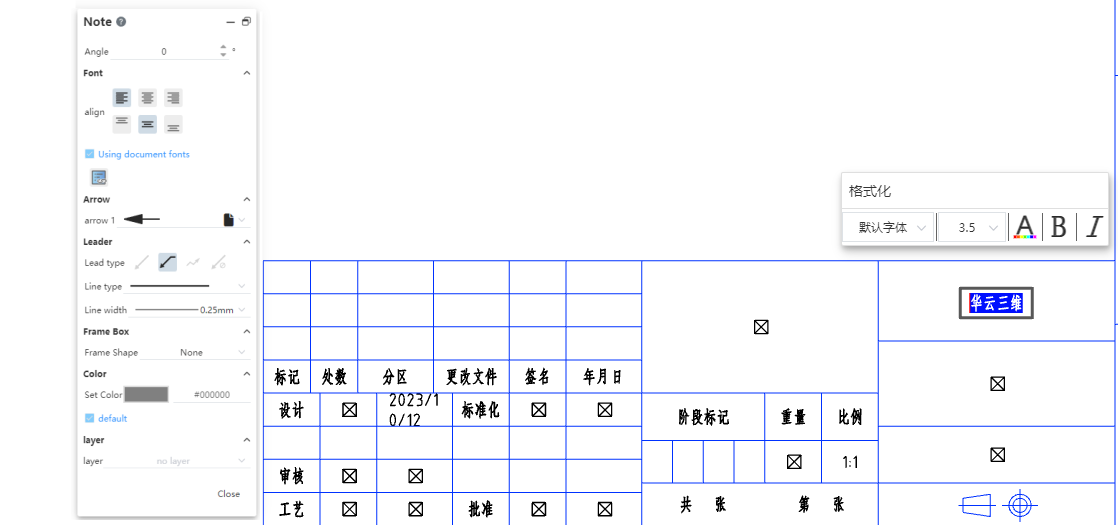
# Optimize title bar editing
When editing the format of the drawing, you can modify the content and format of the text in the title bar.
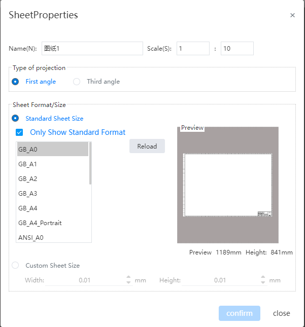
# Support custom drawing scale
Support for setting the drawing scale to the desired scale, which can be achieved in two ways:
- Click the "Drawing scale" button in the lower right corner of the interface to choose to switch the drawing scale or select "User-defined" to manually enter the drawing scale;
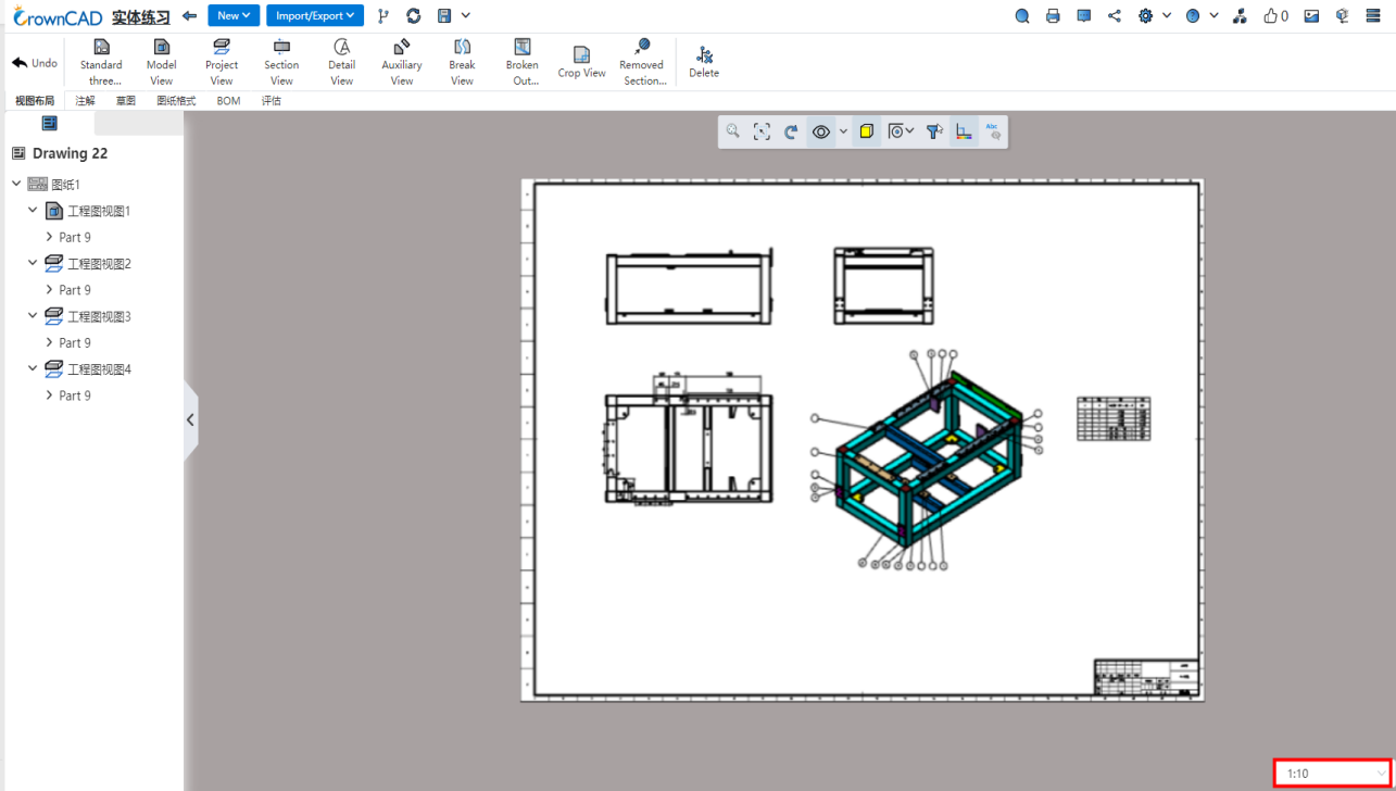
- Right click the drawing in the view panel, select "Properties", and modify the drawing proportion in the pop-up "Drawing Properties" dialog box.
# Optimize the Right click menu
Optimize the right-click menu.
- Right-click an empty space inside the view
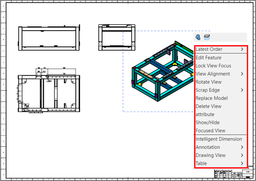
| Menu contents | Effects |
|---|---|
| Recent command | Point to the second level menu that pops up after it, where the most recently used commands are displayed.Note: This item is displayed after using any command, not when never using a command. |
| Editing feature | Edit the properties of the current view. |
| View lock focus | After the view locks focus, the sketch will lock with the view. |
| Align the view | Unalign and default align. |
| Trimming | You can choose to show or hide cut edges, which are not shown by default. |
| Replace the model | Choose other 3D models to replace. |
| Delete view | Delete the current view. A confirmation dialog box should pop up before deleting |
| Properties | Edit the properties of the current view. |
| Show/Hide | Control the visibility of the selected view. |
| Enlarge the selected range | Automatically center the viewport on the selected view. |
| Smart Sizing | Click to launch the Smart Sizing feature |
| Annotations | The second level menu pops up after pointing, which displays the annotation function such as text annotation and weldpart symbol. |
| Engineering view | A secondary menu pops up after pointing, in which view functions such as model view and projection view are displayed. |
| Table | A secondary menu pops up after pointing, which shows table functions such as summary table and material detail table. |
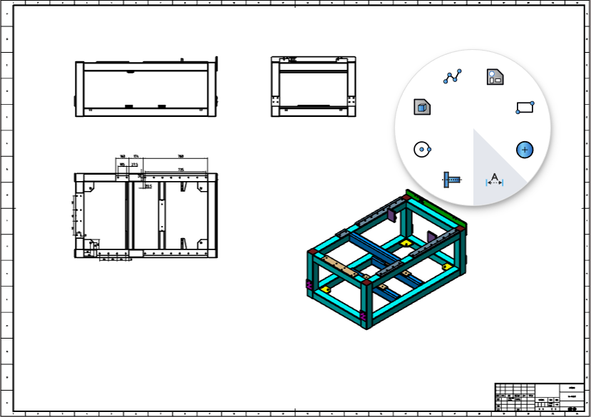
# The engineering drawing environment supports mouse gestures
Support the use of mouse gestures in engineering drawings.
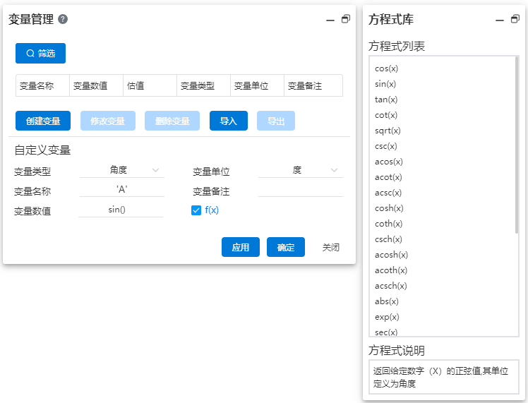
# Variable management
# Increase equation library
The "Equation Library"  option is displayed in the Variable Management section, and all functions supported by the current system are displayed when checked.
- Click on a function to display the description of the corresponding function.
- Double click the function to quickly add it to the Variable Value input box.
# Evaluate
# Quality attribute Enhancement
1)Application enhancement
Click the document name at the top of the feature panel to fill the current document into the pick box, the same effect as clicking the "Select Current Document" button.
2)Add the "Center of Mass" option
Dialog box added "Show Center of Mass" option for creating center of mass.

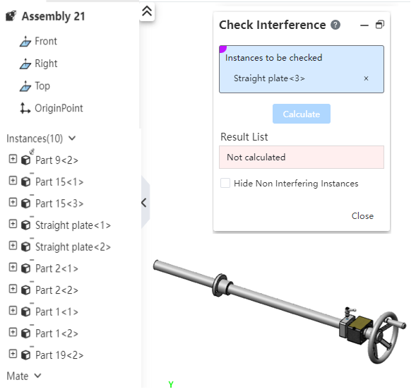
# Interference check supports select all/select box
In the "Instances to be checked" pickup box of the interference check command, you can click the document name at the top of the feature panel to select the entire document. At this time, the calculation range is all parts instances in the current document. At the same time, it supports the box selection to select the component instance to be checked.
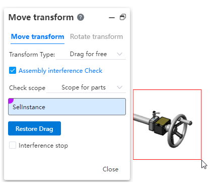
Dynamic interference function of moving parts command, "Select parts" pick up frame support frame to select the parts to be checked.
# Sheet Metal
Added the closing Angle function. When the two bent edges are drawn, the open area of the adjacent bent edges can be closed or the docking mode of the two bent edges can be modified.
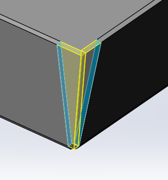
Note:
① The selected entity must be sheet metal.
② The area to be closed is the open area between the opposite sides of the two edge flanges on the same corner.
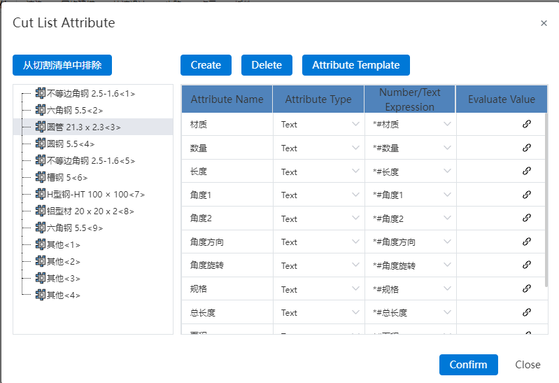
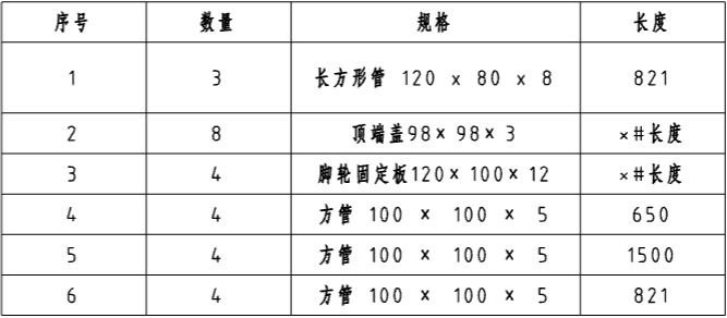
# The weldment cut list is enhanced
1)Support for reading physical attributes
The corner brace or other entity can be correctly read in the cut list table of the engineering drawing after adding properties.
2)Exclude from the cut list
Add the "Exclude from the Cut list" function to the cut list so that certain cut list items (entities) are not shown in the cut list of drawings.
# BOM
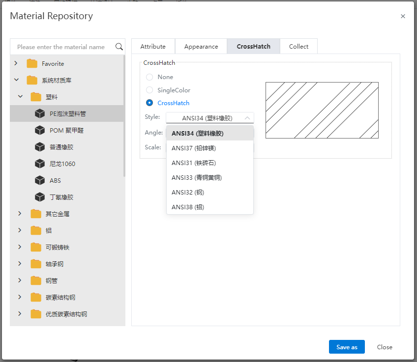
# Custom material library
Support to create custom material library, you can create custom material and set material properties and appearance.
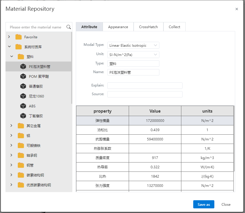
The basic process of creating custom materials:
① Right-click any library, select the "Create Library" option, enter the name to create a custom library, while creating a "category" by default.
② Right click on the newly created custom category, select "Create Material" and enter the name to create a custom material.
③ You can also generate a new material by "copy-paste" method, which supports copying a single material or copying an entire category.
Note:
- Materials must be stored according to the "library - category - material" hierarchy.
- Custom materials cannot be created in the system's preset libraries or categories.
- The parameters of custom materials can be modified, and the parameters of preset materials are not allowed to be modified.
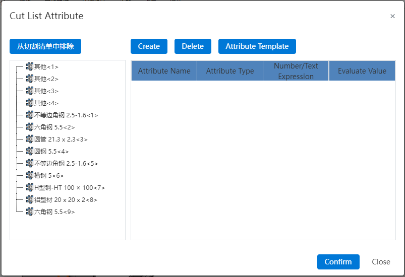
# Enhance custom property Settings
1)Added "Type" option
Add the "Type" property to the default property template, the initial value is empty by default, you can select from the drop-down box: homemade parts, standard parts, purchased parts, outsourced parts four types.
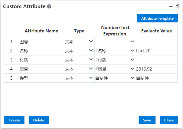
2)Add two columns "Numeric/literal representation" and "Evaluated Value"
- Numeric/literal representation: Used to select or enter text/associated properties.
- Evaluated value: Displays the specific value of the content according to what is in the "Numeric/literal representation". If the text "HCG01-02004" is entered, the text "HCG01-02004" is displayed here. If you enter or select the associated attribute "# name", then the attribute value of the associated attribute "Baseboard" is displayed here.
Note:
① The "numerical/text expression" content can be selected and inputted by the "type", where if the "type" is selected as "number", only numerical-type text can be inputted here.
② The "evaluated value" content is controlled by the "numerical/text expression" and cannot be modified in this column.
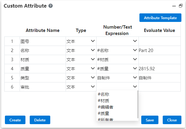
3)The drop-down button includes all available associated properties
Click the drop-down button in the "Numeric/Literal representation" column of the "Text" type property, and the drop-down box content that pops up adds "All available associated properties" to the original version.
# Node branch statistics
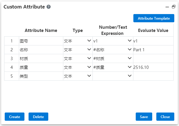
When creating a node or branch, add the "Edit Custom Properties" option to save a set of custom properties for each node or branch.

1)Create custom properties for nodes or branches
- Edit Custom Properties is unselected by default: Click OK to finish creating a node/branch. The content of the custom properties of the node/branch is the same as that of the current custom properties of the document.
- Manually check "Edit custom properties" : click to confirm the pop-up "Custom properties" dialog box, the content is the same as the current custom properties of the document by default. After modification, click Save to complete the creation of the node/branch. The content of the custom properties of the new node/branch is the same as the modified content. The custom property content of the current branch of the document is not affected.
2)Modify the node/branch custom properties
Enter the node/branch to be modified, click Custom property in BOM module, open the custom property dialog box, display the custom property of the corresponding node/branch, which can be modified and saved;
Note: When modifying the BOM property of the node document, the material item cannot pop up the context menu for right-clicking materials, that is, it is not possible to modify the document material actually, but manual input text-type material attribute values are supported.
# Data conversion
# Enrich the data conversion format
Added the supported types of data import, including RVT, 3DXML, SAT, and Inventor files.
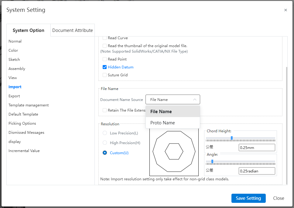
# Select/define the import data name
A file in a format such as CATIA, where the part name recorded in the file may not be the same as the file name. When importing such files in CC, it is supported to read the part name information recorded in the file, and you can choose to use "file name" or "Part name recorded in the file" as the name of the part document after import.

Note:
- You can also set whether to keep the file extension when using the file name as the document name source.
- For files in formats such as STEP that contain both assembly and parts in one file, this option only applies to the name of the top-level assembly, and other parts use the part name recorded in the file.
# Read Hidden parts
In the new version, it is supported to set whether to read hidden parts in the assembly file.
- Check:Do not read hidden parts in assembly files.
- Unchecked (Default) :Read the hidden parts in the assembly file, and the originally hidden parts are still hidden.
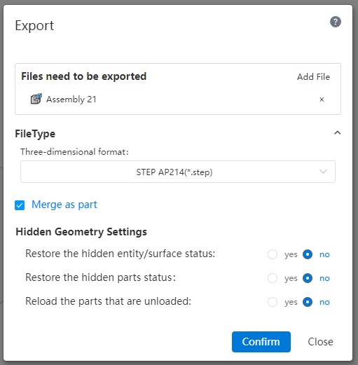
# The assembly is exported as part
Assembly files support merging as part exports when exported to other formats; Parts/surfaces in the assembly remain in the position in the assembly before export, and all are tiled in a part (does not automatically merge the entity); The origin of the part overlaps with the origin of the assembly.