# Plane
Automatically identify the type of datum to be created according to the different elements picked up. You can also select the type before picking up the elements. The datum created can be used to draw a sketch, generate a profile view of the model, and so on. Datum types include offset, plane-point, line Angle, point normal, three-point, plane-angle, and midplane,tangent,two line.
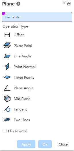
Click the toolbar to  open the Datum Command Dialog, whose command interface is shown in the following figure.
# Type
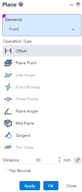
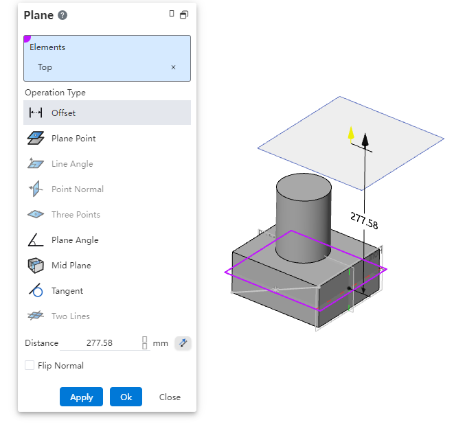
- Offset: A parallel offset of a fixed distance relative to a selected plane.
Note:
Planes can be planes, planes, or solid faces.
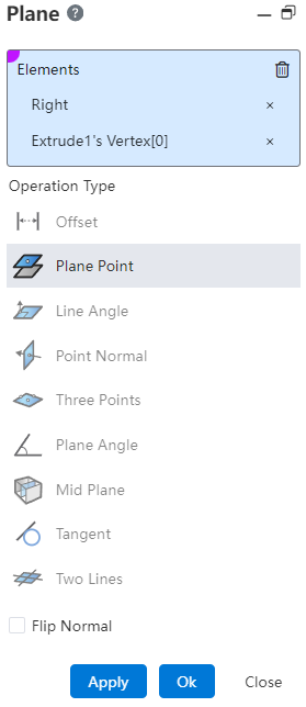
- Planar Point: Creates a datum plane based on a plane and a specified point.
Note:
A point can be a sketch point, origin, or solid vertex.
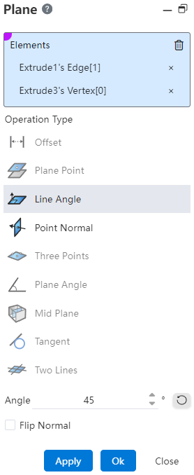
- Line Angle: Creates planes with different angles based on a line and a specified point.
Note:
Points and lines are not collinear; Lines can be sketch lines or solid edges, and selecting curves is not supported.
- Point normal: Based on a line or a line and a specified point, create a mutually perpendicular datum.
Note:
When selecting only one line, you can control where the datum is generated by specifying a percentage on the curve.
Three Points: Select three points in space that are not collinear to determine a datum.
Plane Angle: Select a plane to rotate around the axis by a certain angle to create a plane.
Note:
Axes can be sketch lines or solid edges, and selecting curves is not supported.
Normal reversal: The default is not checked, and the normal of the datum plane created after checking is opposite to the normal of the selected surface.
- Middle plane: Select two planes and generate the middle plane of the two planes as the reference plane.
Note:
The surface can be the plane and datum of the solid surface
Tangential: Select a surface and a point/line/surface to generate a datum that is tangent to the surface..
Two lines: Select two lines to create a datum through the intersection of the lines or the specified point.
Note:
【Lines can choose two lines that intersect or do not intersect, if you choose a line that does not intersect, you must pick up a designated passing point】
# Mode of Operation
- Select a plane, the activation type is offset, planar point, plane angle, at this time the irrelevant type will be dimmed and not selectable, the default activation display is offset.
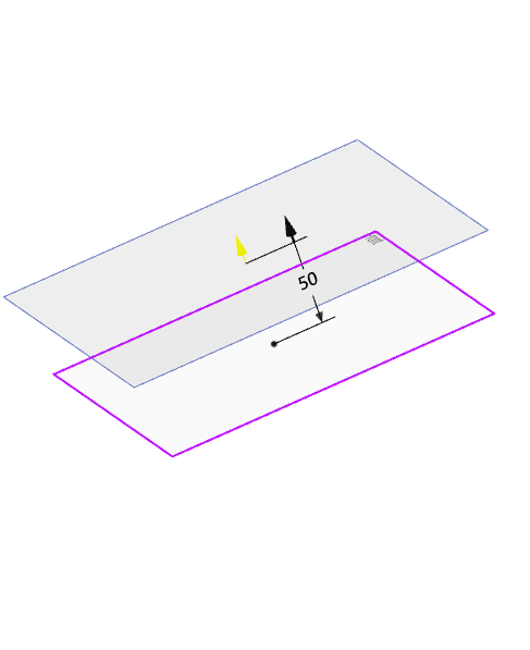
Offset
Create an offset plane based on the input offset distance or drag the black arrow in the viewport, which represents the normal direction of the plane. The effect is shown in the following figure:
Plane Point
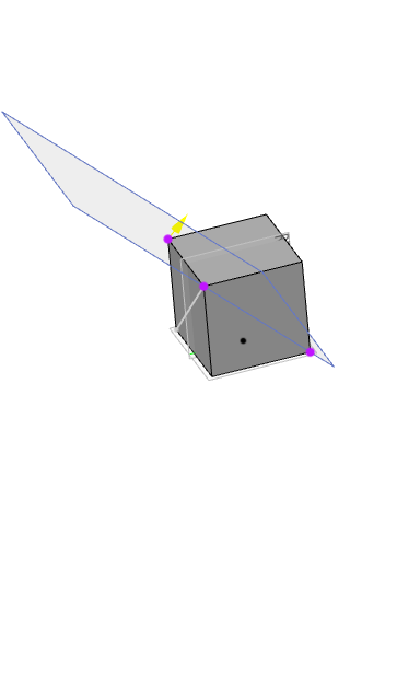
The element pick box selects a point on which a plane is created parallel to the selected plane, and the yellow arrow represents the normal direction of the plane. The effect is shown in the following figure:
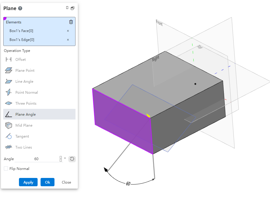
Plane Angle
Create a plane based on the angle of rotation entered or by dragging the arrows in the viewport, with the yellow arrows representing the normals of the plane. The effect is shown in the following figure:
- Select a line, activation type Wired Angle, point normal, plane Angle, tangent, two straight lines, at this time the irrelevant type will be dimmed and cannot be selected, the default activation is displayed as line Angle.
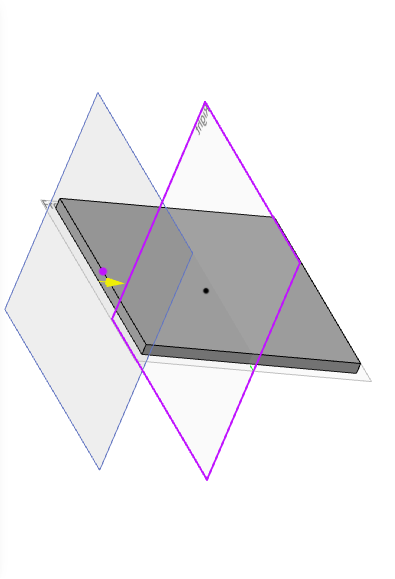
Line angle
The element picks a point outside the line and generates a plane by changing the angle value, with a yellow arrow representing the normal direction of the plane. The effect is shown in the following figure:
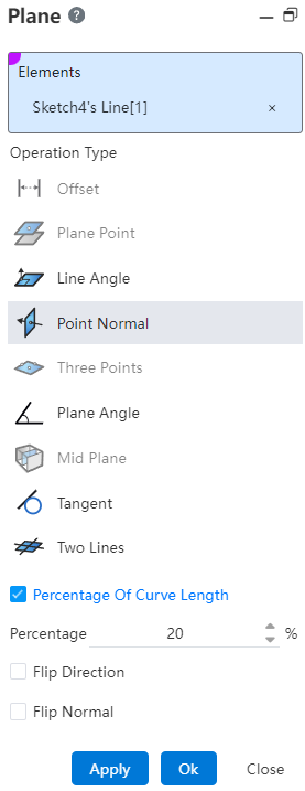
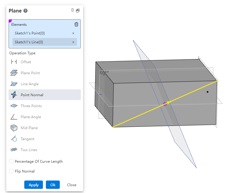
Point Normal
- Check the curve length percentage and modify the value to generate the datum plane perpendicular to the curve in the corresponding percentage position, the yellow arrow represents the normal direction of the datum plane. The effect is shown in the image below:

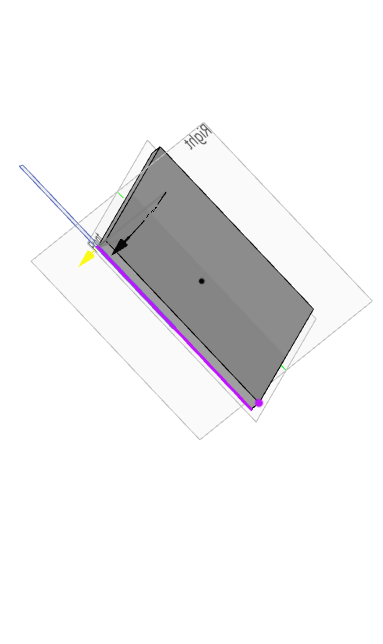
- Select a point on the straight line.Generate a reference plane perpendicular to the selected line at that point.Yellow arrows denote the normal direction of the newly created reference plane.The result is illustrated in the figure below:
Two Lines
Select another straight line and generate the reference plane containing the surface formed by the two intersecting lines. Yellow arrows indicate the normal direction of the reference plane, as shown in the figure below:
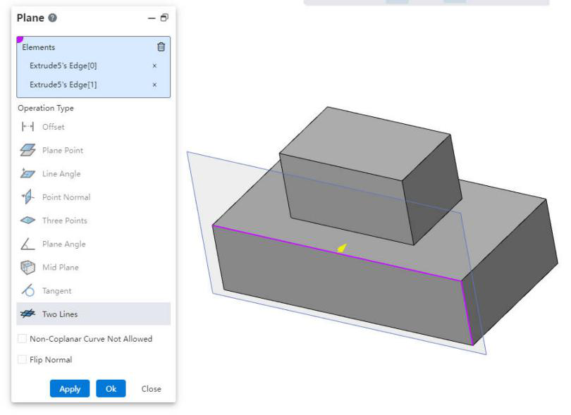
Note:
【To restrict the selection of straight lines, you can enable the option 'Do Not Allow Non-Coplanar Curves', ensuring that only lines in the same plane are selectable.】
- Select a point, the activation type has plane point, line Angle, point normal, three points, at this time the irrelevant type will be dimmed and cannot be selected, the default activation is displayed as line Angle.
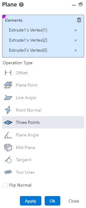
- Three Points
Click on the three points and pick up the other two points to establish the datum. The effect is shown below:
- Select two faces, the activation type has a middle face, at this time the irrelevant type will be dimmed and not selectable; The relation between the relative position of the picked plane and the generated midface is shown in the following figure:
| Pick up the relative position relation of the plane | Graphical representation |
|---|---|
| Parallel (Choose the left and right sides of the model) |  |
| Coincident (Pick the top of both models, located on the same plane) |  |
| Intersecting (Pick the top and bottom of the model) |  |
- Select the surface, the activation type is tangent, and the irrelevant type will be dimmed and unselectable at this time; The default activation is displayed as tangent, and the tangent situation is as follows:
| Tangential datum case | Graphical representation |
|---|---|
| Common surface(Choose a normal surface and a point, the point can not be on the surface) | 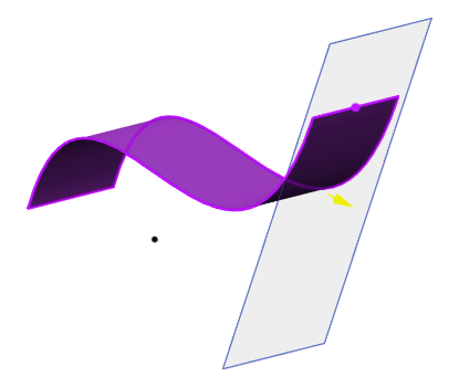 |
| Cylinders and lines(Select the cylinder and a line) | 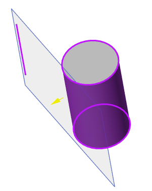 |
| Cones/cylinders and points(Select a cone/cylinder and a point) | 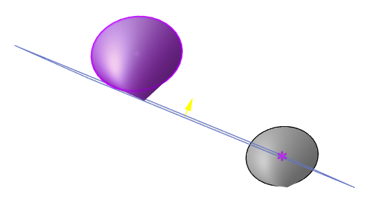 |
| Two cylinders/cones(Select two cones/cylinders, do not support mixing selection, you can control the tangential direction by checking the reverse) | 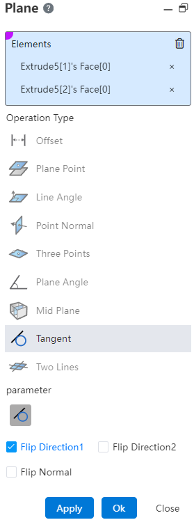 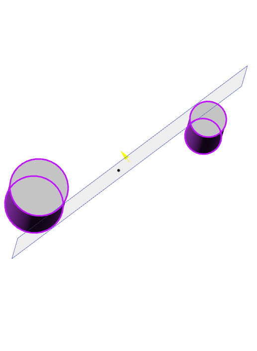 |
# Quick Creation
Create Method 1:
1) In a part or assembly, hold down the Ctrl key while your mouse left-clicks on any datum in the viewport.
2) The Create base level dialog box is displayed, and the base level is automatically filled.
3) Modify the parameters in the dialog box as needed.
4) Click OK or Apply to finish creating.
Create Method 2:
1) In a part or assembly, hold down the Ctrl key while left-clicking the mouse over the viewport to drag any datum.
2) The Create datum dialog box pops up, and the datum preview moves with the mouse.
3) Drag to the desired position and release the left mouse button.
4) Modify parameters in the dialog box as needed.
5) Click OK or Apply to finish creating.
Note: In Method 2, you can release the Ctrl key after the datum plane dialog box pops up.