# Variable
Use this command to create variables or manage variables. Variables facilitate the application of expressions and assignments in CrownCAD modeling .

Click  to enter the variable management command, and its interface is shown as follows.
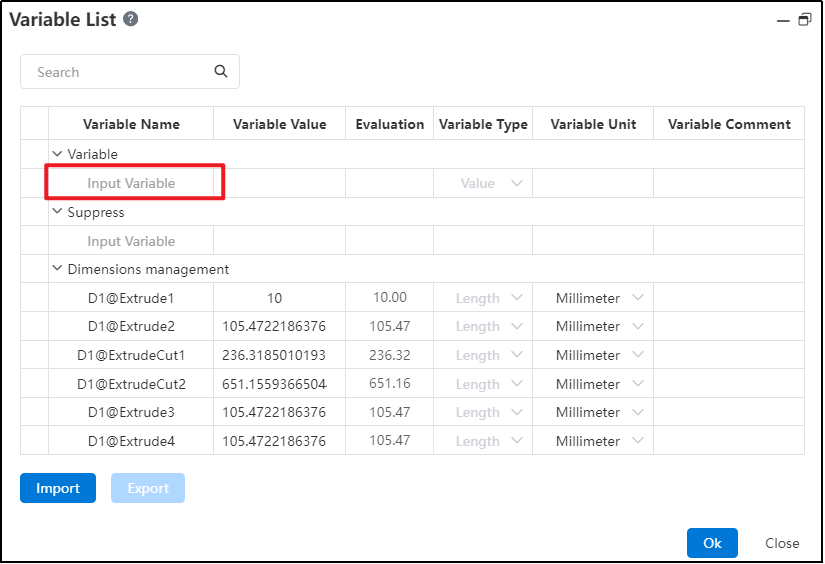
# Create a Variable
Click Enter variable, set variable name, value and other parameters to complete the creation.
The descriptions of each control are as follows:
Variable name: User fills in the name of the custom variable;
Variable value: The user fills in the variable value, supports the input of the formula;
Valuation: the valuation of the variable value, with three decimal places;
Variable type: There are 3 data types, namely "length", "angle", "value";
Variable unit: There are 7 kinds, namely " mm " , " cm " , " meter " , "degree", "radian" ;
Variable remarks: user-defined remarks.
# Modify/Delete variables
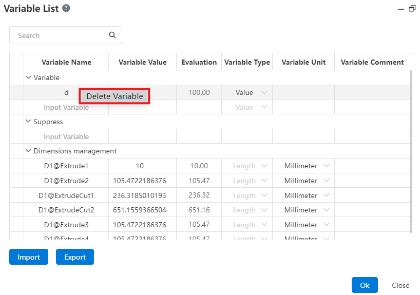
Existing variables can be modified or deleted in the interface.
Click the variable parameter that you want to modify and enter the content to modify the variable.
Click the blank space in front of the variable you want to delete, and right-click to delete the variable, that is, you are finished deleting the variable.
# Import/Export
Can choose to import the local variable table or export the variables in CrownCAD to the local in table form.
- Import
- Click Import to pop up the import panel . Users can download a variable template , organize variables according to the template style , and drag the table into the pick box.
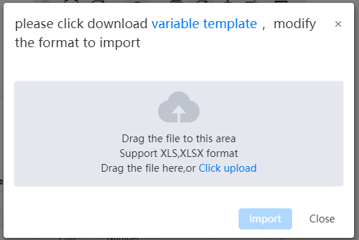
Click Import in the Import panel to determine whether the variables in the table are supported.
- If it is not supported, the corresponding prompt is given, and you can modify it according to the prompt and upload it again.
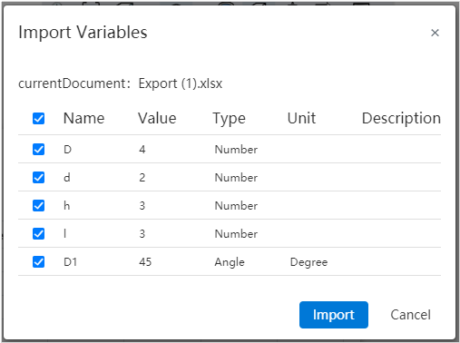
- If yes, the variables in the table are displayed on the page. You can select the variables to import.
- Export
- Click Export to export all the variables in the document to the table.
# Operators, Functions, and Constants
In the input box that supports equations, you can calculate the value to be entered directly by entering formulas such as operators and functions. The supported operators, common functions, and constants are shown in the following table:
| Types | Symbols | Comments |
| Operators | + | Add |
| - | Subtraction | |
| * | Multiplication | |
| / | Division | |
| ^ | Exponentiation | |
| Functions | sin | Sine |
| sinh | Hyperbolic sinh | |
| asinh | Inverse hyperbolic cosine | |
| sech | Exponential function | |
| cos | Cosine | |
| cosh | Hyperbolic cosine | |
| acosh | Inverse hyperbolic cosine | |
| tan | Tangent | |
| tanh | Hyperbolic tangent | |
| sec | Secant | |
| csc | Cosecant | |
| csch | Hyperbolic cosecant | |
| cot | Cotangent | |
| coth | Hyperbolic cotangent | |
| acoth | Inverse hyperbolic cotangent | |
| asin | Arcsine | |
| acos | Arc cosine | |
| atan | Anticut | |
| asec | Antisecant | |
| asech | Inverse hyperbolic secant | |
| acsc | Anticosecant | |
| acsch | Inverse hyperbolic cosecant | |
| acot | Arc cotangent | |
| abs | Absolute value | |
| exp | Index | |
| log10 | Logarithm | |
| sqr | Square root | |
| if | Conditional function | |
| Constants | pi | PI |
The variable supports the use of the IF function, the syntax is IF (condition, result 1, result 2), the condition is an expression, result 1 is the result returned if the condition is true, result 2 is the result returned if the condition is false
In the IF function, the condition can be a logical expression or a combination of multiple expressions, and operators such as AND and or can be used to build the condition, or it can be nested.
The IF function can control the size by conditions, such as A=IF (' D1@ sketch 1 '> 30,10,8) means that if the value of D1@ sketch 1 is greater than 30, the A variable takes 10 otherwise 8.
In the assembly, the IF function can be used to control the features, such as the number or distance of the array by the size of the part.
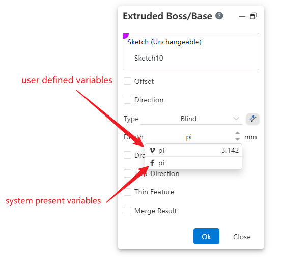
When you type "P" or "PI" (case insensitive) into the input box that supports the equation, the "pi" option is displayed. Select this to fill the function pi into the cursor of the input box.
Supports creating a custom variable named pi without conflicting with the system preset constant pi. In the input field, single quotes are displayed on both sides of the variable pi, whereas the function pi has no single quotes, as shown below:
# Size management
# Sketch Size Number
Sketch Dimension Numbering is used for unified dimension management. It is displayed when creating sketch dimensions, editing sketch dimensions, and viewing dimension properties..

When creating sketch dimensions in sketch, add a number for each dimension to display when creating sketch dimensions, editing sketch dimensions, and viewing size properties.
# Feature Size Number
Record the dimensions of all features in the parts, assembly.

Double click on the feature in the feature list to display the feature size in the viewport, click on the feature size value to modify the size but not the number, and double click to modify the size and number.
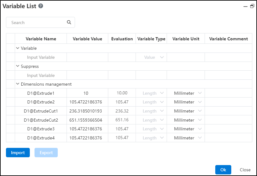
# Dimensions Management
Display and manage dimensions uniformly in variable management.
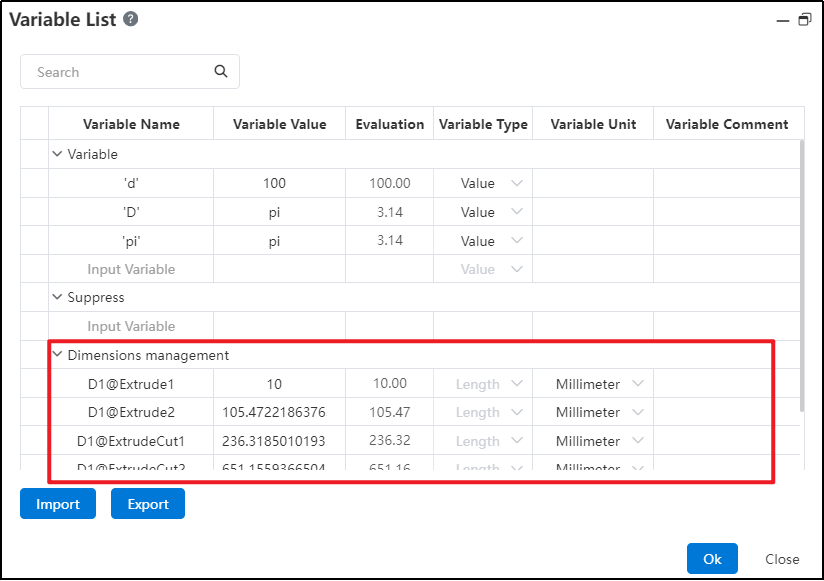
Size name: can be edited and changed, can only modify the number can not change the suffix, and keep consistent with the characteristics.
Values: Can be edited and modified. Expressions containing variables are displayed, and if they are constant expressions, only the final values are displayed.
Valuation: Displays the calculated result according to the numerical value, which cannot be edited.
Type: Display type according to size, such as distance as length, rotation Angle, array number as value, percentage as value, cannot be edited
Unit: Can be changed to the supported unit of the current type
In size management, the dimensions or items that cannot be edited are set to gray.
Edit the sketch or feature to modify the size value in the list automatically updated, vice versa in the list to modify the value can also drive the feature update.
Document dimensions cannot be deleted. Dimensions created in assembly can be deleted. Editing related functions are described below.
# Edit Dimensions In Assembly
In the dimensions list of the assembly document, you can associate parts, variables in the assembly, or dimensions with existing dimensions, driven by the same data.
Open the variable management in the assembly, and display the size of the fit, feature and sketch in the current document in the size list.
Click the name box in the blank column, you can pick up a size in the viewport, and automatically fill the number of the size into the variable name.
After confirming the name, press enter to focus on the value input box, the value supports the input item:
Select assembly variables and functions from the drop-down list
Enter the value, calculation formula
The dimension value of any part or assembly in the current document cannot be the same as the dimension value in the name. It can be entered or picked up, and the input rules are consistent with the name; Pick can be picked up in the viewport, or click the size name in the size list
Dimensions also support the calculation formula, such as' D1@ distance 1 '+' D1@ distance 1@ part 1 '
Automatically calculate and fill estimates based on the picked value type.
The type and unit are automatically filled according to the picked variable name size, the type can be modified to a number but cannot switch the Angle or length, such as the name is the length size, the value is the Angle size, the created variable is still the length, only the value of the Angle size is taken.
After completing the size creation and clicking OK, the size picked up at the name will be automatically driven by the value set in the size management.
When the dimension of a part refers to the value or variable of another part, that dimension is an external reference status in the document.
Automatically create a new line of blank table after adding the dimensions; The created dimension right button shows the delete function, click to delete the dimension.
Example Scenario 1:Part size is set as variable in assembly
There is dimension [D1@ sketch 1=20mm] in part P1, the size list is opened in assembly, and the name picks up the size
Enter 30 in the value, OK, the size becomes 30 in the viewport, and is displayed as variable style:
In the assembly, the value can be modified by editing the size or in the size list, which automatically becomes a constant when the size is deleted from the size list
In parts, editing the dimension shows as external reference cannot be edited; The dimensions are removed and then go back to the assembly to open variable management, indicating that the name of the variable is missing
Delete the association effect, D1@stretch 1 in the part completes the above operation, when there is a D1@stretch 1 in the part after deleting the stretch, creating the stretch, renaming the feature, the size is automatically used in the assembly
Suppression of features, sketches and rollback in the part do not affect the variables in the assembly
In the above piece, change the input value to the variable A=25 already in the assembly, and the variable created at this time is:

Example Scenario 2:The part variable is referenced by another part
Part 1 has variable A=25, dimension D1=A, and part 2 has dimension D2=15mm
Open the size list in assembly, pick up the name D2, pick up the value D1, create a variable as:

The dimensions in part 2 are now associated with D1 in part 1, and D2 will always hold the same value even if D1 is changed to a constant
After modifying the variable in part 1, you must first open the assembly document for part 2 to update automatically, and directly open part 2 does not update
Suppressing, rolling back and other operations in part 1 do not affect variables in assembly
Delete the size in the part, and then return to the assembly to open the variable management, prompting the corresponding name or value is lost, can be re-edited
Delete this item from the size list of assembly, and the value of D2 size in Part 2 becomes a constant value
Edit D2 in Part 2 prompt that external reference cannot edit, deleting this dimension has no effect on other documents
In the above condition, when the variables are created interchangeably D1 and D2, then D1 in Part 1 no longer refers to the variables in the original document and is controlled by D2 in Part 2
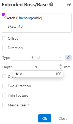
# Edit Dimensions In Parts
In the dimension list of the part document, the dimension of the part can be associated with an existing dimension or variable, driven by the same data.
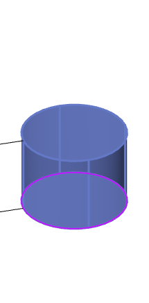
Example Scenario 1:Feature size modification
There are dimensions [D1@ sketch 1=20mm] in part P1, and the dimension list is opened in part P1
Enter 30 in the value of the item, OK, the size in the viewport becomes 30, and the feature is automatically updated
This size is still a constant, and it will be updated here when the value is modified by editing the feature
In the above, change the input value to the variable A=25 that is already in the part, and the dimension becomes the variable style
Example Scenario 2:Feature size association
Among the parts are: D1@ stretch boss 1=25, D1@ sketch =A, create stretch cut 1=10mm
Open the list of dimensions and in the value of the D2 item set to: D1@stretch boss 1-10
The valuation is 15, click OK and then the stretch cut will update automatically
After modifying the value of stretch boss 1, stretch excise 1 is also automatically updated
Edit stretch cut 1 and the depth value is displayed as in the list
After deleting stretch 1 (assuming it is not associated with deleting stretch excision), go back to the size list and indicate that the value is missing and you can edit the pick again
Delete and then undo the rollback size list will automatically return to normal state
# Suppress
In a part or assembly document, the suppression of features can be controlled by equations.
In the part document, select the Feature Suppression option in Variable Management.
Feature: You can enter the feature name or pick up the feature in the part document.
The reference plane, origin, and size of the document cannot be picked up. The center of mass, sketch, and feature can all be picked up. When the feature is in the rollback state, it cannot be picked up
It can be picked up in the viewport or feature list, only the existing feature can be input, such as stretch 1, and the feature will be automatically associated after input
The feature is renamed and automatically updated in the table; Features are deleted, automatically deleted from the table; The table is not affected when the feature is rolled back
Auto focus to the next cell after picking up the feature
- Value: Select add equation for this feature, autofocus to note after input
Supported types are consistent with variables and dimensions
Add two options to variables: Suppress and unsuppress
Valuation: Returns the status or value of the current feature. Cannot be edited here, only displayed. Suppress or unsuppress only takes effect on features, not numerical values.
Type, unit gray unavailable.
Note: Select the field, press enter to complete the creation of the current feature equation and automatically focus to the next line.
Function effect:
The suppression effect is consistent with the feature right-click suppression function, the parent feature is suppressed in the equation and the child feature follows the suppression
By the same token, no matter what the state is before picking up the feature, the state of de-inhibition is maintained after creating the equation
When the feature changes from suppressed state to uninhibited state, the feature and its parent feature automatically become uninhibited state, and the child feature is still suppressed state, and you can cancel the inhibition by right-clicking
- After a feature is suppressed or uninhibited in the list, the suppression-related function buttons are no longer displayed when the feature is right-clicked
- The feature creates an equation, remains in the current state after deleting the equation, and restores the suppressor function button when right-clicking
- Feature Suppression is added to or removed from the list. After a feature is deleted, the list displays a message indicating that the feature name is lost. You can pick up the feature again.
Example:
Base level 1= suppressed: Base level 1 is always suppressed
Stretch excision 1=IF (' D1@ stretch boss 1 '< 30, inhibit, uninhibit) : When the depth of stretch boss 1 is less than 30mm, inhibit stretch excision 1, uninhibit when greater than or equal to 30. Stretch excise 1 will follow the depth of stretch boss 1 to determine the suppression state.