# Customize the Structural Member Outline
Users can draw their own sketches and save them as weldment structure Outlines for use when generating weldment structure members.
Custom contours
(1) Users can draw a 2D sketch on any plane and save it as a structure outline.
(2) Sketch requirements:
- The sketch must include a closed sketch area composed of non-guides, but there can be no more than one sketch area;
Sketch Styles Single enclosed area Single enclosed area with internal outline Multiple enclosed areas Unenclosed areas Legend 


Whether or not Support is is no no - Secondary guides can be included in the sketch, drawing points
- The sketch origin will default as the penetration point in the component that coincides with the path.
- Sketch dimensions can be defined by variables or constants.
Save outline
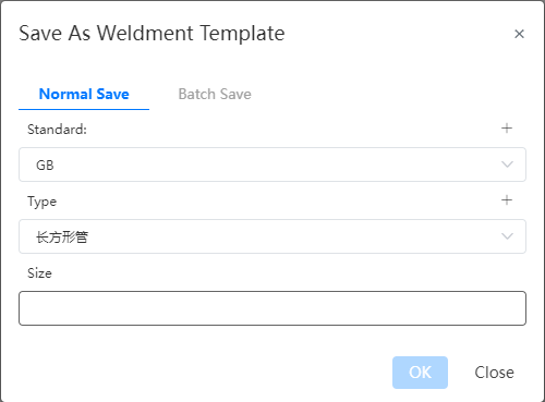
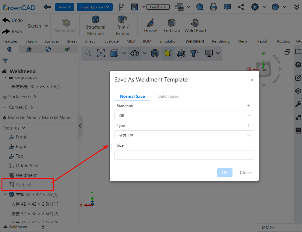
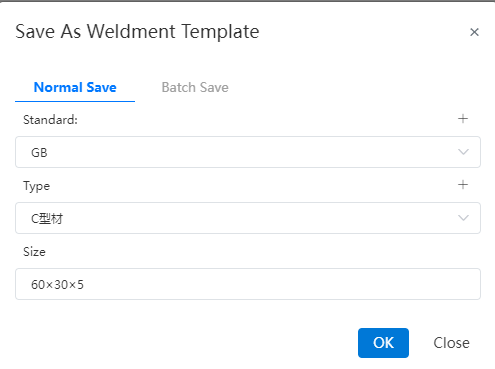
(1) Click the arrow to the right of the Save button and select "Save as frame Outline" to bring up the "Save as frame Outline" dialog box to save the structure outline

- The sketch you want to save should be checked in the feature panel before saving
- If there is only one sketch in the document, you do not need to select, and the system automatically saves the only sketch
(2) Support ordinary save and batch save two kinds of saving methods
- Ordinary save: save the outline of a single size, the size of the outline sketch is the size of the sketch in the current part;
- Batch save: upload a table that conforms to the rules and generate multiple Outlines of different sizes in batches. The size of each outline is controlled by the variables in the table and the corresponding size variable in the sketch;
- Save the table rules in batches:
- The first is the header of the table, starting with the second row and each row representing a specification;
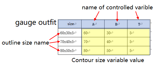
- The first list is headed by "size" and contains the "size" name of each outline. Starting from the second column, the name of the table header is consistent with the name of the variable controlled by the column data, and the content is the value of the corresponding variable in the outline of each size. To control several variables, add several columns of data. Special characters that are not supported as names are not allowed in this column;
- Table head, contour size name, variable name, variable value of each contour size is not allowed to exist blank cells;
- The variable name must correspond to the variable name created in the sketch for it to take effect correctly. Variables that exist in the table but are not in the sketch are ignored and not used. Variables that exist in the sketch but are not in the table are taken as the values of the variables in the sketch.
(3) Example of saving a custom outline:
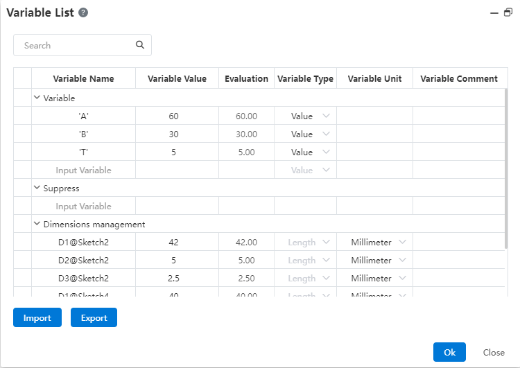
- Create A new blank part document and set variables A=60,B=30,T=5
- Draw the following sketch on the front view datum, annotated using the variables in step 1

- Save separately: Select standard GB, type L-shaped steel, size 60 x 30 x 5. After saving: Add 1 outline to standard GB, type L-shaped steel, size 60 x 30 x 5, size as in the sketch.

Note:The standard and type can be selected as existing, or you can click the "+" sign in the upper right corner to create it. The created data will be automatically recorded in the library and can be directly invoked later.


Batch saving: Select standard GB, type L-shaped steel, upload thetable as shown below.
Size A B T 60×30×5 60 30 5 70×40×5 70 40 5 80×50×5 80 50 5 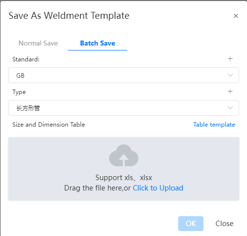
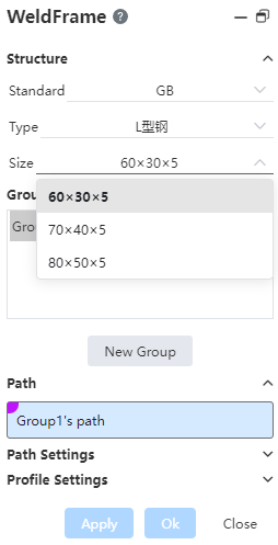
After saving: standard 【GB】, type 【L-shaped steel】 there are 3 Outlines, the size is "60×30×5,70×40×5,80×50×5", the specific size of each sketch is controlled by the value of each size corresponding to A, B, T in the table.
Manage the outline
Select "Weldment Profile" in System Settings - System Options - Template Management to manage.
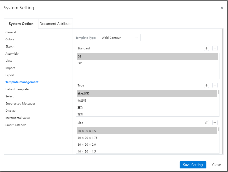
Select the outline to be edited, click
 the edit command, enter the sketch editing state as shown in the following figure, you can edit the sketch corresponding to the size.
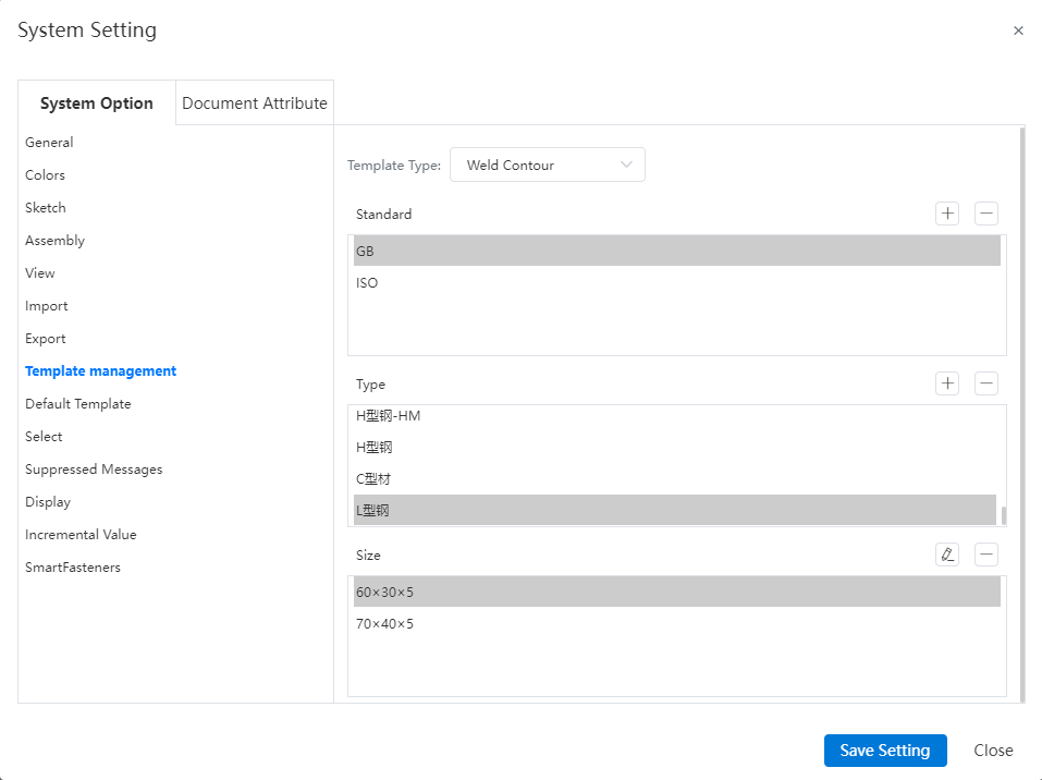
Note:Editing the outline needs to be carried out in the project management state. When the system is in any open document state, editing the outline will prompt "Please exit the current document first".
- After modification, click Save to save the current modification. It is not possible to exit the sketch by Exit Sketch button.
- Click the Back button to exit the workspace and return to the home page. If the changes are not saved before returning, a confirmation dialog box "Save structure outline or not" will pop up:

- Click 【OK】 to save and return to the home page, click 【Cancel】 to return to the home page without saving the changes.