# Cut List Attribute
The number, size, length, total length, material, etc. of the weldment entity are recorded in the Cut list properties and support the user can set other custom properties for the weldment entity.
- Right-click "Cut List item" in the feature panel and click properties. View and edit the cut list properties in the pop-up "Cut List Properties" dialog box.

- The left side shows the cut list item in the current document, and the right side shows the properties and property values of the selected cut list item.
- 【Excluded from Cut List】:Excluded cut list items are not displayed in the weldment cut list table of the engineering drawing.
- 【New】:Click to pop up the "Add properties" dialog box, you can reuse the "Add properties" dialog box of "Custom properties"

- 【Delete】:Select any property, click to delete the property
- 【Attribute Template】:Click to switch "Cut list attribute template"

- For the modification and creation of the cutting list property template,see Template Management - Cutting List Property Template
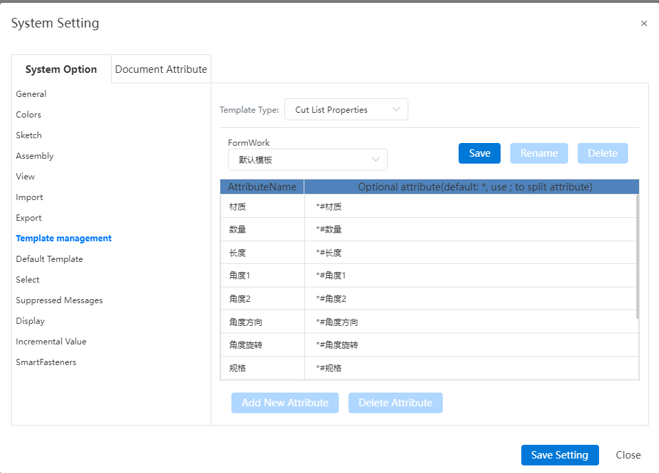
- Cut List linkage properties: Quantity, Specification, Length, total length, Material, Quality, Angle 1, Angle 2, Angle Direction, Angle rotation.
- Quantity: The cut list item has several entities
- Specifications: Structure outline type and size, such as "square steel 20 x 20 x 2"
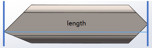
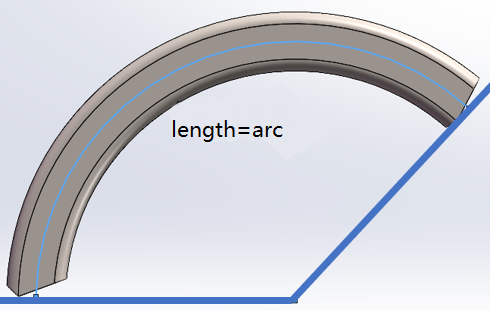
- Length: Profile length, showing the maximum distance between the sections on both sides of the profile in the direction of the path
- Total length: The sum of the lengths of profiles of the same specifications
- Material: solid material
- Quality: Physical quality
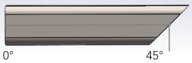
- Angle 1, Angle 2: The Angle between the two ends of the profile and the normal plane of the path. The attribute value is - when the end face is non-plane.
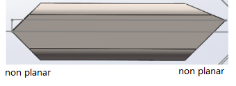
- Angle direction: The two end face direction types of profiles are "same, opposite, out of plane". There are non-plane end faces, or one side of the Angle is 0° when the property value is -.
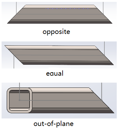
Angle rotation: When the direction type of the two end faces of the profile is "out of plane", the relative torsion Angle of the end faces is displayed. Let the normal direction of the two ends be A and B respectively, A and the path direction form a plane C, B and the path direction form a plane D, and the torsion Angle is the Angle of plane C and plane D.
The format of the linkage property is: "# quantity @ Cut list item 1", which represents the quantity value of cut list item 1.
Note:Quantity and material apply to all entities, other properties only apply to weldment entities generated by the "Structural member" command.
- The user can set other custom properties for the weldment entity.