# Welcome to CrownCAD 2026 R3
CrownCAD 2026 R3 incorporates extensive user feedback to fully meet your design requirements. In terms of usability, we are committed to enhancing user experience; in functionality, we continuously add essential commands that help you quickly complete product design and development tasks.
Main Enhancements:
| Sketch | Enhanced Spline command, displays real-time preview during drawing, and supports detailed curve shape adjustment via point control handles. |
| Added "Check Sketch" command to verify whether the sketch meets feature requirements. | |
| Enhanced Trim command, added options "Keep the trimmed elements as reference lines" and "Trim/Extend to Corner". | |
| 3D Sketch | Enhanced Constraints, supporting the "PointOnPlane" constraint. |
| Features | Enhanced Extruded Boss/Base command, supporting Up To Body. |
| Enhanced Plane command, added Curve-based Plane option. | |
| Hole Wizard added "DIN, JIS, ANSI Metric" standards. | |
| Enhanced Delete Face command, added Hole deletion function. | |
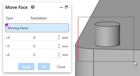
| Move Face supports box selection. | |
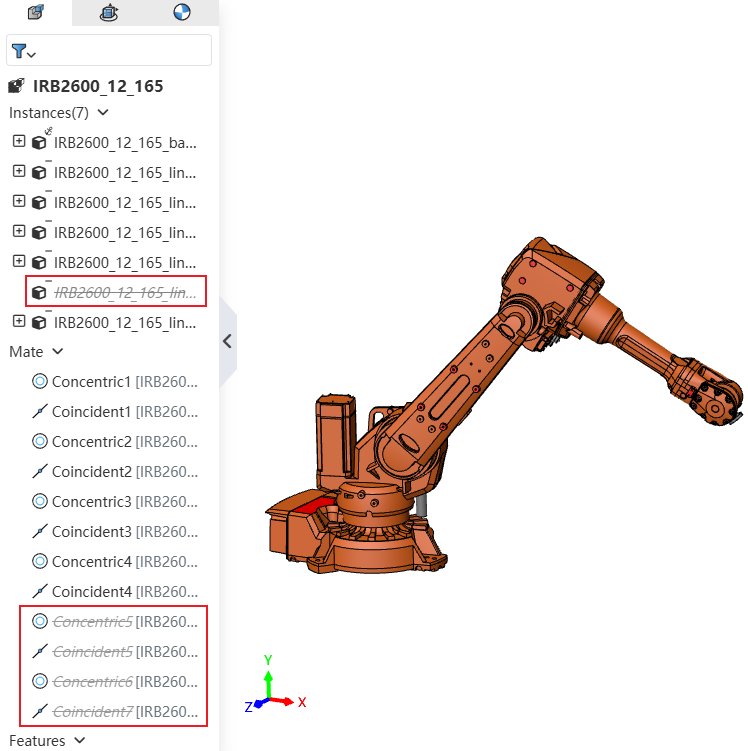
| Assembly | Unloading Instances automatically Suppresses related Mates. |
| Added Envelope function to set Reference Components. | |
| Deleting a Component retains Components with External Reference relationships. | |
| Drawings | Added Line Type Scaling function to uniformly control line type scaling ratios. |
| Enhanced Center Mark command, supporting various Slot dimension styles. | |
| Enhanced Note command, supporting display of associated properties. | |
| Enhanced Dimensions, supporting dimensioning Sheet Metal bend lines. | |
| Enhanced Ordinate Dimension, supporting batch modification of tolerances, arrows, etc. | |
| Evaluate | Added "Section Properties" command for measuring section-related parameters. |
| Sheet Metal | Enhanced Base Flange command, supporting Up to Vertex and Up to Surface. |
| Enhanced Edge Flange command, supporting Up to Vertex and Apply Release Slot Ratio. | |
| Added "Cut Vent" command for quickly modeling vents. | |
| Weldments | Structural Member added "ANSI, ANSI Inch, DIN, JIS" standards. |
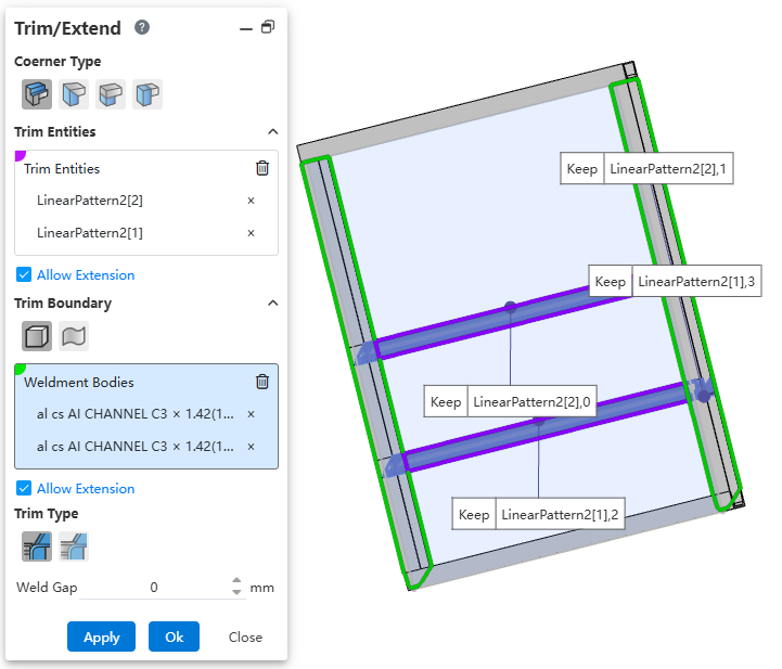
| Bodies generated by Pattern Mirror operations retain Weldment properties. | |
| Rendering | Enhanced Edit Appearance command, allowing appearance settings for Features. |
| Library | Optimized Material Repository and Standard Part Library details. |
| BOM | Assemblies support switching to set Custom Properties for Components. |
| Applications | Usability improvements for Project Documents and Scrollbars. |
# Sketch
# Spline
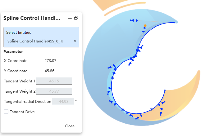
Each pass-through point on the Spline supports adjusting control handles to precisely control the curve shape.
Usage:
- Draw a Spline.
- Select the Spline. Control handles will appear on each pass-through point.
- Drag the control handles to modify the curve shape.
Note 1: Selecting the curve displays all control handles on it. Deselecting the curve hides unadjusted control handles.
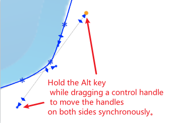
Note 2: Hold the Alt key while dragging a control handle to move the handles on both sides synchronously.
Curve Control Handle Description:

Circular Control Handle: Drag to adjust the handle's length and direction.
Triangular Control Handle: Drag to adjust the handle's length without changing direction.
Diamond-shaped Control Handle: Drag to adjust the handle's direction without changing length.
Note: Gray control handles indicate an inactive state (i.e., not manually adjusted). Blue control handles indicate an active state (i.e., manually adjusted).
Dialog Box Control Descriptions:
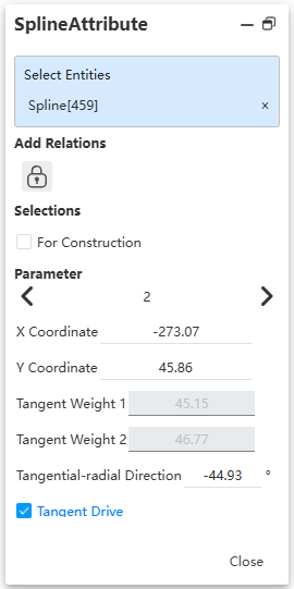
Add Constraint: Displays available constraints. Click to add the constraint to the selected element.
Reference Line: Controls whether the current element is set as a reference line.
Index: Displays which point on the curve corresponds to the current parameter. Click the left/right arrows to switch points.
Coordinates X, Y: Displays the coordinates of the current point.
Tangent Weight 1, 2: Displays the weights of the control handles on both sides of the current point.
Tangent Radial Direction: Displays the direction of the current point's control handle.
Tangent Drive: Check this option to manually set the control handle direction in the dialog box. Dragging other control handles will not affect this handle's direction. This option is automatically checked when dragging control handles in the viewport.
# Real-time Preview
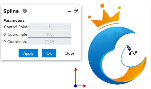
When drawing a Spline, a real-time curve preview is displayed based on the cursor position.
# Line
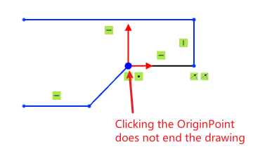
When drawing a Line, clicking the OriginPoint does not end the drawing; you can continue drawing lines.
# Trim
# Keep the trimmed elements as reference lines
Supports the "Keep the trimmed elements as reference lines" option.
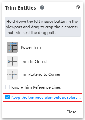
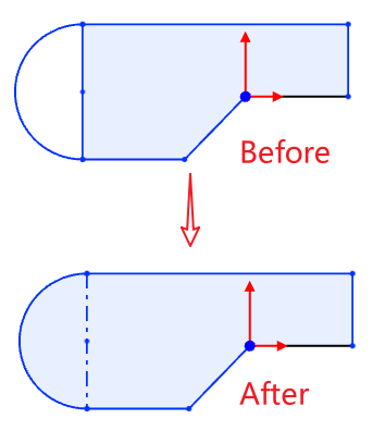
Check this option to trim without deleting the lines. Instead, the lines are converted to reference lines, which helps preserve sketch constraints.
# Trim/Extend to Corner
The "Trim/Extend to Corner" feature has been added. It supports one-click trimming to form a corner between two sketch lines, eliminating the need for multiple trim/extend operations. This makes sketch trimming more flexible and effectively improves modeling efficiency.
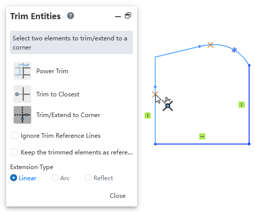
Usage:
Open the Trim command.
Select the "Trim/Extend to Corner" mode.
Click the curve in the viewport to create a corner. An X marker appears at the click location.
Select the other curve in the viewport to create a corner. Another X marker is displayed during preview.
Click to create the corner.
Note: When the selected curves have multiple intersections, the corner will be created at the intersection point closest to the X marker.
Extension Type Description:

Linear: Extends along the tangent direction of the Spline at the endpoint to be extended.
Arc: Extends along the selected Spline at the endpoint to be extended, maintaining curvature continuity.
Reflect: Extends the curve as a mirror image. The mirror plane is perpendicular to the curve plane, positioned at the location perpendicular to the curve tangent at the endpoint to be extended.
# Check Sketch Validity
The "Check Sketch" command has been added. Before creating or modifying sketches for features (e.g., Extrude, Revolve, etc.), run this function first to check whether the sketch meets modeling requirements or contains potential issues.
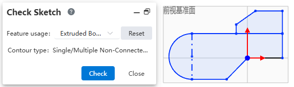
Usage:
Open the Check Sketch command.
In Feature usage, select the type of feature to which this sketch will be applied.
Click "Check". The system automatically checks whether the sketch can be applied to the selected feature.
If the check fails, a prompt message will appear explaining the cause of the error.
Click the OK button in the prompt message. The system automatically opens the "Repair Sketch" command to perform repairs.
Dialog Box Control Descriptions:
Feature usage: Select the type of feature to which this sketch will be applied.
Reset: Click to reset the Feature usage.
Contour type: Displays the contour type corresponding to the feature based on the selected feature.
Check: Click to check whether the sketch can be applied to the selected feature.
# PointOnPlane Constraint
A new PointOnPlane constraint has been added to 3D Sketches. It is used to constrain sketch lines, points, or curves to lie fully on a plane.
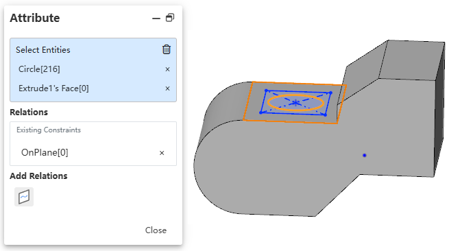
Usage:
In the 3D Sketch, select the sketch elements to constrain: 3D Sketch lines, curves, or arcs.
Hold the Ctrl key and select the plane to constrain to.
Click the PointOnPlane button in the Add Constraint section of the Property Dialog. The sketch elements are constrained to the plane.
# Parts and Features
# Extruded Boss/Base / Extruded Cut
The "Up To Body" option has been added for Extruded Boss/Base and Extruded Cut. This option is primarily used in scenarios where the feature needs to terminate on multiple faces of a single body.
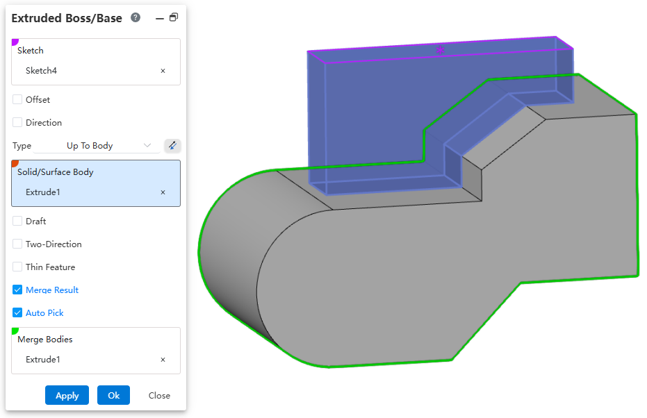
Usage:
Open the Extruded Boss/Base or Extruded Cut command.
Select the sketch.
Set the option to "Up To Body".
Select the target body/surface.
Click OK to complete the creation.
# Plane
A new Curve-based Plane option has been added, supporting the creation of a Plane using a curve that belongs to a single plane.
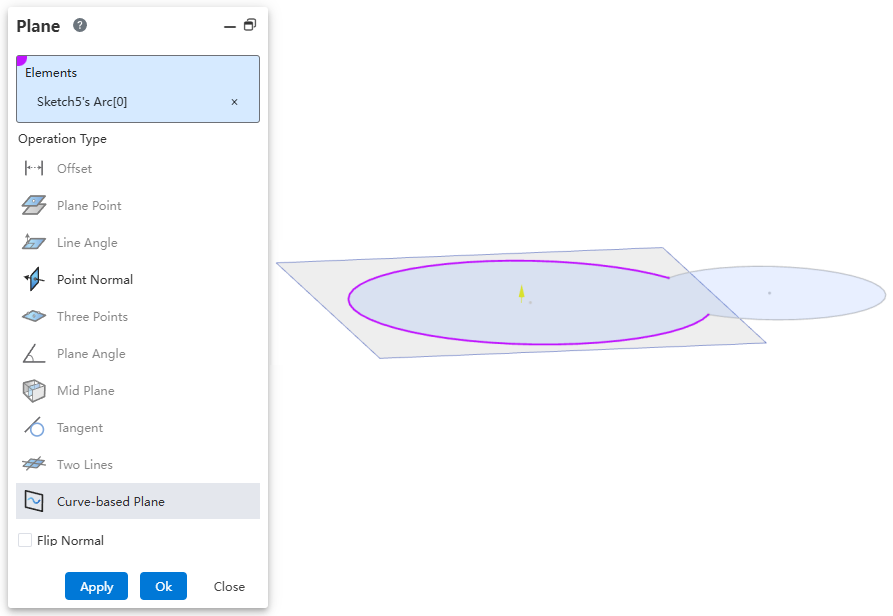
Usage:
Open the Plane command.
Select Curve-based Plane for the operation type.
Pick a curve belonging to a single plane. A Plane preview will be displayed.
Click OK to complete the creation.
# Hole Wizard
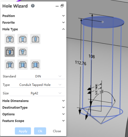
The Hole Wizard standards have been expanded, adding "DIN, JIS, ANSI Metric" standards.
# Pattern Mirror
The Pattern Mirror function supports recording the checkbox state of the Geometry Pattern option.
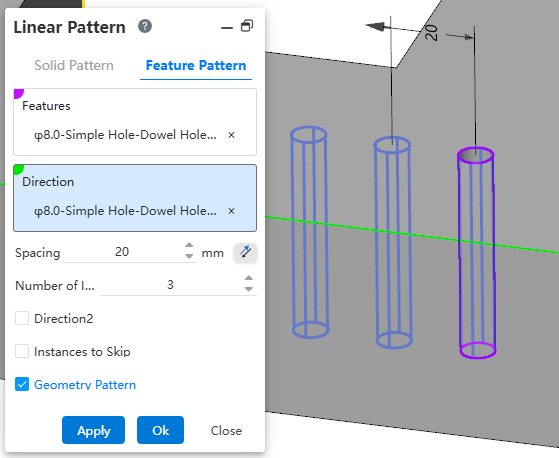
Checking Geometry Pattern can significantly improve feature creation speed, while unchecking Geometry Pattern enables Pattern Mirror in complex scenarios.
You can set the checkbox state according to modeling requirements. The system will automatically record your last setting to avoid repeated configuration.
# Delete Face
The Delete Face command has added a Hole type, enabling batch deletion of holes that meet the conditions.
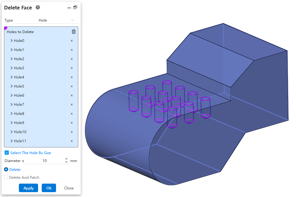
Usage - Manual Selection:
Open the "Delete Face" command.
Change the type to "Hole", and uncheck "Select The Hole By Size".
Click or box-select holes in the viewport to pick them.
Holes of the same size as the selected hole but not picked will be highlighted in green for selection.
Set "Delete and Patch" to ensure the solid can be patched after deleting the hole.
Click OK to complete deletion.
Usage - Automatic Selection:
Open the "Delete Face" command.
Change the type to "Hole", and check "Select The Hole By Size".
Set the hole diameter parameter.
Click or box-select holes in the viewport; all holes less than or equal to the specified diameter will be automatically picked.
Set "Delete and Patch" to ensure the solid can be patched after deleting the hole.
Click OK to complete deletion.
# Move Face
The Move Face command supports box selection of faces. For scenarios where multiple faces need to be moved simultaneously, box selection allows for quick selection, improving modeling efficiency.
# Assembly
# Unload
When unloading Instances, related Mates are automatically suppressed to avoid errors.
# Envelope
The Envelope feature has been added, allowing reference components to be set as an Envelope.
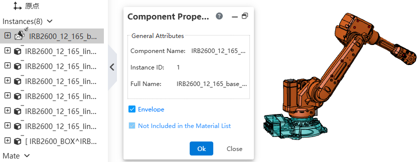
Usage:
Right-click the component instance to be set as an Envelope.
Select "component properties".
Check "Envelope", click OK to complete the setting.
Note 1: Envelopes will not be displayed in the Bill of Materials.
Note 2: In the Drawing, edit the view, select View Properties, to control whether to display the Envelope.
# External Reference
When deleting a Component, components that have External Reference relationships with it are retained.
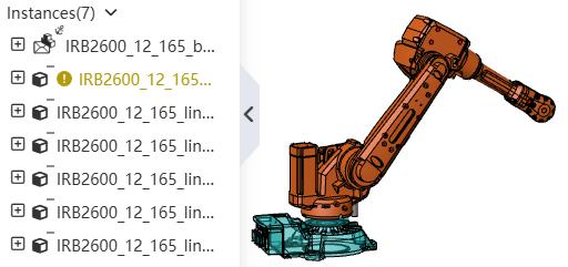
Sketches or Features that lose External References will display a prompt message. You can edit them to restore them to normal status.
# Drawings
# Line Type Scaling
Supports setting the scaling ratio for line types such as dashed lines, affecting the density of the lines.
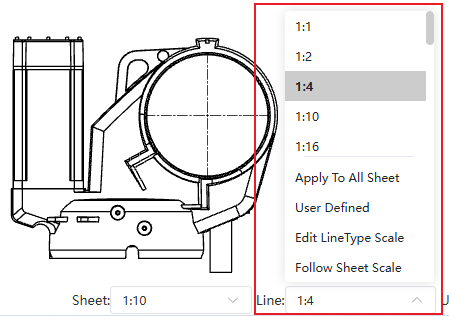
Usage:
Open the Drawing.
Click the line type dropdown in the bottom right corner.
Select the desired line type scaling ratio from the dropdown list.
Dialog Box Control Descriptions:
Apply to All Sheet: Applies the ratio to all sheets within the current Drawing.
User Defined: Allows customizing ratios not listed.
Edit LineType Scale: Allows editing ratios in the list.
Follow Sheet Scale: The line type scaling ratio is linked to the sheet scale. This option reflects the line type effect in CC 2026 R2 and earlier versions.
# Center Mark
Supports adding various styles of Center Marks to Slots.
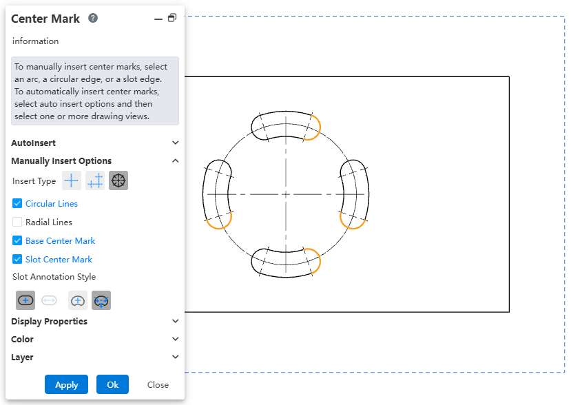
Usage:
Click the Center Mark command to open the dialog box.
Use AutoInsert to select Slots, or manually select slot edges in the viewport.
Modify the style of the Center Mark via Insert Type and Slot Annotation Style.
Click OK to complete creation.
# Note
Hovering over a Note displays its associated properties.

Usage:
Use the LinkToAttribute function in the Note command to create a Note with associated properties.
Hover over the created Note in the viewport; the associated properties will be displayed in the bottom right corner.
Note:
When double-clicking to edit the Note, the associated property will be highlighted with a blue background to distinguish it from regular text.
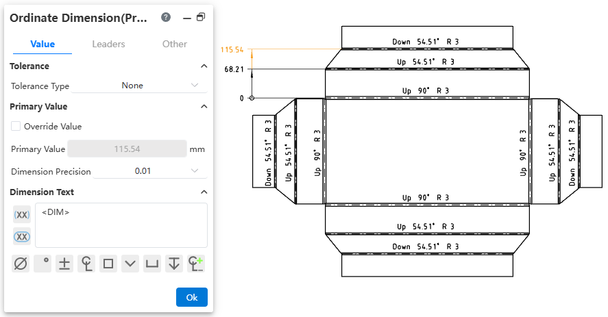
# Dimensions
Dimensions support dimensioning bend lines in Sheet Metal Flat Pattern views.
# Ordinate Dimension
Ordinate Dimensions support batch modification of tolerances, arrows, and other attributes.
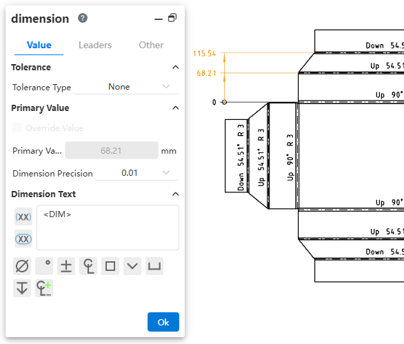
Usage:
In the viewport, select multiple dimensions of the Ordinate Dimension via box selection or by holding the Ctrl key.
Modify parameters in the Dimension dialog. The related parameters of the selected dimensions will be updated uniformly.
Click OK to complete the modification.
# Evaluate
# Section Properties
The Section Properties command has been added to measure relevant parameters of a section.
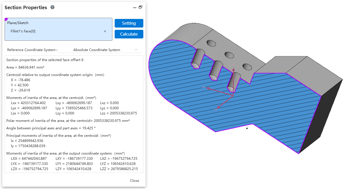
Usage:
Click the Section Properties command to open the dialog box.
Pick the face to measure. Supported selections include: "Closed Profile Sketch, Model Plane/Section, Multiple Parallel Faces".
Click Calculate, wait for the calculation to complete.
View the calculation results.
Note: Before measuring, you can use the Section View  command to create a section.
# Sheet Metal
# Base Flange
The Base Flange feature has added "Up to Vertex" and "Up to Surface" options to flexibly control the termination condition of the Base Flange.
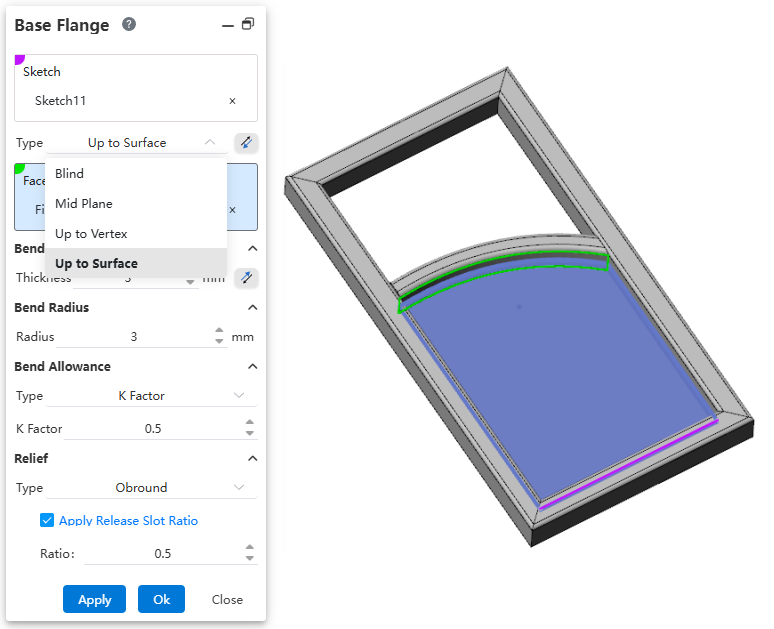
Usage:
Click the "Base Flange" command to open the dialog box.
Pick a non-closed profile sketch.
Select the option "Up to Vertex" / "Up to Surface".
Pick the point / face to terminate the extrusion.
Click OK to complete creation.
# Edge Flange
# Up to Vertex
The Edge Flange feature has added the "Up to Vertex" option to flexibly control the termination condition of the Edge Flange.
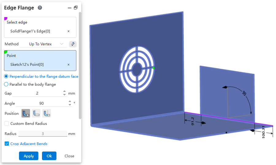
Usage:
Click the "Edge Flange" command to open the dialog box.
Pick an edge.
Select the option "Up to Vertex".
Pick the point to terminate the extrusion.
Set the point's action direction to "Perpendicular to the flange datum face" / "Parallel to the body flange".
Click OK to complete creation.
Dialog Box Control Descriptions:
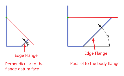
Perpendicular to the flange datum face: The action direction of the selected point is perpendicular to the Edge Flange.
Parallel to the body flange: The action direction of the selected point is parallel to the Base Flange.
# Apply Release Slot Ratio
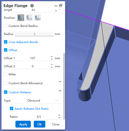
The Edge Flange feature has added the Apply Release Slot Ratio function, allowing control over the release slot size via a ratio relative to the sheet metal thickness.
Usage:
Click the "Edge Flange" command to open the dialog box.
Pick an edge.
Set the Offset so that release slots appear on both sides of the flange.
Check "Custom Release Slot", select the release slot type as "Rectangular/Obround", and check "Apply Release Slot Ratio".
Set the release slot ratio.
Click OK to complete creation.
Note: Ratio Value = Release Slot Width / Sheet Metal Thickness, Release Slot Length = Release Slot Width.
# Cut Vent
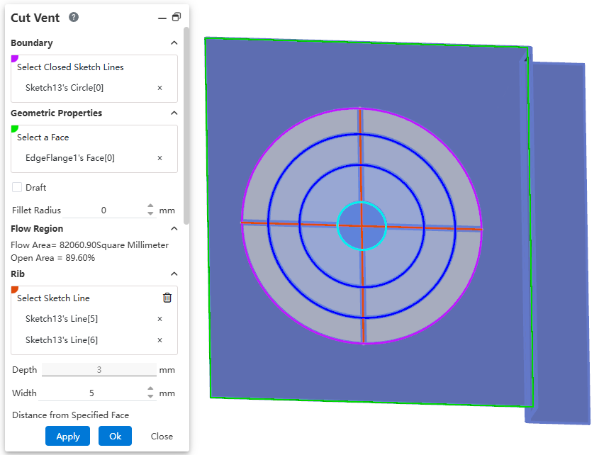
The Cut Vent command has been added to quickly generate vents on the model.
Usage:
Click the "Cut Vent" command to open the dialog box.
Select the boundary sketch to specify the external boundary of the vent.
Select the face where the vent will be created.
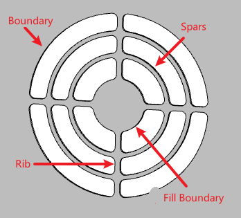
Select "Rib, Spars, or Fill Boundary" as needed.
Set parameters such as fillet radius.
This function involves many parameters. After configuration, click "Add or Update Favorite" to save the settings. Subsequently, parameters can be reused directly by selecting the favorite.
Click OK to complete creation.
Dialog Box Control Descriptions:
Boundary:
- Select Sketch Segments: Select sketch lines representing the vent boundary, supporting multiple lines combined into a closed profile.
Geometry Properties:
Select a Face: Select the face to place the vent.
Draft: Check to enable draft settings.
Fillet Radius: Sets the fillet radius at the intersections between the vent Boundary, Rib, Spars, and Fill Boundary. Set to 0 to add no fillet.
Flow Area: Automatically calculates the flow area of this vent based on the preview.
Rib:
Select Sketch Segments: Select sketch lines representing the Rib.
Depth: Sets the Rib depth. On sheet metal bodies, Rib depth is fixed equal to sheet metal thickness.
Width: Sets the Rib width.
Distance from Specified Face: Sets the offset distance from the Rib's starting position to the face.
Spars, Fill Boundary: Similar to Rib, the related parameters control "Spars" and "Fill Boundary" respectively.
Favorites:
Dropdown: Used to select saved parameters.
Add or Update Favorite: Used to create a new favorite with current parameters or update an existing favorite.
Delete Favorite: Used to delete an existing favorite.
# Weldments
# Structural Member
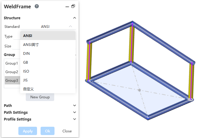
The Structural Member standards have been expanded, adding "ANSI, ANSI Inch, DIN, JIS" standards.
# Weldment Properties
Bodies generated by Pattern Mirror operations can retain Weldment Properties, supporting the use of Trim/Extend and viewing Cut List Attributes.
# Rendering
# Edit Appearance
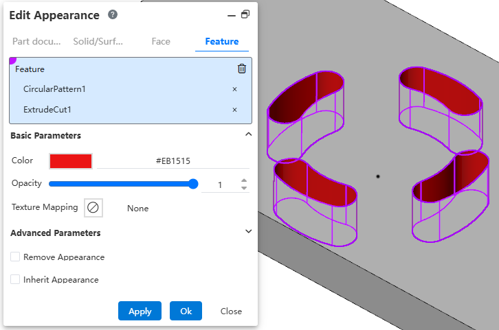
The Edit Appearance command has added a Feature level, making it convenient to apply appearance to faces related to features.
Usage:
Click the "Edit Appearance" command to open the dialog box.
Select the "Feature" tab.
Pick a feature in the viewport or the Feature panel.
Set parameters, click OK to complete the setting.
Note: Appearance priority "Face > Feature > Solid/Surface > Part".
# Library
# Material Repository
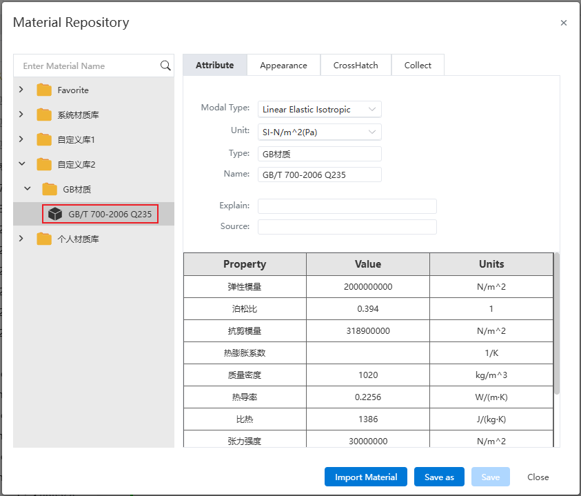
- Material names support "/", allowing for the recording of GB/T related material names.
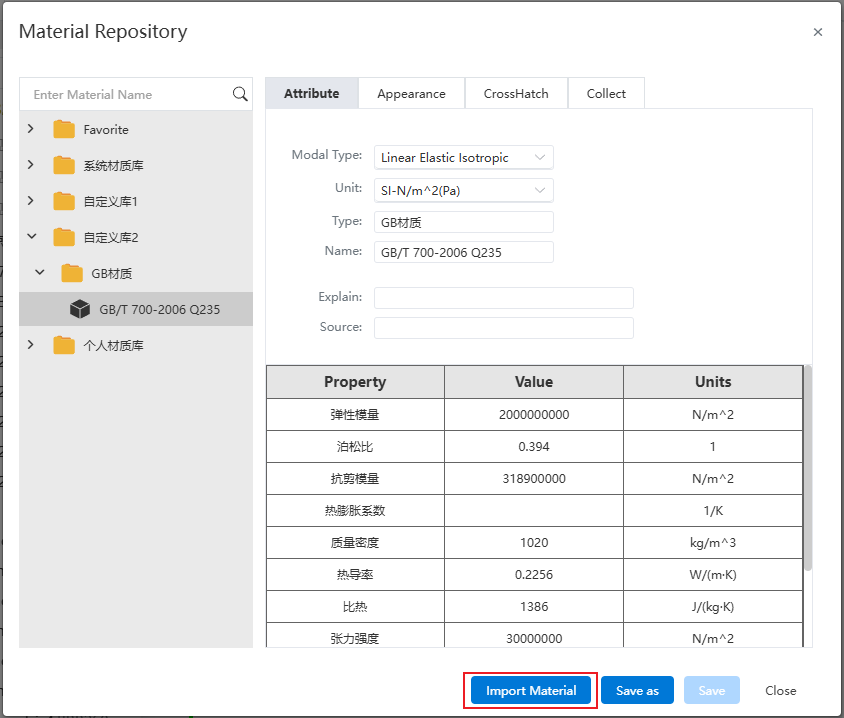
- The Material Repository has added an "Import Material" button to quickly upload custom materials.
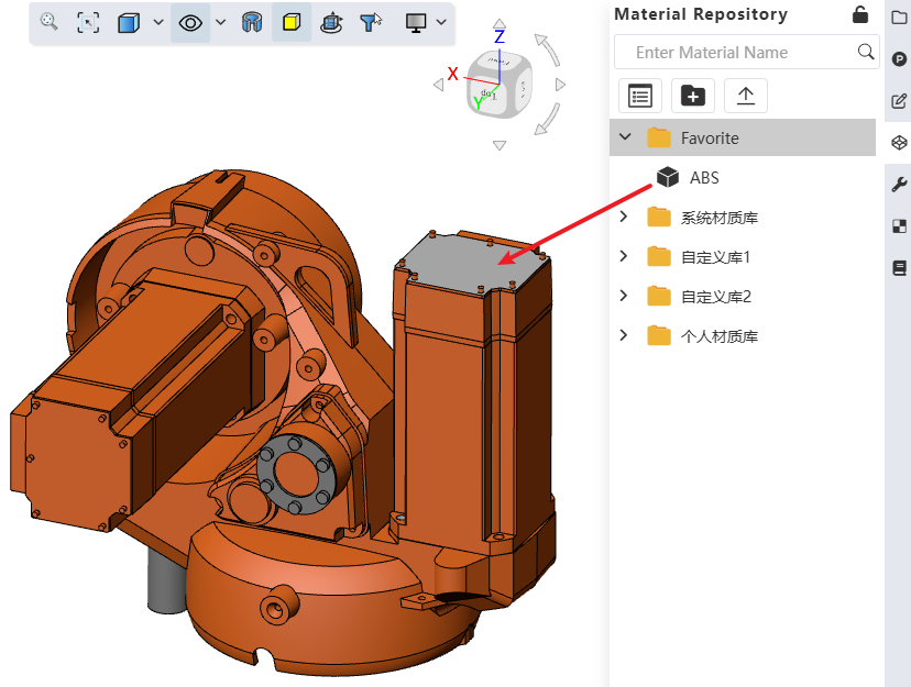
- Materials in the right-side material panel support direct drag-and-drop application, improving modeling efficiency.
# Standard Part Library
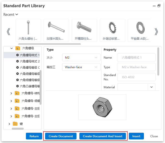
- After selecting a Standard Part, documents can be generated directly within the Project.
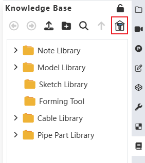
- The "Knowledge Base" interface has added a quick access shortcut for the "Standard Part Library".
# BOM
# Custom Properties
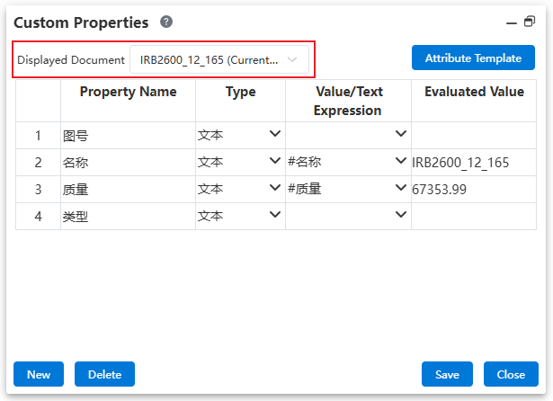
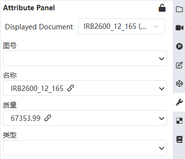
Custom Properties and the right-side Attribute Panel support switching the displayed document. In an assembly, you can directly modify component properties.
# BOM Tools
The default template for exporting to Excel has been optimized to align with the default order of attributes in the BOM Tools dialog box.
Note: The content exported to Excel is controlled by the selected template. You can customize the table template in "System Setting - System Option - Template Management - BOM Export Template".
# Applications
# Project Documents
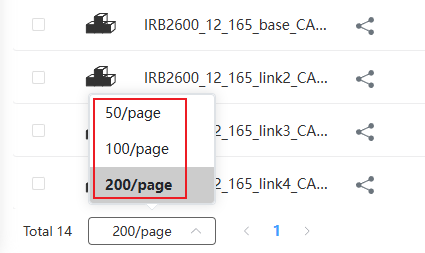
- Supports saving the number of items displayed per page for Project Documents. Once set, the option is retained when switching to other Project Documents, avoiding the need for repeated configuration.
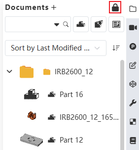
- Supports saving the lock status of the right-side Document List. Once set, the lock status of the side panel is retained when switching to other documents, avoiding the need for repeated configuration.
# Scrollbars
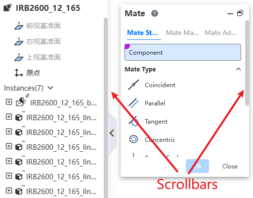
Scrollbars in interfaces such as the Feature Panel and Dialog Boxes have been uniformly thickened for easier drag control.