
# Custom Properties
# Custom Properties
Directly click the BOM toolbar - [Custom Properties] (or right click the document name in the feature panel, click [Custom Properties]), the property box appears, the default common attribute content is: picture number, name, material (only parts, assembly without this option), quality.
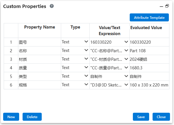
Click the "Displayed Document" dropdown box to switch to display properties of other components.
Click the Property Template button to switch to another document property template. Click OK Replace after selecting the template from the drop down box. When switching templates, ask the user if they want to clear the existing properties.
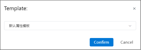
- Select Clear: Delete existing property entries and property values and add property entries to the template.
- Select Not Empty: Keep existing property entries and property values and add property entries in the template. (Do not re-add existing property entries).
- Property name, Type, Value/Text Expression,Evaluated Value
Property name: The name of the property entry.
Click to select the property row for deletion.
Double-click to enter edit mode for the property name.
• Type: This is a drop-down list with options: "Text", "Number", "Date", "Yes or No".
Text: The property value can be any text input, or selected from a drop-down list. The options in each property's drop-down list are controlled by the "Optional Property Values" in the "Property List".
Number: The property value can only be a numeric input.
Date: The property value can only be in the format xxxx.xx.xx, with a format prompt during input.
Yes or No: The property value is a drop-down list, with only "Yes" or "No" as options.
The default type for all properties is "Text".
Value/Text Expression: Input or select the parameter corresponding to this property.
Click the triangle icon to expand the drop-down list for selection.
Manual input is also allowed as needed and must comply with the requirements of the selected type.
Evaluated Value: Displays the final property value based on the Value/Text Expression.
Add: Click to display the Add properties dialog box.
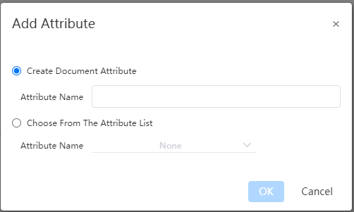
- Optional "Create Custom properties" or "Choose from Properties template", single option.
- Select "Create Custom Property" and enter the property name to create the property. The default is text type. The property entry created here does not affect the property template.
- You can add the selected properties to the current document by selecting "Select from Properties Template" and selecting the properties in the current document properties template from the drop down box. The drop down box only displays properties that are in the property template, but not in the current document.
Delete: When any property is selected, the button is clickable. Click the pop-up confirmation dialog box and delete the selected property after confirming.
Billet Size:Click this button to start the blank calculation command.
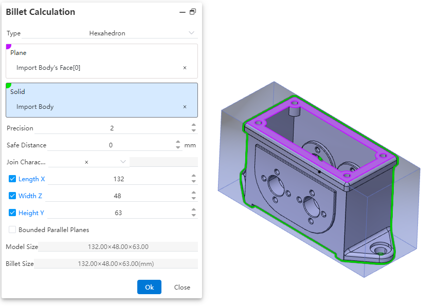
Control Description:
Type:Select the type of blank material, which can be either a hexahedron or a cylinder. Different types have different parameter items.
Plane:Choose the reference plane for creating the blank, which can be a solid plane, a curved plane, or a datum plane.
Precision:Control the display precision of the blank dimensions. You can manually input a number, adjust it using the mouse wheel, use increment/decrement keys, or enter a mathematical expression. Variables are supported.
Safety Distance:Adjust the amount added to the outer contour of the blank. The default value is zero, and both positive and negative values can be set.
Connection Character:Set the symbol used to connect the dimensions of the blank. Four types are provided, with the default being "×". You can choose from "×", "*", "-", or directly input any character.
Length/Width/Height:By default, these dimensions are automatically calculated based on the safety distance. You can manually input values, but after manual input, the safety distance will recalculate and revert to the automatically calculated values.
Bounded Parallel Plane:Control whether to create a parallel plane for the reference plane of the blank. If selected, the safety distance cannot be set, and the input fields for length, width, and height will be grayed out, preventing manual input.
Model Dimensions:Display the dimension parameters of the selected model after picking a plane or solid.
Blank Dimensions:Display the dimensions of the blank after the parameters are set.
How to use
Open Custom Properties.
Create a new property as needed.
In the row where you want to set the property value, click Value/Text Expression. Add an expression using one of the following methods:
a. Text: Enter text or symbols directly.
b. Dimensions: In the viewport or the Feature Manager, double-click the feature or sketch containing the dimension. Once the dimension is displayed in the viewport, click the dimension to add it to the expression.
c. Units: Click the dropdown arrow to the right of Value/Text Expression, and select the desired unit type from the dropdown menu.
d. Global Variables: Click the dropdown arrow to the right of Value/Text Expression, and select the desired global variable from the dropdown menu. Prerequisite: A variable must have been manually created in the document to use this function.
e. Properties: Click the dropdown arrow to the right of Value/Text Expression, and select the desired property from the dropdown menu. Available properties include the current document's name, material, owner, mass properties, and other information.
Check the Evaluated Value to see if the property value meets expectations. If not, modify it in Value/Text Expression.
Continue adding, deleting, or modifying properties as needed.
Click Save to complete the setup.
Notes:
Property Expression Content: A single property expression can combine multiple types of information, such as text + dimensions.
Numerical Precision:
The dimension precision of sketch dimensions follows the setting of the dimension itself.
The precision of variables, feature dimensions, and mass properties follows the precision setting under System Settings - Document Properties - Units.
Zero Value Display: The zero value display rule for each value follows the setting under System Settings - Document Properties - Dimensions - Zero Value Display - Property.
Units: The specific units for each type of value follow the setting under System Settings - Document Properties - Units.
The numerical precision, zero value display, and units of a property are controlled by the document property settings of the part/assembly document where the property resides. When generating drawings, the property value content is independent of the drawing's document property settings.
How to use-Billet Calculation:
Click on BOM - Custom Properties to start the command.
In the numerical/text expression dropdown menu of any row, choose Blank Dimensions to display the current blank dimensions in the evaluated value field.
Click the Blank Dimensions button to begin the blank calculation process.
Select the type of blank calculation required
Choose the reference plane and relevant entities within the part for blank creation.
Adjust the display precision settings to control how blank dimensions are shown.
Specify the addition amount for the blank's outer contour.
Set the connection symbol used between blank dimensions (e.g., "×", "*", or "-").
Manually input or utilize automatically calculated values for length/width/height.
Determine whether to create a bounded parallel plane for the reference.
Click OK to complete the blank calculation. The new dimensions will be populated into the evaluated value field.
# Properties panel
Custom properties can be quickly set through the right [Properties panel]
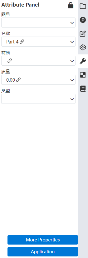
1)When the document is opened, the properties panel can be opened on the right side, as shown in the picture above.
2)Setting properties in the Properties panel has the same effect as setting properties through the document Properties command.
- The property entry in the panel and the contents of each property drop-down menu are the same as the document property command.
3)Click more properties to open the Document Properties dialog box. When the dialog box opens, do not close the custom properties panel. All buttons and options in the panel are gray and cannot be modified temporarily.
4)When the document is closed, the properties panel prompts whether to apply the Settings if they are not applied
- After clicking Apply, the Settings in the panel take effect and write the document properties.
- When you do not click Apply or close the panel, the prompt "There are unapplied Settings in the properties panel, apply it or not" pops up.
- Select Apply, then the Settings in the panel take effect and document properties are written.
- If you select Discard, you discard the Settings in the panel.
# Displaying Multi-Document Properties
In an assembly, when multiple parts or sub-assemblies are selected, the Attribute Panel and Custom Properties dialog can simultaneously display the property content of the selected documents, facilitating batch property settings.
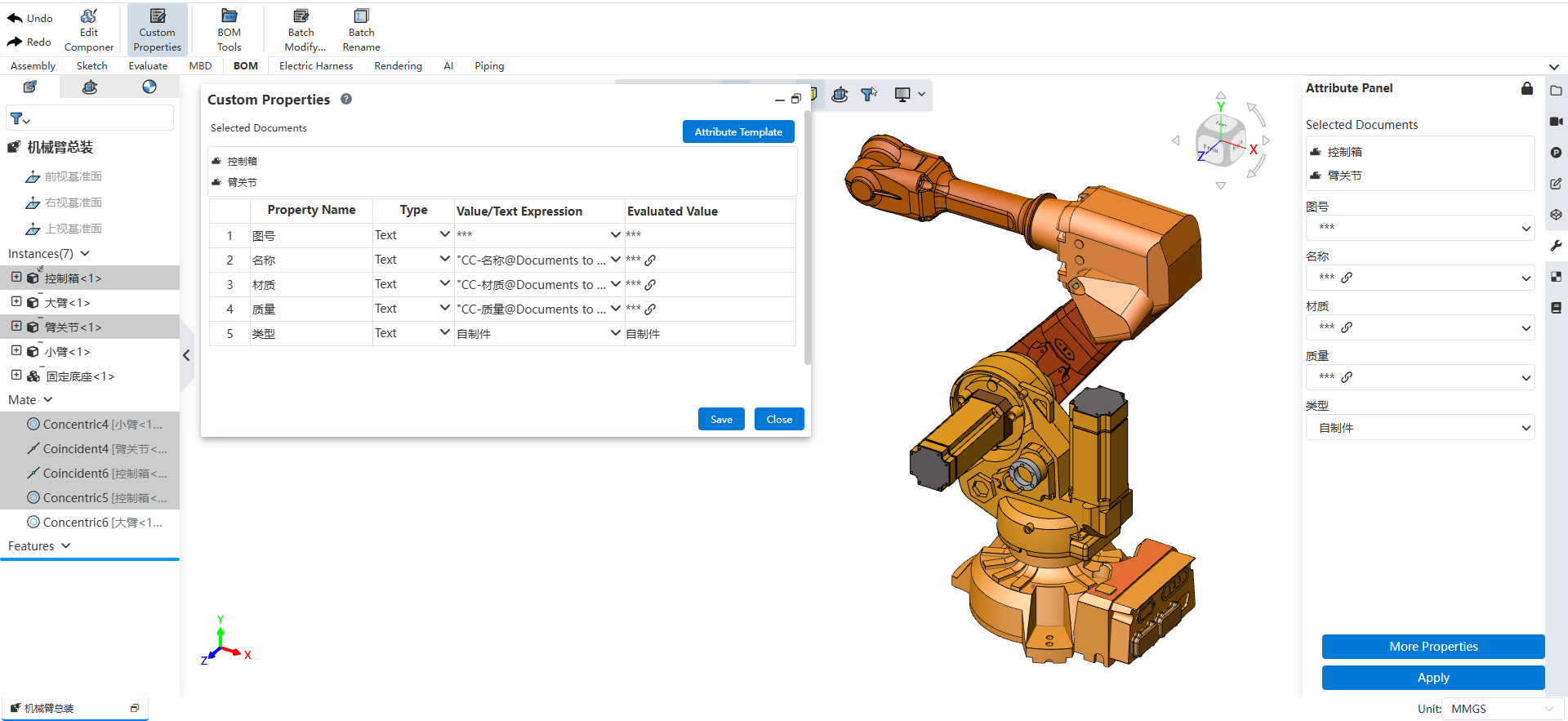
Usage:
In an assembly document, click the "Attribute Panel" on the right to open the panel, or open the "Custom Properties" command dialog.
Click the "Lock" icon at the top right of the panel to keep the panel expanded.
Hold down the Ctrl key and select multiple parts or sub-assemblies in the viewport or in the Feature Manager on the left.
The content of the Attribute Panel displays the properties of the selected components. For properties with different values, "***" is displayed; for properties with identical values across all selected components, the specific value is shown.
Modify a property value, and the corresponding properties of all currently selected components will be updated synchronously.
Click Save/Apply to end the modification.
Note 1: When selecting multiple documents, their document types must be the same (e.g., all parts or all assemblies). Mixing parts and assemblies will prevent property information from being displayed.
Note 2: The "Custom Properties Template" of the selected documents must be the same. When multiple documents are selected, only the properties defined in the Attribute Panel are displayed; individually added properties in a document are not shown. You can switch the "Custom Properties Template" by clicking the "Property Template" button in the Custom Properties dialog.
Note 3: The selected documents must not be in an unloaded state.