# Welcome to CrownCAD 2025 R3
CrownCAD 2025 R3 extensively incorporates real-time user feedback and maximizes the fulfillment of customer needs. In terms of usability, we are committed to enhancing the customer experience; in functionality, we continuously add commands that customers urgently require, helping you quickly complete product design and development work.
Key Enhanced Features:
| Sketch | Enhance the “Trim” function to control whether it affects Construction. |
| Add the “Centerline” function to facilitate quick drawing of reference lines. | |
| Optimize “Symmetry Constraint” logic using Construction or Plane as symmetry axes, enabling users to add symmetry constraints for three symmetric elements; simultaneously support constraints involving elements outside the sketch. | |
| The sketch text supports custom fonts and additional settings. | |
| Feature | The “Extruded Boss” ‘Merged Results’option has been optimized to better suit weldment design scenarios." |
| Supports creating multiple solid via feature operations at once. | |
| Assembly | A new 'Mate Folder' feature allows viewing and organizing mates added by each component within the parent assembly, accessed via the Assembly Features panel in folder format. |
| Interaction during mate editing has been optimized; clicking Ok without modifying any parameters no longer displays a prompt. | |
| A new 'Edit Feature' function enables users to directly enter the part edit mode and either open the feature dialog box for modification or access the sketch that needs editing. | |
| A new quick display feature for triple axes enables users to rapidly show components' triple axes and utilize them for movement/rotation instances. | |
| A new “Component Preview Window” feature allows users to view selected componentswithin the assembly window without opening separate documents. | |
| The enhanced “Insert Component” command now supports setting whether to display the shortcut menu for rotated components. Additionally, a new 'Open Document' page makes it easy to quickly insert documents currently open in the project. | |
| A new 'Dissolve Sub-Assembly' feature lets you dissolve existing sub-assemblies. | |
| The 'Show Hidden Components' feature now supports rectangular box selection, making it easier to batch select and view hidden components. | |
| The Mirror/Pattern functionality has been enhanced, enabling the created components to be mated with other existing components. | |
| A new “Flexible Assembly” feature has been introduced, allowing individual components of a sub-assembly to be moved freely within the main assembly. | |
| The new “View Component Material” feature enables you to expand components in the assembly instance list to view their material properties, making it easier to check and manage different materials used across your design. | |
| Annotation | The Break View command has been enhanced with drag support to adjust the break position. Additionally, when projecting from a parent break view, child views now automatically inherit identical break features. |
| A new “Caterpillar” feature has been introduced, allowing users to create annotations that clearly identify and outline weld bead in their designs. | |
| The “Smart Dimensions” function has been expanded to include dimensioning of center marks on both circular and linear connections, streamlining the documentation process. | |
| Enhanced engineering drawing tables now allow users to save their data in various local file formats, such as Excel (.xlsx), for improved flexibility and seamless integration with external software. | |
| Enhancements and optimizations for “Geometric Tolerance” commands, supporting the combination of frames with similar geometric tolerances; supports adding text before and after geometric tolerances; introduces a new symbol library to enable the insertion of a wider variety of symbols; optimizes frame alignment effects. | |
| Enhancements to hole table commands, supporting the ability to jump to tags in the hole table for quick determination of hole positions; supports simultaneous selection of X and Y axis directions to generate the hole table; supports re-editing of coordinate directions in the hole table. | |
| A new “End Treatment” function has been added to generate markings for weld cross-sectional views. | |
| A new ”Dowel Pin Symbol” function has been added to add dowel pin symbol annotations to round holes. | |
| Sheet Metal | A new feature for “Export To DWG/DXF” files has been added, enabling one-click export of drawings containing views of the sheet metal unfolding model's outer contours. |
| Enhancements to the “Extruded Cut” functionality include an added “orthogonal removal” option when removing sheet metal solids, enabling the quick creation of models that conform to sheet metal characteristics. | |
| Optimization of the Edge Flange command. When using the Edge Flange, the parameters under "Method" will default to the previously used options. | |
| A new Corner Relief command has been added, which allows for processing of existing sheet metal corners. | |
| Weldments | A new Weldment command has been added, which allows ordinary part documents without structural members to be converted into Weldment parts. |
| A new "Insert into New Part" feature has been added, which allows the solids/surfaces from the current document to be inserted into a new part for further operations. | |
| Data Conversion | Import formats have been increased, and a new feature allowing the import of Emp, emn, and vda formats has been added. |
| Enhanced import functionality now supports reading spatial points from Creo\UG\CATIA\SW models during the import process, and these spatial points are imported as "reference points" into Crown CAD. | |
| A new "Export Curves" feature has been added, allowing simultaneous curve export during model export while providing detailed settings for the exported curves. | |
| A new "Export" function has been added, enabling support for the "STEP AP242 (*.step)" format. This format includes options to specify whether to export MBD (Model-Based Definition) and hidden MBD within the file. | |
| A new 'Export Rename' feature has been added, enabling users to rename files during the export process. | |
| MBD | A new 'View Orientation' feature has been added to the assembly, enabling users to choose projection views based on specific orientations in the engineering drawing. |
| Settings | A new “lineType” option has been added to the settings, which allows users to configure specific line styles for different edge types within engineering drawings. |
| A new “lineWidth” option has been added to the settings, allowing users to manage line width in engineering drawing configurations. | |
| A new “Model Display” option has been added to the settings, which supports coloring and surface color settings. | |
| A new option has been added to the sketch settings: 'Auto-rotate view to be vertical with respect to the sketch plane when creating or editing a sketch. | |
| A new 'Use shaded face highlighting' option has been added to the display settings. | |
| The 'Enable picking objects through transparent faces' setting has been optimized for better interaction, allowing temporary toggling of its state with the Shift key. | |
| In the drawing colors section, new configurable color types have been added to provide enhanced flexibility in selecting appropriate colors. | |
| Library | Engineering drawings can now reference content from a sketch library and support inserting sketches saved in any location within the knowledge base. |
| For assemblies, the 'Standard Part Library' functionality has been enhanced to allow customizing the length of standard parts during insertion. | |
| Rendering | The rendering effect of the Sectional View has been optimized so that when the 'show cutting line' option is selected and the 'show section cap' option is deselected, the cut surface displays the actual color of the part. |
| Project Documentation | Project management has been optimized, supporting drag-and-drop to move projects and folders; additionally, it also supports setting the arrangement of account settings lists. |
| Optimize the help manual, after enabling the help, update default command to target the first tab page. | |
| Added a function to transfer the ownership of an entire folder while maintaining its internal file hierarchy. | |
| Synergia | The "create activity" function has been enhanced to include a feature for statistics on participant information. |
| Add a new restriction when adding to the activity to prevent a single participant from entering through multiple channels. | |
| Support submitting works via folder import, optimize the status of individual/team folders when imported into the activity module. | |
| Add a tagging feature to projects and teams, enabling tag assignment for team-created projects and quick project retrieval via tag-based filtering. | |
| Optimize permission controls for different roles (such as creators, members) when operating on multiple projects or folders in multi-select scenarios. | |
| Add functionality to view individual/team project creator information. | |
| Add functionality transferring team project ownership, including top-level folders during the transition. |
# 草图
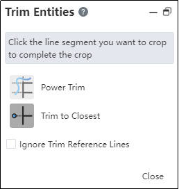
# 剪裁
新增“忽略对参考线的剪裁”功能,勾选此项后,在剪裁过程中不会影响到参考线。
# 中心线
插入线条命令新增中心线功能,以便快速绘制参考线。

使用方法:
1) 进入草图。
2) 单击直线下拉框的中心线命令。
3) 在视口中依次单击,指定线的端点,绘制的线为参考线类型。
4) 可以连续绘制多段线。
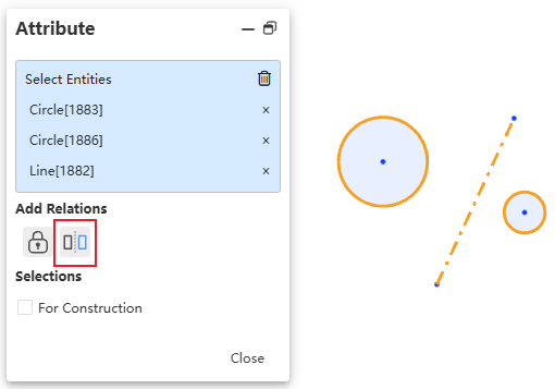
# 对称约束
优化对称约束逻辑,并支持与草图外元素进行约束。
说明:
1) 您可以拾取当前草图内的一条参考线,或与当前草图垂直的一个基准面作为对称轴。
2) 拾取三个可以对称的元素即可添加对称约束,没有拾取顺序要求。
3) 您可以拾取草图外元素添加对称约束。
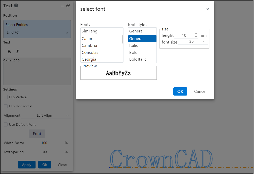
# 字体
草图字体支持自定义字体以及更多设置。
使用方法:
1) 打开“系统设置-系统选项-模板管理-字体”,使用新增功能上传自定义字体。
2) 进入草图。
3) 创建草图文字。
4) 取消“使用默认字体”,单击字体按钮,在弹出的对话框中选择字体并进行相关设置。
对话框控件说明:
字体:在列表中选择需要使用的字体。
字体样式:可以选择不同的字体样式,如加粗、倾斜等。
大小:可以通过高度或字体方式来调整字体大小。
预览:查看当前设置的预览。
# Features
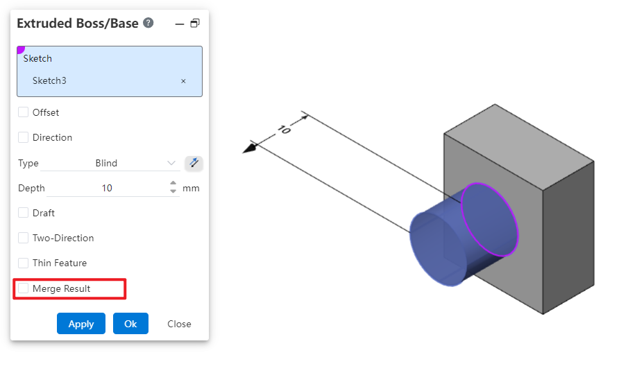
# Extruded Boss/Base
Optimization of the ' Merge Result' option:
In documents where welds exist, the ' Merge Result' option is set to be unchecked by default. This better meets the needs of weld design scenarios.
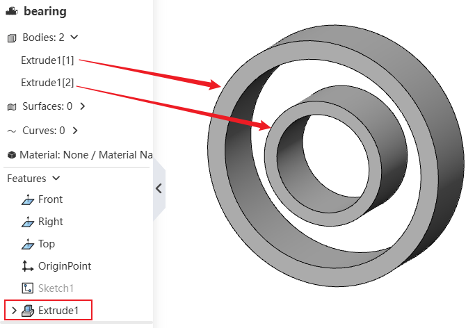
# Multi-body
Solid features support creating multiple solids in one step, including the following commands: “Extruded Boss/Base,Extruded Cut, Revolved Boss/Base, Revolved Cut, Swept Boss/Base, Swept Cut,Lofted Cut”.
Extrusion Method to Create Multiple Solids:
1) Create a sketch with multiple disconnected profiles.
2) Use the Extruded Boss/Base command to select this sketch.
3) Proceed to create the extrusion feature normally. Each disconnected part will be recognized as a separate solid.
Cutting Method to Create Multiple Solids:
1) Create a sketch that can completely section the solid(s).
2) Use the Extruded Cut command to select this sketch and set the depth deep enough to completely punch through the solid(s).
3) Proceed to create the Extruded Cut feature normally. After cutting, each disconnected part will be recognized as a separate solid.
# Hole Wizard
# Hole Center Point supports 3D sketch
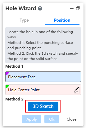
Usage:
1) Open the Hole Wizard command.
2) Specify hole type and parameters.
3) Click the 3D Sketch button to enter 3D sketch mode and launch the Point Creation command automatically.
4) Click directly on the face to capture it and display the hole preview.
5) Exit the sketch, click OK to finish hole creation.
# Capable of creating holes on multiple solids
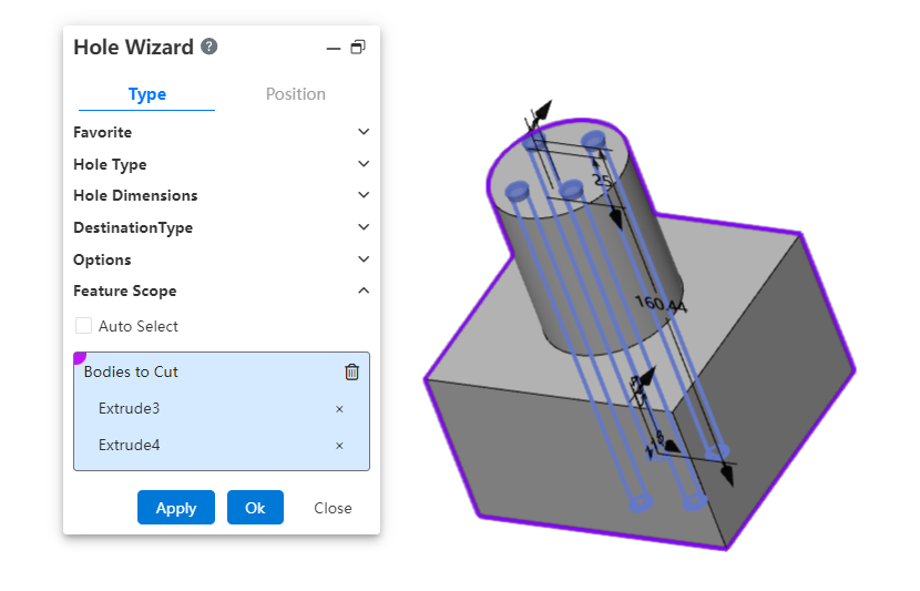
Usage:
1) Launch the Hole Wizard command.
2) Define the hole's type, parameters, and position.
3) In the Feature Scope option, select the target solid(s) for hole creation; you can either automatically capture or manually specify them.
4) Click OK to complete the operation.
# Supports adding head clearance and countersink
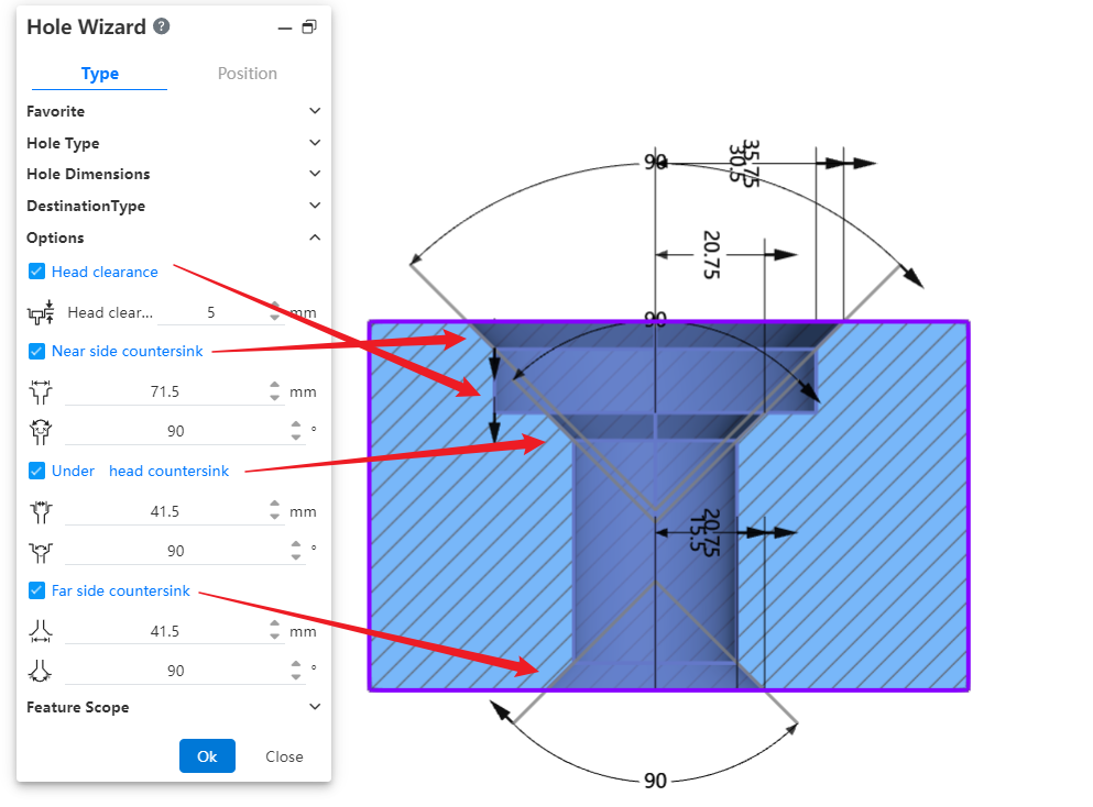
Dialog Control Description:
- Head clearance:
Checking this option adds depth to the recessed area above countersunk or buried holes, and the added dimension can be set by the user. For buried holes, you can also choose how the depth is increased.
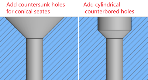
- Near side/ Under/Far Countersink:
Checking this option allows you to add Countersink features with angled shapes at designated positions on the model. The feature dimensions (distance and angle) can be defined as needed.
# Delete Body
A new "Delete Body" command has been added, allowing you to delete specific bodies during the modeling process. This operation will be recorded as an editable feature in the Feature Panel.
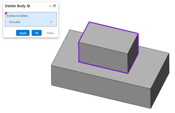
Usage Instructions:
1) Right-click on the body in the Feature Panel.
2) Select the "Delete Body" option from the right-click menu.
3) Choose the body you want to delete.
4) Click "OK," and the selected body will be deleted while generating a corresponding feature for future editing.
# Assembly
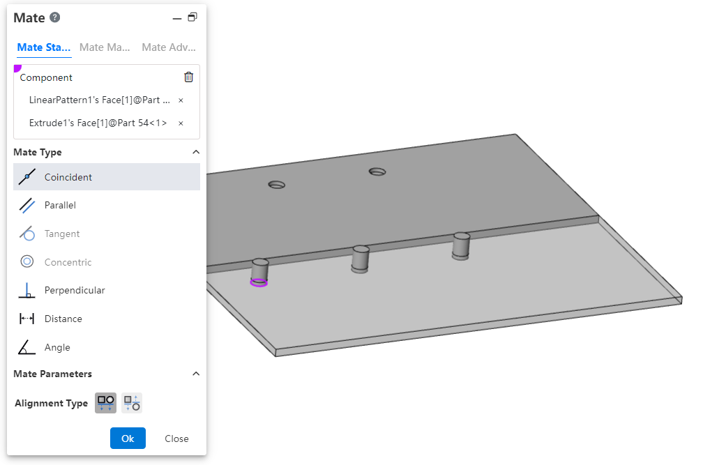
# Mate
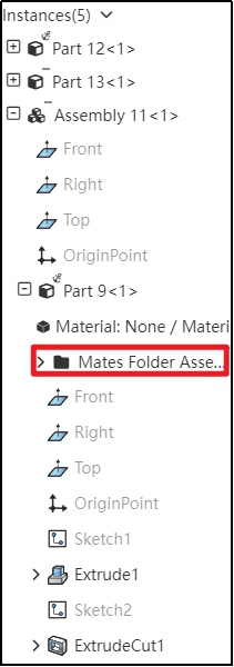
# Mate Folders
Within the Assembly Features panel, expand the components to view their mate folders, allowing you to easily see which mates have been added for each component in the parent assembly.
# Edit Mate Optimization
When editing a mate without modifying any parameters, after clicking 'OK,' no prompts will appear again. This optimization improves the user interaction experience."。
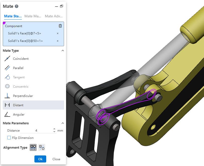
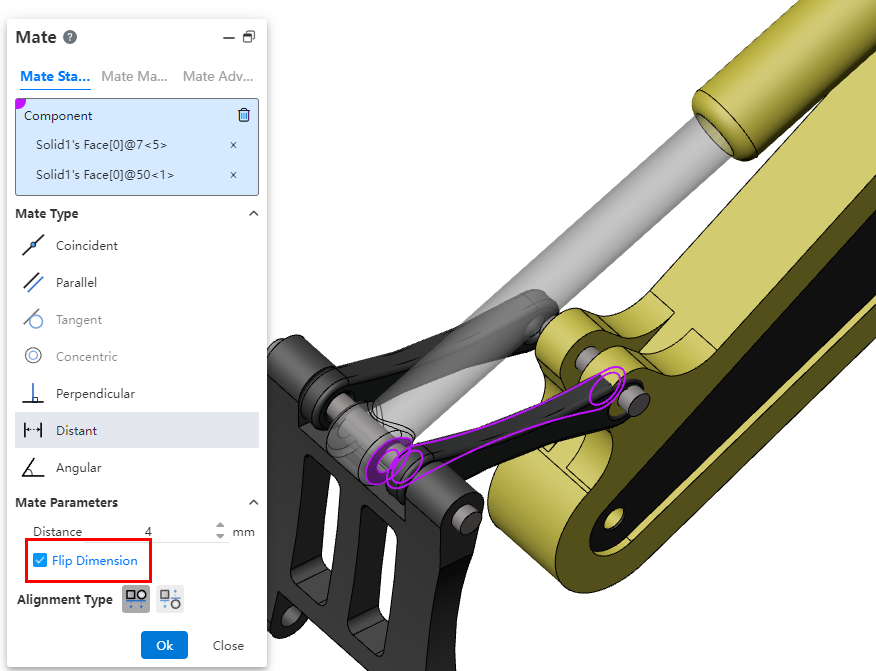
# Reversing Dimensions
When adjusting the numerical direction of mating parameters, use the 'Reversing Dimensions' feature to control their orientation.。
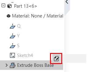
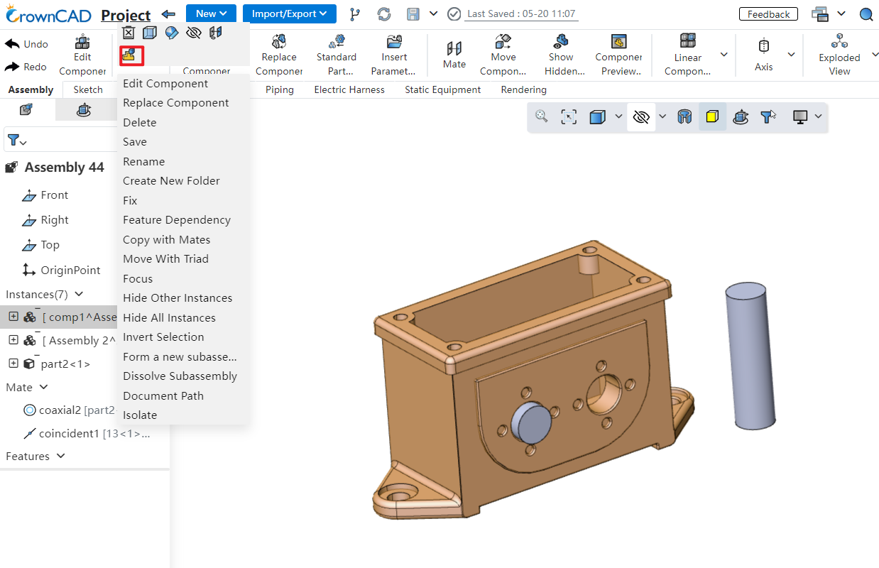
# Editing Features
In an assembly, right-clicking on a part's feature and selecting 'Edit Features' allows you to directly enter the editing state of the part and opens the 'Edit Features' dialog box. This function also applies to component sketches.
# Translate/Rotate
In the assembly, you can quickly display the triad of components and use the triad to translate/rotate components.
Method of Use:
1) Open 'System Settings - System Options - Assembly'.
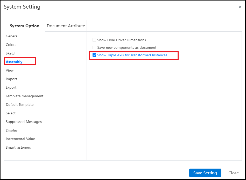
2) Check 'Show Triad for Transformable Instances'.
3) Open the assembly document.
4) In the Feature panel, click the component instance you want to move.
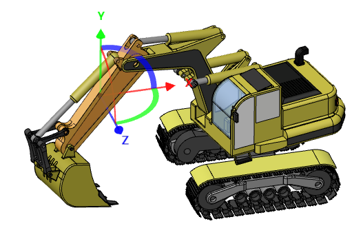
5) The selected instance will automatically display a triad. Drag the triad to move or rotate the component instance.
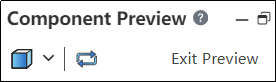
# Components Preview Window
A new 'Components Preview Window' feature has been added, enabling you to view selected components within the window while working in the Assembly Document without needing to open a separate document.

Using the Components Preview Window:
1) First, select the component instance you want to view in the viewport or Feature panel.
2) Next, click on the "Components Preview Window" command.
3) The selected component will appear in a split-screen window on the right side of your screen for previewing.
4) You can modify the display properties of the component within the assembly document and also synchronize the views between the preview window and the main assembly view.
5) Click to exit preview and end the viewing.
The Explanation of Dialog Box Controls:
Set the display style of the current preview component in the main assembly window.
Synchronized Views: Click this option to make the view of the main assembly window and preview window synchronized.。
# Inserting Component Rotation
During the insertion of components, the system supports displaying a quick menu for rotating the component, which makes it convenient to set its direction.
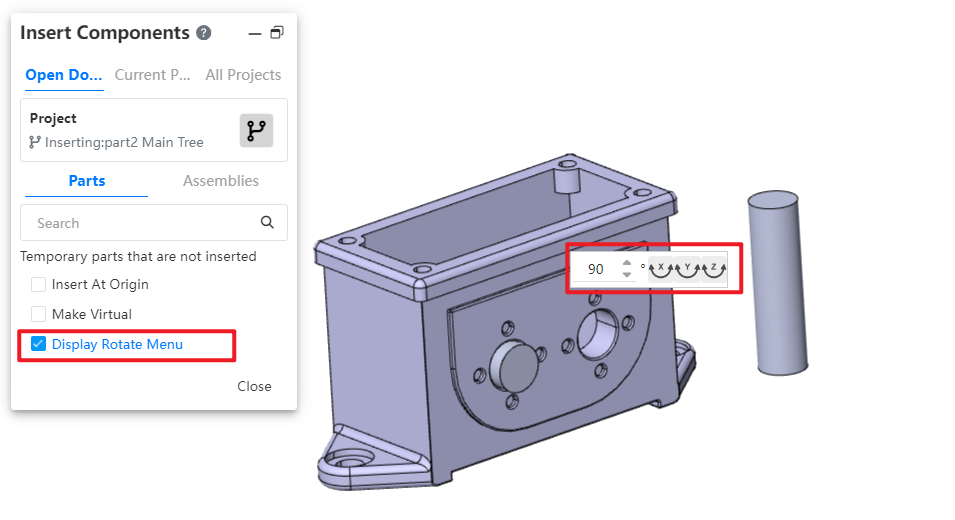
Usage Instructions:
1) Open the Insert Part or Assembly command.
2) Activate the "Show Rotation Menu" option.
3) Select the component you wish to insert.
4) Position your mouse in the viewport to display the rotation features' shortcut menu.
5) Input the desired rotation angle.
6) Click the XYZ button; the component will rotate around the corresponding axis by the entered angle.
7) Additionally, press the Tab shortcut key to rotate the component 90° around the Y-axis.
8) Click in the viewport to insert the selected component.
# Feature Adaptation
The following functionalities are now adapted to assembly documents and can be used in assembly document.
The "point-normal" type of reference plane supports the option of "percentage of curve length," allowing you to control the generation position of the reference plane by specifying a percentage on the curve.
Reference Lines: Added "Angle Bisector, Tangent to Curve, Point and Straight Line" Types.
To learn more about the features, please refer to the corresponding commands in the part module user manual.
# Disassembling Sub-Assemblies
Added: New Function – Disassembling Sub-Assemblies.
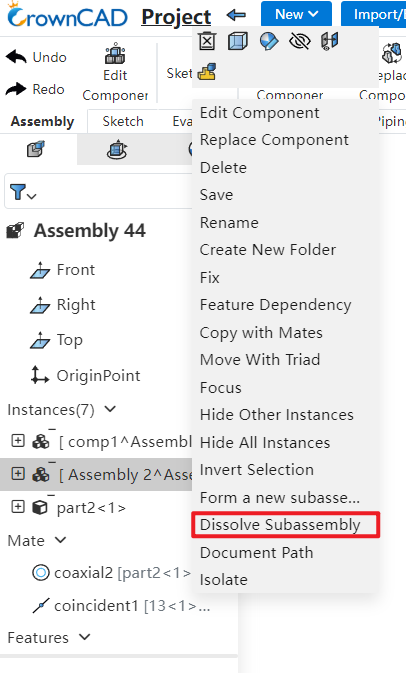
Usage Instructions:
1) Right-click on the sub-assembly you want to disassemble in the FeatureManager panel.
2) Click on the 'Dissemble SubAssembly' option.
3) If there are virtual components or features that cannot be preserved, a system prompt will appear.
4) Upon confirmation, the sub-assembly will be disassembled.
# Show Hidden Parts
Enhancement of the 'Display Hidden Parts' Feature: Now Supports Box Selection for Efficient Batch Component Selection.
Method of Use:
1) Click on the "Display Hidden Parts" command to activate the functionality.
2) In the viewport, draw a bounding box around the components you want to display.
3) Use the "Undo" button to remove any unintended selections from your current selection set.
4) Finally, click the "Exit Show-Hide" button to complete the operation and return to normal viewing mode.
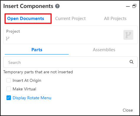
# Insert Components
The "Insert Parts or Assembly" function has added an "Open Document" page, allowing users to quickly insert open documents from the current project within it.
# Mirror Components/Component Patten
Mirror or array-generated components can be mated with other components, improving the flexibility of adding mating in assemblies.
Note: Curve arrays and array-driven array instances are currently unsupported for this feature.
# Flexible Assembly
Added a new Flexible Assembly feature, allowing the movement of individual components within subassemblies in the main assembly.
Usage Instructions:
1) Right-click on the subsystem containing the components you want to move.
2) Click "Make Subassembly Flexible."
3) Drag the components within the flexible subsystem; they can move independently.
Notes:
Components will move according to the existing constraints when dragged.
Adjusting positions within a flexible subsystem does not affect the original component locations in the source document.
Right-click the subsystem again to restore rigidity, reverting components to their original positions.
# Display Component Materials
Within the assembly instance list, expanding a component's hierarchy lets you view its material attributes.

# Drawing
# Break View
- Support dragging the fracture line to change the fracture position.

- When projecting with a fracture view as the parent view, the child view automatically generates the same fracture features as the parent view.

Explanation:
The fracture position of the child view updates according to the fracture position of the parent view and cannot be manually adjusted.
Fracture features are automatically generated only when the projection direction aligns with the fracture line direction.
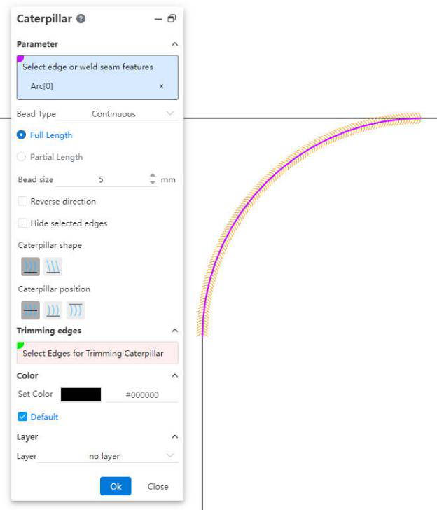
# Caterpillar
Added a " Caterpillar " feature to generate annotations for identifying welds.
Usage Instructions:
1) Click the " Caterpillar " command.
2) Select the edge in the viewport, or expand the component in the view panel to select the weld feature.
3) Set the Caterpillar style, parameters, etc.
4) Click OK to complete the creation.
Dialog Control Descriptions:
Select Edge or Weld Feature: Used to select the edge for generating the " Caterpillar " or the weld feature in a 3D model.
Caterpillar Line Type: Choose to generate either "Continuous" or "Intermittent" Caterpillar. For intermittent types, you can set the length of each segment and the spacing between segments.
Full Length, Partial Length: Control whether the total length of the Caterpillar is equal to the selected edge.
Weld Size: Controls the "width" of the Caterpillar.
Reverse Direction: Checking this option will reverse the direction of the Caterpillar.
Hide Selected Edge: Checking this option hides the edge corresponding to the Caterpillar.
Caterpillar Shape: Used to set the shape of the Caterpillar.
Caterpillar Position: Used to control the position of the Caterpillar relative to the edge.
Trim Edges: Select the edges at both ends of the Caterpillar and use them to trim the ends of the Caterpillar.

- Color, Layer: Set the color and layer of the Caterpillar annotation.
# Smart Dimension
Supports dimensioning with center symbol lines, circular connection lines, and linear connection lines.
# Table
Supports saving tables such as Bills of Materials (BOM) as local files.
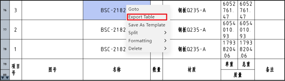
Usage Instructions:
1) Right-click at any position in the table.
2) Click the "Export Table" option.
3) In the pop-up dialog box, set the file format and filename.
4) Click OK to download the file to your local system.

Dialog Control Descriptions:
File Format: Used to select the file format for export. Supported formats include "xlsx, xls, txt, csv."
Filename: Used to set the name of the exported file.
# Geometric Tolerance
# Combined Type Frame
Supports combining frames of the same type of geometric tolerances.
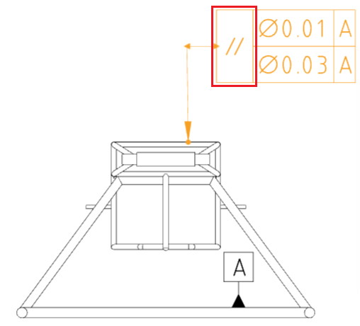
Usage Instructions:
1) Create the geometric tolerance symbols.
2) In the symbol pane, click the drop-down box for the type frame you wish to combine.
3) Select "Combine Above" or "Combine Below" from the pop-up menu to merge this frame with the frames above and below it.
4) Click the drop-down box again and select "Make Independent" to separate this frame from others.
5) Close the dialog box to complete the settings.
# Prefix and Suffix Text
Supports adding text before and after the geometric tolerance symbols.
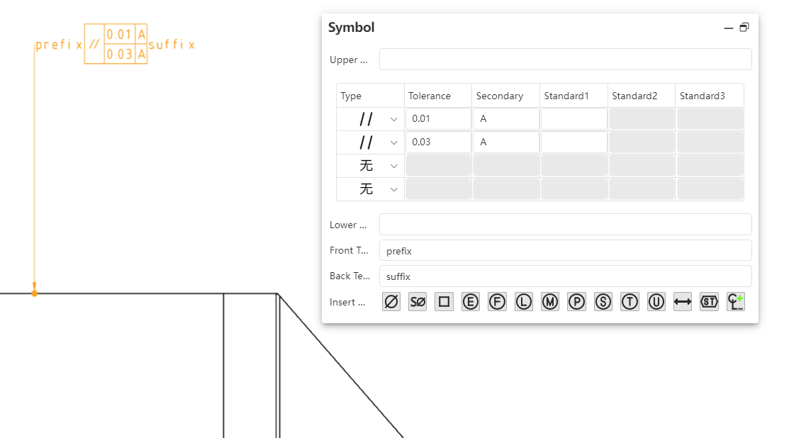
Usage Instructions:
1) Create the geometric tolerance symbols.
2) In the symbol pane, enter text in the "Prefix Text" and "Suffix Text" input fields.
3) The text will be displayed before and after the symbols, respectively.
4) Close the dialog box to complete the settings.
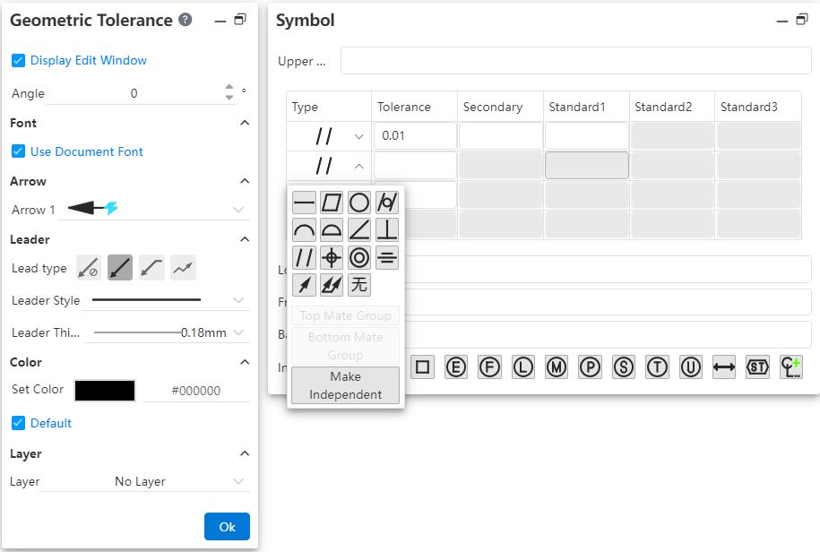
# Symbol Library
A new symbol library feature has been added, allowing the insertion of a wider variety of symbols.
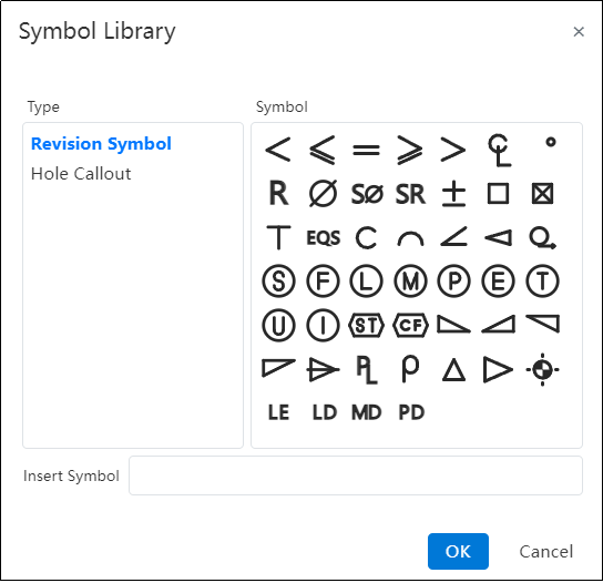
Usage Instructions:
1) Create the geometric tolerance symbols.
2) Click on the input field where you want to insert a symbol, ensuring the cursor is blinking within the field.
3) Click the last button in the "Insert Symbol" toolbar to open the symbol library.
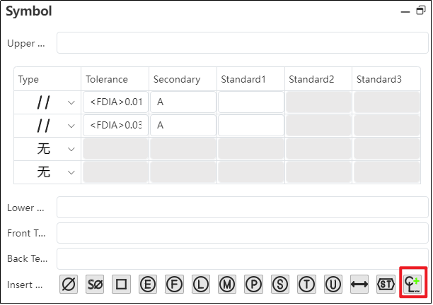
4) In the symbol library, click the desired symbol to be inserted.
5) Click “OK” to insert the selected symbol into the input field.
6) Close the dialog box to complete the settings.
# Frame Alignment
Optimize the frame alignment to ensure that frames remain aligned when entering the same number of digits, Chinese characters, or English letters in different frames. This results in a neater appearance on drawings.

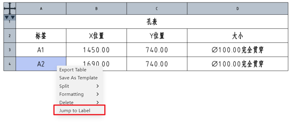
# Hole Table
# Quick Hole Location
By using the hole table, you can quickly confirm the position of a selected hole by right-clicking on the label and navigating directly to it.
# Simultaneous XY Axis Selection
Supports simultaneous selection of both the X-axis and Y-axis directions. The intersection of the X-axis and Y-axis is automatically set as the origin, and a hole table is generated.
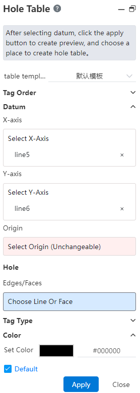
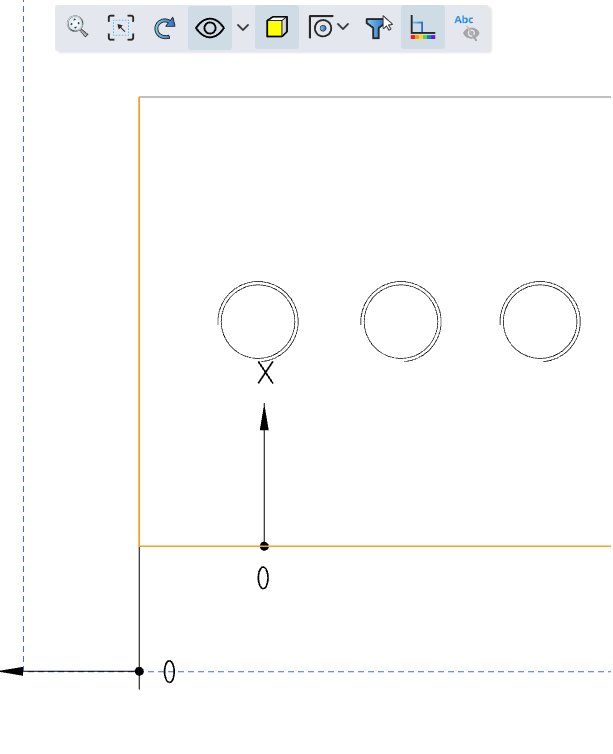
# Coordinate Direction Re-editing
The coordinate direction of the hole table supports re-editing, which facilitates modifying the direction definition of the hole table.
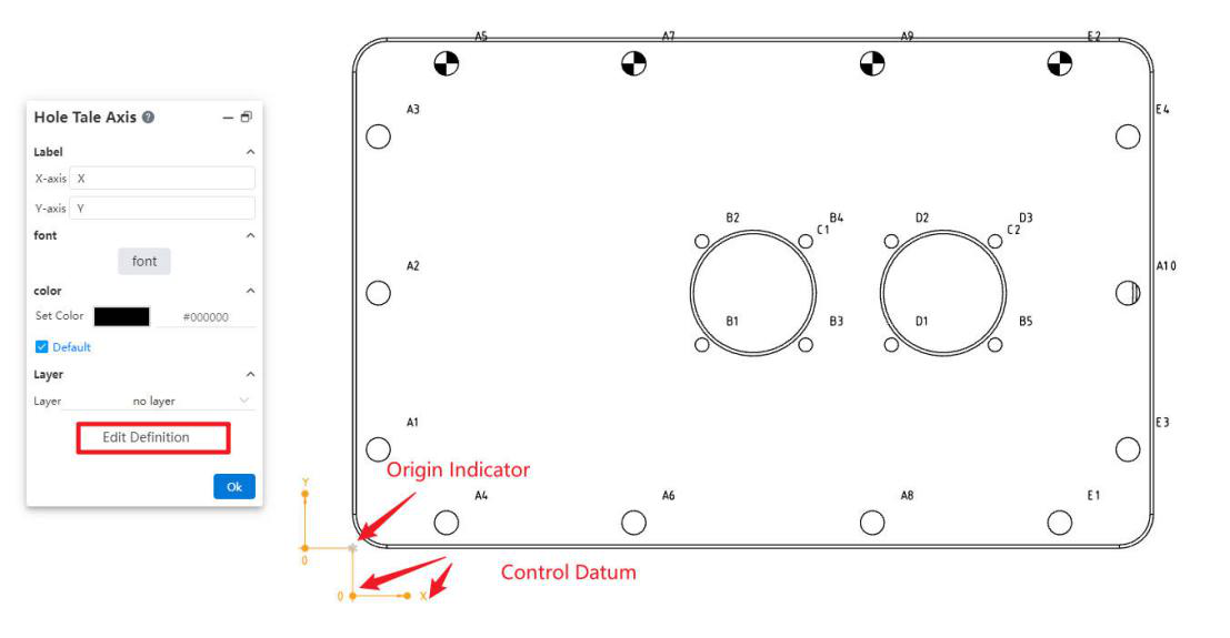
Select the origin indicator to open the "Hole Table Axis" dialog box. In this dialog, you can set the text and font for the X-axis and Y-axis annotations, as well as the associated layer.
Click the "Edit Reference Definition" button in the "Hole Table Axis" dialog box to redefine the coordinate system reference.
When an indicator is selected, dragging it allows you to reverse the X and Y directions. You can also modify the offset distance and direction of the arrow leader from the origin.
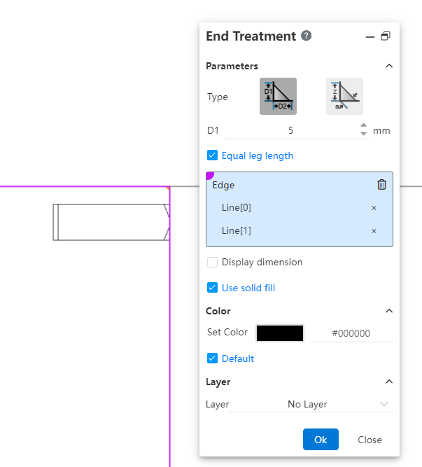
# End Treatment
A new end treatment command has been added to generate markers for annotating the cross-section of welds.
Usage Instructions:
1) Click the "End Treatment" command.
2) Select two intersecting edges.
3) Click in the viewport to generate the end treatment annotation.
Notes: If there are multiple intersection areas for the selected edges, the annotation will be generated where you click in the viewport.
Dialog Box Control Descriptions:
Type: Choose the type of endpoint symbol.
Size: Set the size of the endpoint symbol using parameters D1, D2, Z, and a according to the chosen type.
Equal Support Lengths: Check this box to set D1 = D2.
Edges: Select the two edges on either side of the endpoint symbol.
Show Size: Check this box to display the size dimensions of the endpoint symbol.
Solid Fill: Check this box to fill the interior of the endpoint symbol with a solid color.
Color, Layer: Control the color and layer for the endpoint symbol annotation.
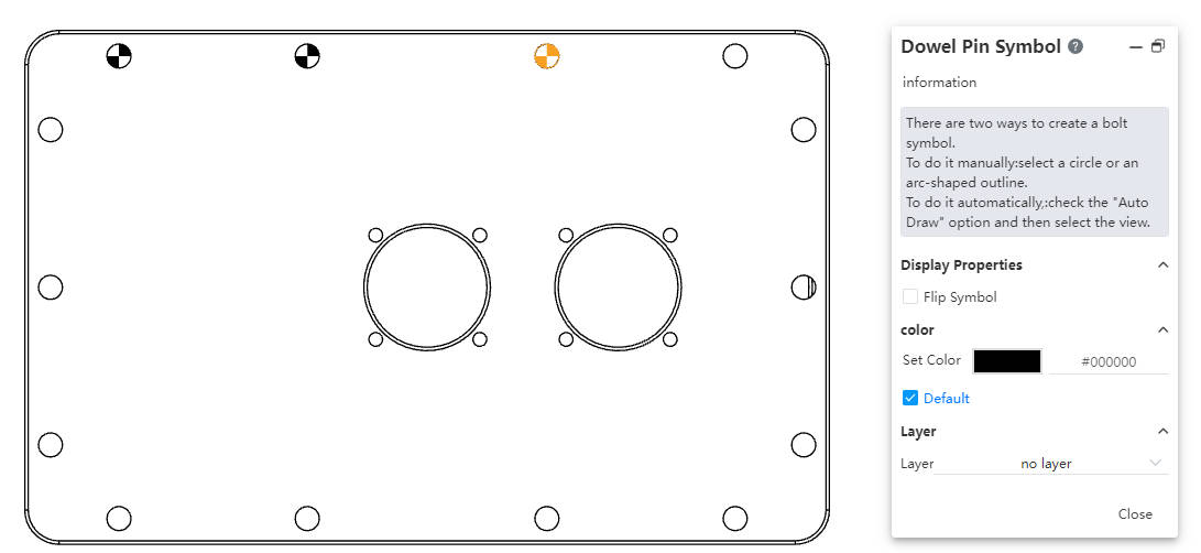
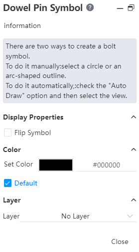
# Dowel Pin Symbol
A new function for adding dowel pin symbols has been added to annotate pins on circular holes.
Usage Instructions:
1) Click the dowel pin symbol  tool in the toolbar to open the command dialog box.
2) Set the color and layer.
3) Manual insertion:Pick the front view of a circle or an arc projection line/sketch line.
Automatic insertion:Check the option for all blind holes, then pick the view where
you want to create dowel pin symbols.
Notes:
Manual addition allows picking the same edge multiple times to add dowel pin symbols, while automatic addition does not allow adding symbols to edges that already have them.
Once manual insertion begins, it cannot be switched to automatic insertion in the current session. You need to restart the command to select the automatic option.
Pre-selection: Start the dowel pin symbol command after pre-selecting a circle or arc to directly enter the manual insertion process.
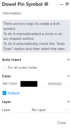
Dialog Box Control Descriptions:
For all blind holes: Check this option to enter automatic insertion mode.
Reverse symbol: Check this option to switch the filled color areas in the symbol (this option is displayed when a dowel pin symbol is selected).
Set color: Set the color for creating the dowel pin symbol.
Default: Check this option to create the dowel pin symbol with the default color.
Layer: Set the layer for the created dowel pin symbol.
# Sheet Metal
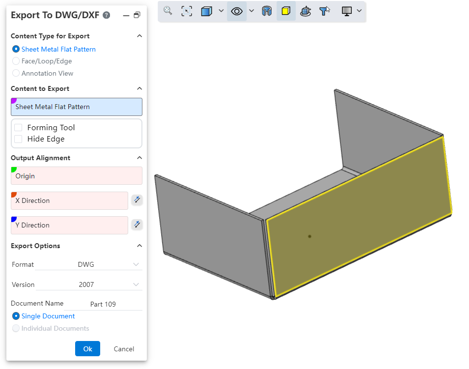
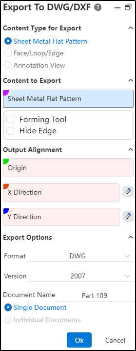
# Export To DWG/DXF
Added export to DWG/DXF functionality ,To easily one-click export engineering drawings with the outlines of sheet metal flat layout models.
Usage Method:
1) In the Import /Export dropdown menu,click on “Export to DWG/DXF ”.
2) Select the content type, content, alignment, file format, etc. to output.
3) Click OK, and a preview window will appear.
4) In the preview window, you can select the unwanted lines and click 'Delete' to remove them.
5) When exporting multiple contents, you can use the left and right buttons to switch between drawings.
6) In the preview window, click OK to complete the export.
Dialog Box Controls Guide:
Output Content Type: Used to select the type of content you want to output.
Sheet Metal Flattened Style: Outputs views of sheet metal in flattened style. This option is only available for sheet-metal parts. When there are multiple sheet metals, each can be output as a separate flattened view.
Faces/Rings/Edges: Select parallel faces or edges and project them onto the same plane to output as an engineering drawing.
Annotation View: Select one or more view directions to generate views of the selected directions.
Objects to Output: Depending on the selected output content type, choose the corresponding objects to output.
Output Alignment: Set the point in the model that will align with the origin of the engineering drawing and the XY direction. This is an optional setting.
Output Options: Control the file format, version, file name, and how multiple drawings are output。
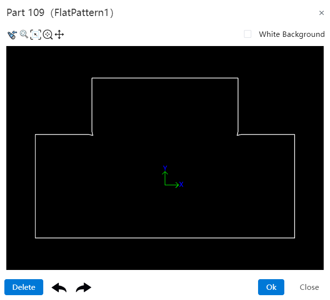
Dialog Box Controls Guide:
Buttons: From left to right, the buttons are "Previous Page、Previous View、Adaptive、Focus on Selected Area、Zoom、Pan、Next Page."
Previous Page: Click to switch to the previous page.
Previous View: Click this button to return to the previous view.
Adaptive: Same functionality as in the viewport (keeps the content centered and adjusts scale accordingly).
Focus on Selected Area: Same functionality as in the viewport (zooms into a selected area of the drawing).
Zoom: Click, then hold down the left mouse button and drag up or down. Dragging upward zooms in; dragging downward zooms out.
Pan: Click, then hold down the left mouse button to pan(move) the view horizontally or vertically.
Next Page: Click to switch to the next page.
White Background: When checked, this changes the background color of the preview viewport to white.
Delete: Select a line in the preview viewport and click this button to delete it.
Undo、Redo: Undo or redo the delete operation.
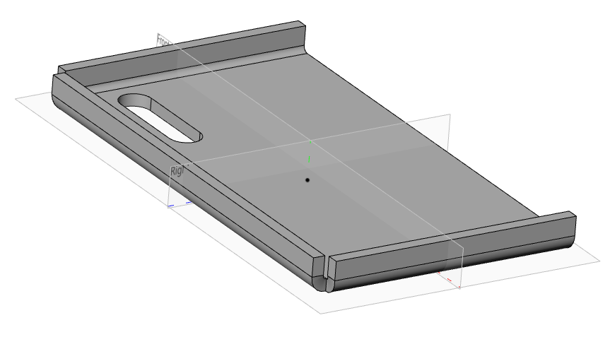
# Normal Cut
When stretching to remove a sheet metal part, adding an Normal Cut option allows for the quick creation of a model that conforms to the characteristics of sheet metal.
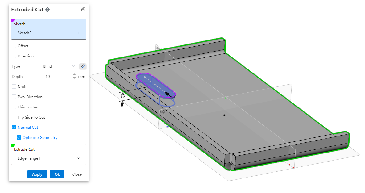
Usage Method:
1) Draw the removal sketch and sheet metal body.
2) Open the Stretch Remove command, select the sketch and sheet metal part.
3) Check the Normal Cut option.
4) Click OK to create a removal feature where the cutting surface is perpendicular to the sheet metal face.
Instructions:
The orthogonal removal option is only available when removing sheet metal parts.
Enabling "Optimize Geometry" will smoothly connect the top and bottom projections of the removed section, facilitating subsequent processing or operations.
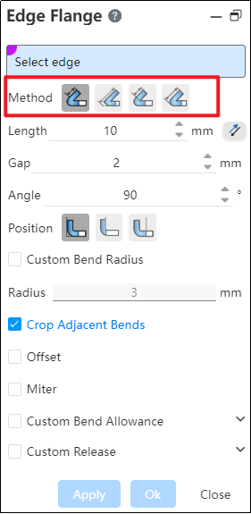
# Edge Flange
The Edge Flange command has been optimized for details. The system will now record the last used "Method". Next time you use the edge flange command, the "Method" will default to the item used in your previous session.
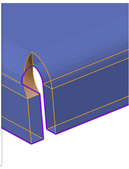
# Corner Relief
A new "Corner Relief" command has been added to handle sheet metal edges and corners.
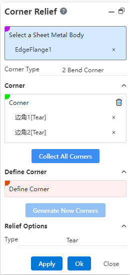
Usage Method:
1) Click the Corner Relief command.
2) Select the sheet metal entity whose corners you want to handle.
3) Click the "Collect All Corners" button, and all processable corners are automatically filled in.
4) Alternatively, pick the bend faces on both sides of the boundary within the "Define Boundaries" selection box, click "Generate New Corner," and manually select the corner that needs handling.
5) Click OK to finish the corner relief operation.
Dialog Box Controls Guide:
Select a Sheet Metal Body: Choose the sheet metal entity where you want to add corner reliefs.
Corner Type: Displays the types of corners that can be processed.
Corners: Shows the selected corners to be handled.
Collect All Corners: Click this button to automatically collect all processable corners on the sheet metal body.
Define Corner: Select the bend faces on both sides of the corner in this section, click "Generate New Corner," and manually add corners to be processed.
Generate New Corner: After selecting the bend faces, click this button to manually add a new corner for processing.
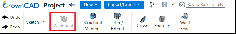
# Weldments
# Weldment
Add a weldment command,The addition of a weldment command allows ordinary part documents without welded structural components to become weldments, enhancing design flexibility and accommodating diverse engineering needs.
Usage Method:
1) Draw the necessary solids.
2) Click on the "Weldment" command.
3) The collection of solids in the Feature Panel changes to a "Cutting List," allowing you to view and configure cutting list attributes for each solid.
4) Proceed with generating engineering drawings, creating weldment cutting lists, and other subsequent operations.
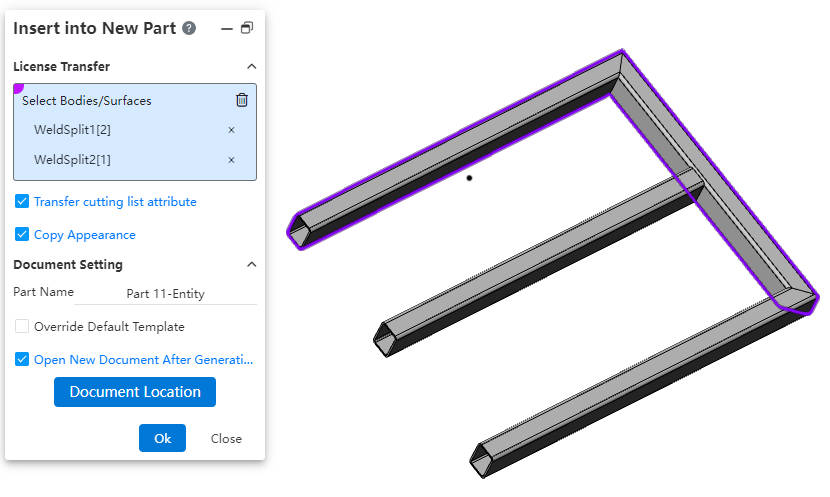
# Insert into New Part
Create the Feature "Insert into New Part",This function is designed to allow users to insert solids or surfaces from their current document into a newly created part, enabling them to perform additional operations within this new context.
Usage Method:
1) Right-click on the solid in the Feature Panel.
2) Select the "Insert into New Part" option from the context menu.
3) Choose the solids or surfaces you wish to insert into the new part.
4) Configure the transfer options as required.
5) Click OK, resulting in the creation of a new part with the selected solids or surfaces inserted.
Dialog Box Controls Guide:
Select Solids/Surfaces: Choose solids or surfaces you wish to transfer into the new part.
Transfer Cut List Properties: When 'weldment' features are present, enable this option to copy weldment cut list properties to the new document.
Copy Appearance Settings: Enabling this transfers appearance settings of selected geometry from the source document to the new one.
Part Name: Define the desired name for the newly created part.
Override Default Template Settings: Select an option if you wish to manually choose a different part template for the new document.
Open New Document After Creation: Enabling this will automatically open the new document once creation is complete.
Document Location: Use this button to specify where the new document will be saved via a dialog box.
IMPORTANT NOTE: The solids or surfaces in the newly created part document do not have an association with the source geometry.
# Data Translation
# Import
The system has been enhanced to support the following additional document formats during import:emp、emn、vda.
# Import- System Setting
Add a new setting under system configurations to enable the reading and extraction of coordinate points from design models created in various CAD systems, including Creo, NX (UG), CATIA, and SolidWorks. These extracted points can then be imported into the target system as "reference points" for alignment or other design purposes.
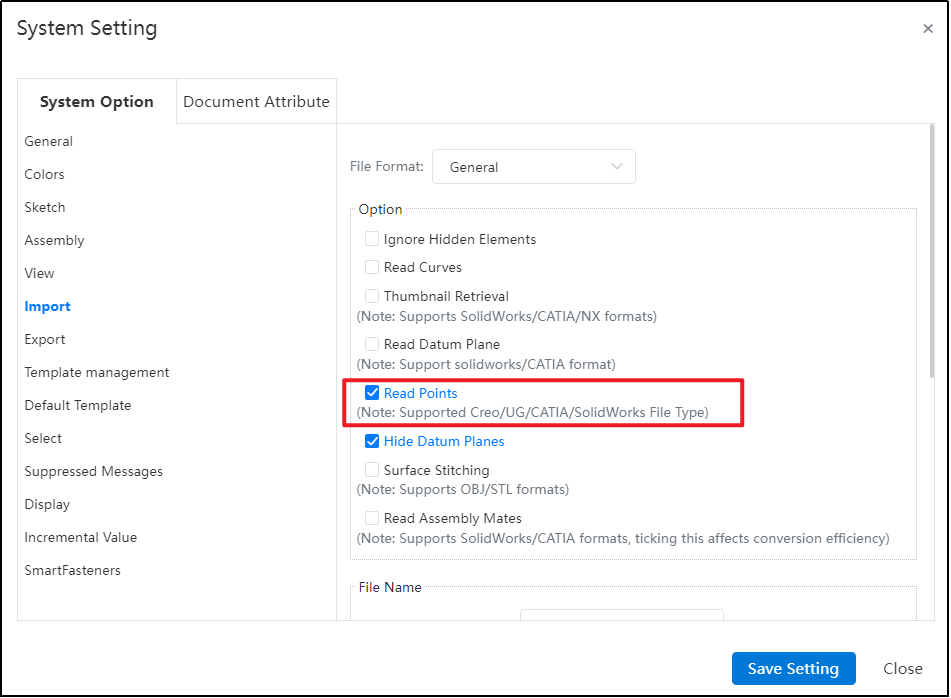
Note: The imported "points" function solely as references and cannot be edited once imported. These reference points are fixed within the system following importation and cannot undergo any further changes or modifications.
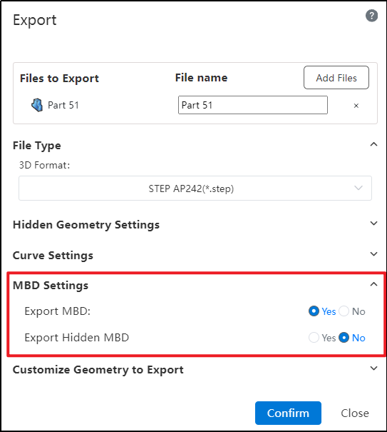
# Export stp242
Export added format 'STEP AP242 (*.step),During the export process, users now have the capability to determine whether MBD (Model Based Definition) information, including hidden MBD elements, should be included in the exported file. This feature provides greater control over the data output, facilitating precise and customized data exchange.
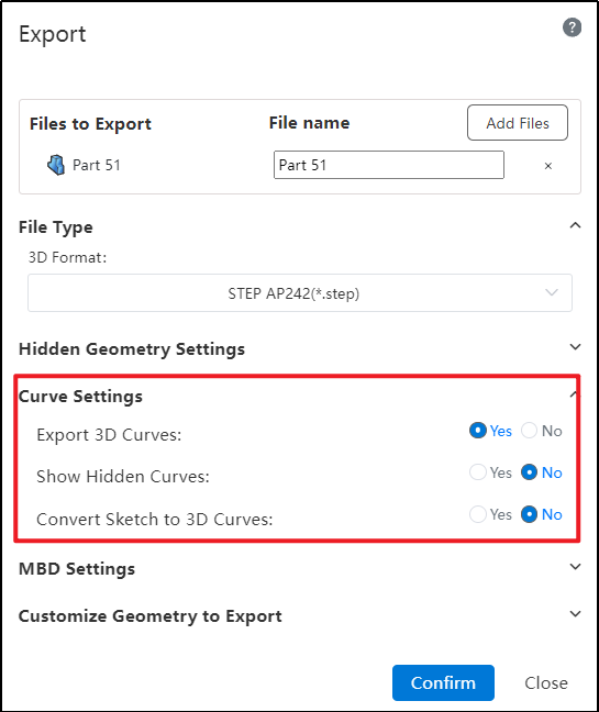
# Export Curves
The latest update introduces a new curve export functionality. This feature ensures you can simultaneously export curves along with your 3D model while providing the ability to set detailed parameters for these curves during the export process.
Dialog Box Controls Guide:
Exporting Spatial Curves: This setting allows you to determine whether spatial curves within a model are exported during the file export process. You can enable or disable this option based on your specific requirements.
Restoring Hidden Curves During Export: Hidden spatial curves, which are not visible in the model by default, can be converted to a displayed state when exporting. This feature lets you control whether these hidden curves should reappear in their original form once exported, ensuring that all relevant information is captured accurately.
Exporting Sketches as Spatial Curves: When dealing with sketches within your model, this control allows you to specify whether such sketches should be exported as spatial curves. Enabling this option means the sketch details will transfer over in the same manner as other spatial curves, preserving their geometric and associative properties for downstream applications.
Note:
Unsupported Curve Export Formats: Currently, the feature to export curves is not supported for files in the following formats: STL, OBJ, FBX, SLVX, and IFC.
Parasolid (x_b, x_t) Format Constraint: When exporting using the Parasolid format (extensions .x_b or .x_t), it is mandatory to select the option "Restore Hidden Spatial Curves to Displayed State". This ensures that hidden curves are made visible during the export process.
**IGES Export Behavior:**For Solid/Surface exports, hidden elements remain in their hidden state but are still exported;When exporting Components (Parts), hidden components will not be included in the output file.
Sketch Conversion for Spatial Curve Export: Conversion and export of sketches to spatial curves is only supported when the sketch is currently in its displayed (visible) state. Hidden or unselected sketches cannot be exported as curves under this feature.
# Export Rename
Added a new feature to rename files during export.
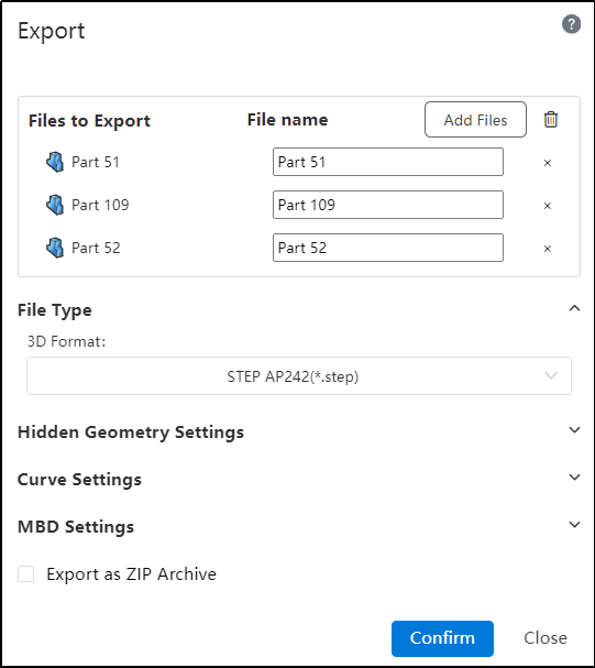
Usage Method:
1) Select the file you want to export.
2) Click on the text box below the filename and enter a new name.
3) Click "Confirm" to export the document with the custom name.
# MBD
# View Orientation
In the assembly, view orientation functionality has been added, and drawings can select this oriented view projection.
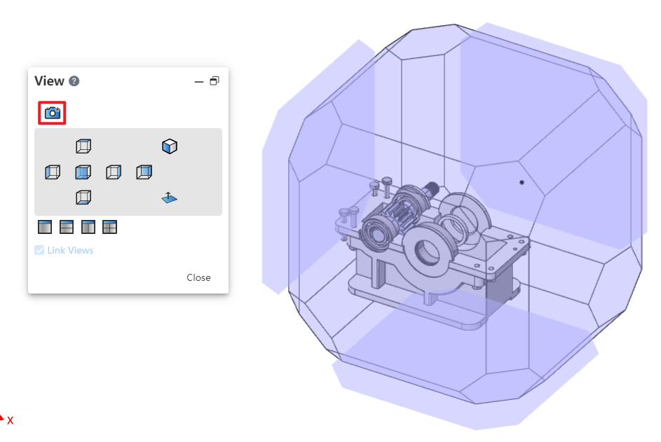
Description:
In the Top-down environment, the assembly's custom views are still displayed, and newly created views belong to the assembly rather than the current parts or sub-assemblies you're editing.
# Settings
# Document Properties
# Leader Style
In the drawing system settings - document properties, a new leader type has been added, which supports defining distinct leader styles for different edge types, including specifications such as edge type and line thickness.
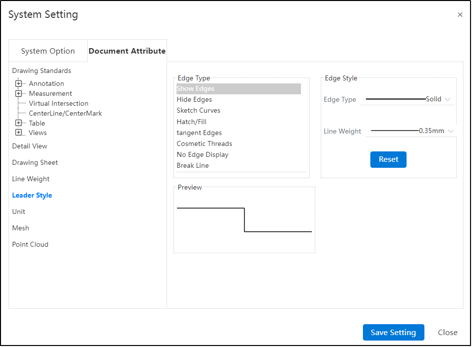
Description:
Hatch/Fill only allow the setting of line width and do not support defining leader styles.
In drawings, sketch line thickness are not preserved in color schemes.
# Line Weight
In the drawing system settings - document properties,a new line thickness option has been added, allowing users to manage and adjust line thickness effectively.
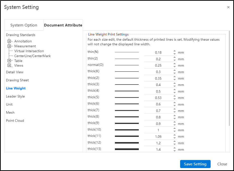
Description:
Only drawings allow access to these setting configurations; in part and assembly environments, the line thickness configuration page is unavailable, restricting users to default settings without the ability for customization.
Upon exporting or printing with adjusted line thicknesses, some software and hardware may not support custom-defined widths, automatically adjusting them to the nearest available standard width instead.
# Display Modes
In the system settings, additional display modes-related configurations have been introduced, allowing users to navigate between these settings and color preferences seamlessly.
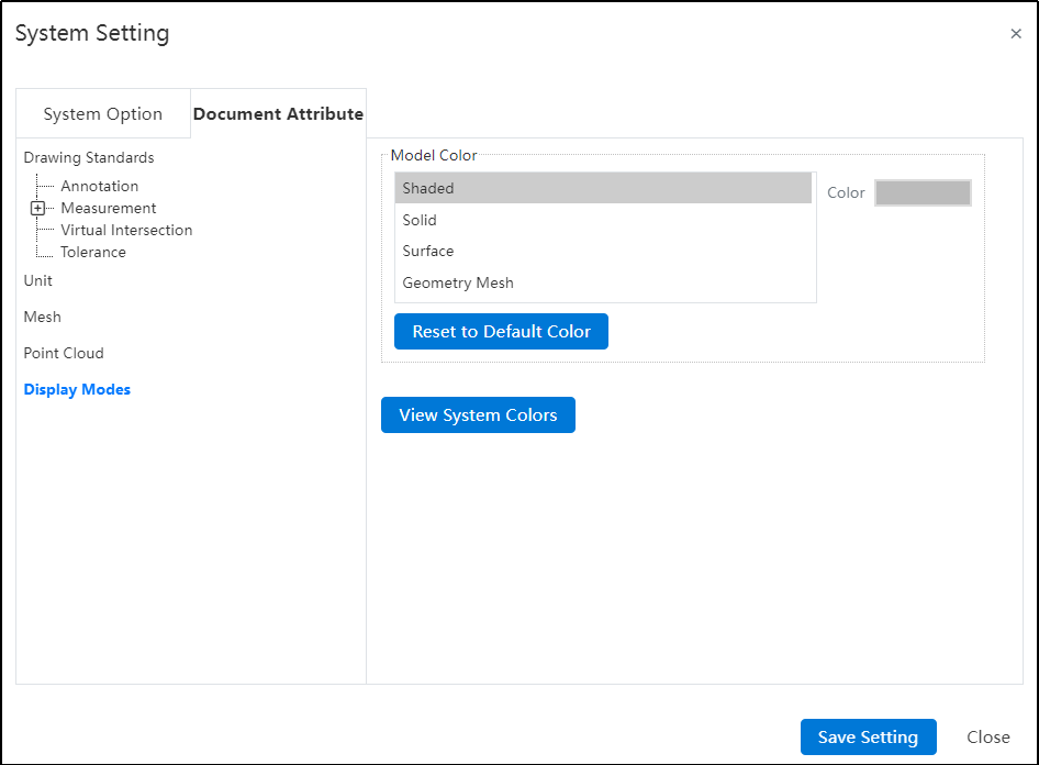
Control Parts Description:
Shaded: Manages the default visual appearance of parts, maintaining bidirectional synchronization with the "Appearance Settings" under the "Parts" category.
Geometry-Entities/Surfaces/Meshes:Controls the visual presentation of corresponding geometry elements (solids, surfaces, or meshes). This option is only available within part-level documentation.
Reset Colors to Defaults: Clicking this button restores all color settings to their original default values.
View System Colors: Click "View System Colors" to navigate to the system-wide color configuration interface located under "System Settings > System Options > Colors."
# Sketch
In the System Settings-System Options-Sketch section, a new feature has been added:"Automatically Rotate View Perpendicular to Sketch Plane During Creation and Editing."
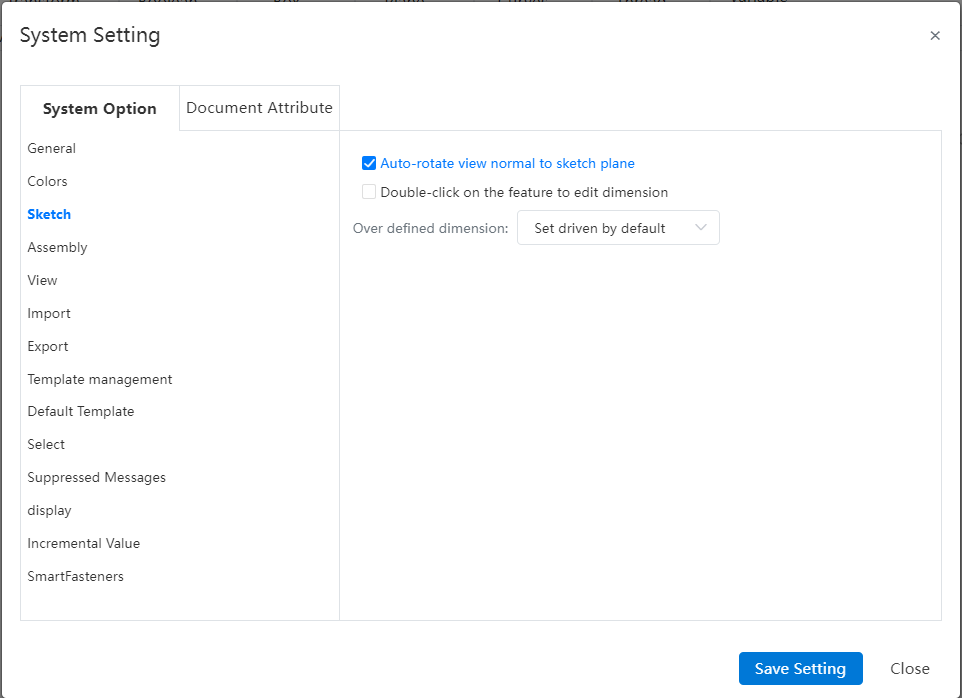
Description:
- Enabling this feature ensures the viewing angle automatically aligns perpendicular to the sketch reference plane during both sketch creation and editing processes.
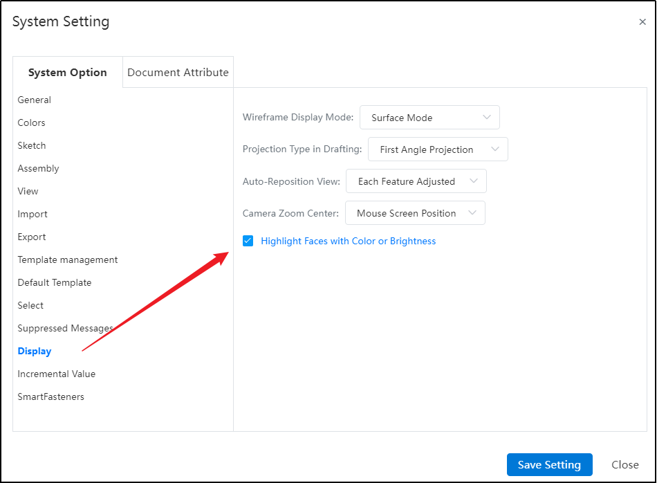
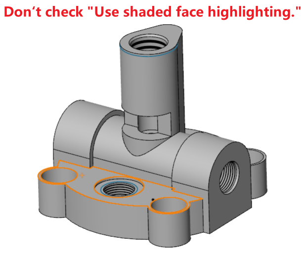
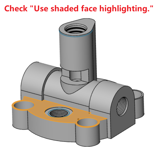
# Show
In Show Settings, introduce a checkbox named 'Use Shaded Face Highlighting' to control whether the entire selected face is highlighted.
# Select
Improve the user experience for the “Launch Through Transparent Face Selection”option by enabling the Shift key to temporarily toggle its functionality during element selection.
Description:
Without holding Shift while selecting elements, it has the same effect as the current selection state.
If currently selected, holding Shift while picking an element deselects this option.
If currently deselected, holding Shift while picking an element selects this option.
# Color
System Settings - Colors - Drawing Colors now includes additional color type options that can be set.
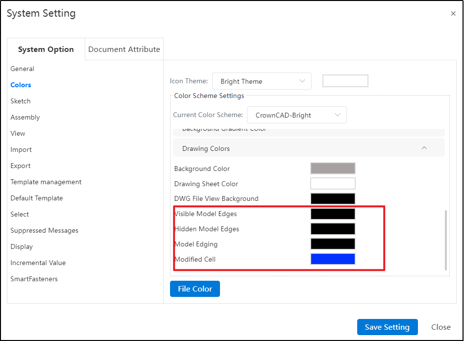
Description:
The drawing colors set in System Settings can be applied through the color - "Default" option in the "Line Type" command.
Color settings related to "Drawings" only take effect within Drawing documents.
# Library
# Sketch Library
The enhanced feature allows new drawings to reference content from a sketch library, enabling the insertion of sketches saved in the knowledge base into drawings and various views that support adding sketches.
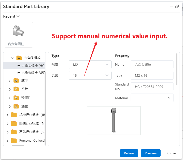
# Standard Components Library
The enhanced standard compoents library functionality in assembly design now supports defining the custom length of a standard compoents when inserting it into an assembly.
# Rendering
# Section View
Optimization of Render Effects for Sectional Views.When 【Display Cutaway Cap】 is checked and 【Preserve Cover Color】 is unchecked, the cutaway surfaces exhibit the actual colors of the components.
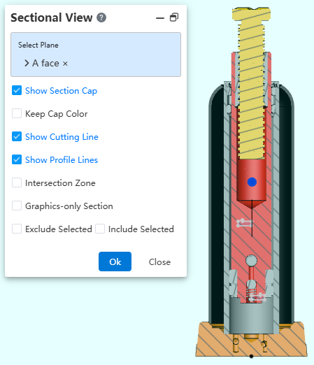
Description:
Part Visualization Priority:Entity Appearance > Part Visualization > Face Display;When only Face Display is applied, the cutaway faces reflect the entity's default color.
Assembly Visualization Hierarchy:Component Appearance Settings > Document-level Settings;Corresponds to "Application to Components" > "Application to Documentation".
# Project Document
# Project Management
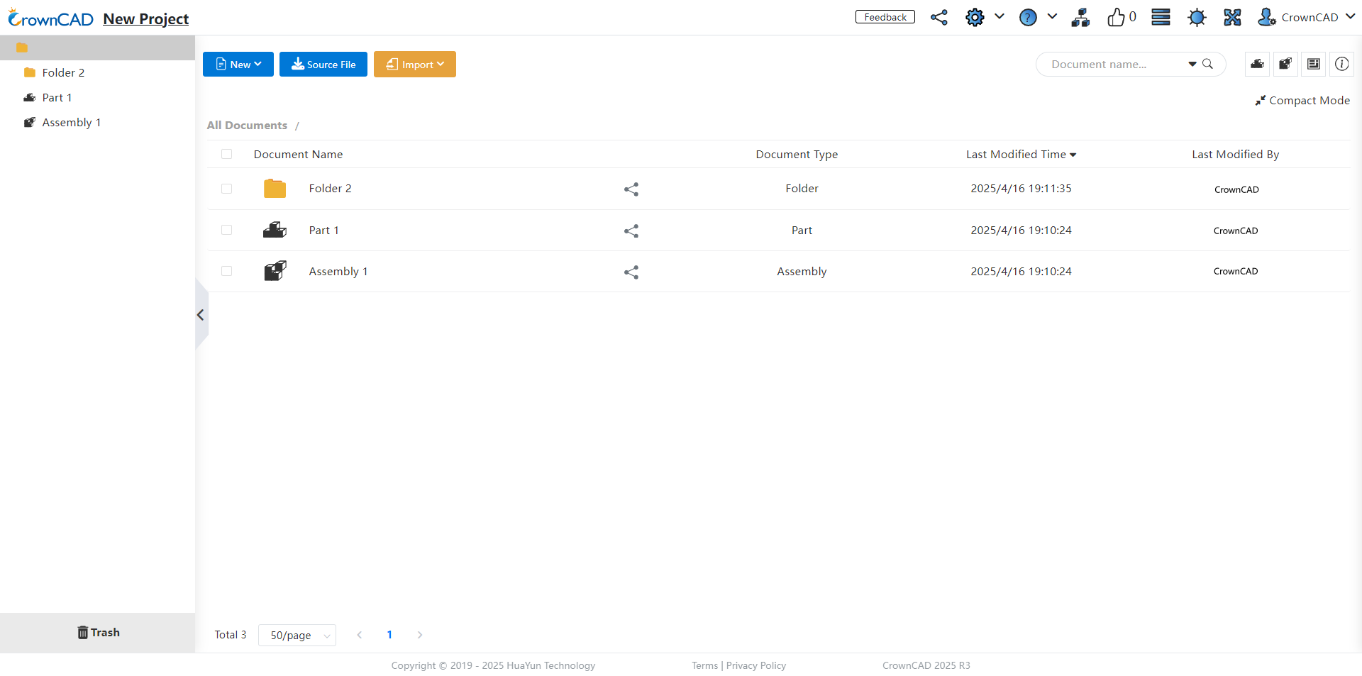
Optimized project management supports drag-and-drop functionality for moving projects and folders within the 'My Projects, Teams' section. Additionally, it supports setting the arrangement of lists in any project or document list. These settings should be recorded within the account; refreshes or closures of the browser page should preserve the arranged settings.
# User Manual
Optimized user manual, after enabling help, changing commands won’t always open a new tab; it will update the positioning to the first tab by default.
# Transfer Ownership
Transfer ownership of a newly added folder entirely and maintain its file structure.
Description:
You can only transfer ownership of your own folders.
Ownership of team folders is transferable exclusively by the team creator.
# Collaborative
# Activity
Optimized the activity module to make event management more convenient and orderly.
# Create Activity
Optimized the activity creation function and added a participant information statistics feature.
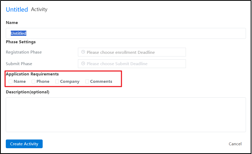
Instructions:
1) Click the 'Activity ' icon in the upper right corner to enter the activity management page.
2) When creating an activity, add checkboxes for 'Name', 'Phone', 'Organization', and 'Remarks'.
3) After selecting these options, they will be mandatory fields for participants when registering. If any required field is incomplete or incorrect, a corresponding alert will be displayed.
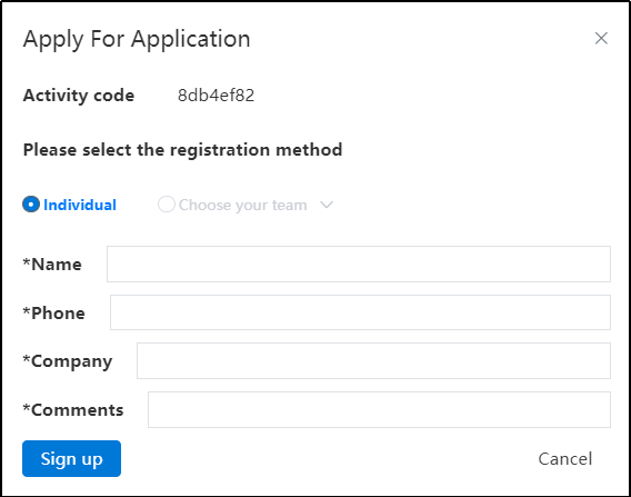
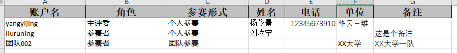
4) When the activity creator exports the participant list, based on the selected checkboxes, include the corresponding details such as name, phone number, organization, and remarks.
# Join the Activity
Add a restriction feature to prevent a user from participating in multiple forms, ensuring fair competition.
Description:
Participants can choose to compete either individually or as part of a team, but not both. If a user has already participated as an individual, the team(s) they are part of cannot join the same activity. Conversely, if a user joins through a team, they cannot participate in the same event individually.
If a user is a member of multiple teams and one team has joined the activity, all other teams that the user belongs to will be unable to register for that same activity.
Once User A has joined an activity as part of a team, they will be unable to join the same event again using any other method, such as importing a list.
# Submission Folder
Added a new feature to submit works via folders, optimized the status display after personal/team folders are shared to activity modules, and added control measures to further improve the submission process.
Description:
After a participant shares the folder to the activity, they can still make edits. Once it is manually submitted or the submission deadline is reached, the folder will be archived, and all projects and documents within it will also be set to archive mode, preventing any further editing.
After the folder is submitted, clicking on the project name in the upper-left corner for individual/team projects no longer displays project settings. For team creators, right-clicking an internal project does not show any project permission commands in the options.
# Teams
# Labels
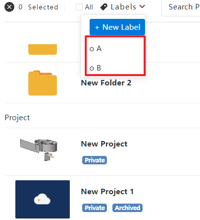
Added a label-functionality for intra-team created projects. Simultaneously, users can now conveniently filter and quickly locate specific projects through tag screening.

Instructions:
1) Team members can add descriptive labels to their projects by selecting the "Labeling" option from the right-click menu of intra-team projects. This feature aids in managing and organizing projects by applying relevant tags.
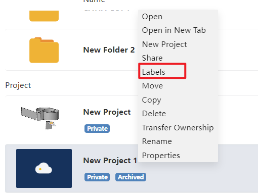
2) The "Labels" dropdown provides users with a clear view of all team-based project tags, allowing efficient search and filtering according to applied identifiers.
# Project Management
The system has enhanced multi-level permission management, enabling more efficient and precise control over projects and folders in multi-selection scenarios for various roles.
Optimize the control of projects/folders in multi-select scenarios for different roles.
Team Creator Right-Click Permissions:
Single/multi-select right-click on projects created within the team: Tag, Move, Copy, Team Copy, Delete, Transfer Ownership.
Single/multi-select right-click on folders/projects created within the team: Move, Copy, Team Copy, Delete, TransferOwnership.
Single/multi-select right-click on shared projects/folders (all document owners are the user themselves, the team creator): Copy, Team Copy, Cancel, Delete.
Multi-select for both team-created and self-shared projects/folders by the team creator: Copy, Team Copy, Delete.
Multi-select for both team-created and others' shared projects/files (managed or members) in the team: Copy, Team Copy.
Multi-select for both own and others' shared projects/folders (or all are others' shares): Copy, Team Copy, Cancel.
Team Manager Right-Click Permissions:
Single/multi-select right-click on projects created within the team: Tag, Move, Copy, Team Copy, Delete.
Single/multi-select right-click on folders/projects created within the team: Move, Copy, Team Copy, Delete.
Single/multi-select right-click on shared projects/folders (all document owners are the user themselves, the team creator): Copy, Team Copy, Delete.
Multi-select for both team-created and self-shared projects/folders by the team creator: Copy, Team Copy, Delete.
Multi-select for both team-created and others' shared projects/files (managed or members) in the team: Copy, Team Copy.
Multi-select for both own and others' shared projects/folders (or all are others' shares): Copy, Team Copy.
Team Member Right-Click Permissions:
Single/multi-select right-click on projects created within the team: Tag, Copy.
Single/multi-select right-click on folders/projects created within the team: Copy.
Single/multi-select right-click on shared projects/folders (all document owners are themselves): Copy, Delete.
Multi-select for both team-created and self-shared projects/folders by the team creator: Copy.
Multi-select for both team-created and others' shared projects/files (managed or members) in the team: Copy.
Multi-select for both own and others' shared projects/folders (or all are others' shares): Copy.
# Properties
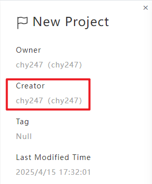
New capability to view project creator info for personal and team projects aids enhanced project administration.
Instructions:
Upon selecting "Details" after right-clicking a team project/folder, creators' names appear as "AccountName (Nickname).
# Delete team
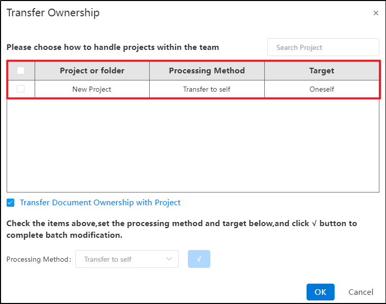
Team project ownership transfers include their top-level folders’ ownership.
Instructions:
1) When a team owner deletes the team through the Team Management Interface, an "Ownership of Team Projects" prompt appears.
2) Select the top-level folders displayed in this interface.
3) After confirming, all projects and subfolders within these top-level folders are transferred together with them.
Description:
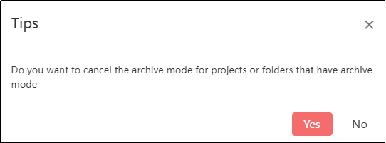
- When deleting a team, if there are projects or folders in archived mode that have not been submitted to the active status, a dialog box will appear asking: “There are projects/folders in archived mode. Do you want to cancel the archived mode?”Clicking "Yes" will automatically cancel the archived mode and redirect to the "Team Project Transfer Ownership Dialog Box".Clicking "No" will return to the team management interface, preventing the deletion of the team.
- When deleting a team, if there are projects or folders in archived mode and submitted to the active status, a dialog box will prompt: “There are projects/folders in archived mode. Do you want to cancel the archived mode?”.Clicking "Yes" will continue displaying a warning: “Existing projects/folders have been submitted to the active status, making it impossible to cancel the archived mode.”Regardless of clicking "OK" or closing the dialog box with "X", it will redirect back to the team management interface and prevent the deletion of the team.
