# Welcome to CrownCAD 2025 R4
Welcome to CrownCAD 2025 R4, which extensively incorporates the most genuine feedback from users and strives to meet customer needs to the greatest extent. In terms of usability, we are committed to enhancing your experience; in terms of functionality, we continuously add commands that you urgently need, helping you quickly complete product design and R&D work.
Key Enhancements:
| Sketch | Optimize the “Points on Curve” Icon. |
| Added a shortcut key for annotation, enabling quick switching between circle and arc dimension annotations under specific conditions. | |
| Feature | Enhanced Custom Hole Wizard Command and Optimized Hole Position Interaction.Support setting the same depth for threaded hole removal as the hole depth; allow adding a remote tapered hole for fully through threaded holes; and add optional specifications for threaded holes. |
| Assembly | Added document mating error prompts, which can indicate existing mating errors in the current mating within the assembly document and are displayed in a list format. |
| Support adjusting the hierarchy of components in the instance tree via drag and drop without entering sub-assembly edit mode. | |
| Support selecting multiple components while unloading or reloading. | |
| Drawing | Add new methods for creating cross-sectional views, supporting the use of drawn view sketches as cutting lines. |
| Data Translation | Supports importing CATIA drawing files and reading file headers, annotations, and drawing formats, among other contents. |
| Export document now includes new options: “Export Hidden Entities/Surfaces”and “Export Hidden Components”. These options allow users to control whether hidden entities, surfaces, or components are exported. | |
| MBD | MBD dimension annotation functions now include increased types of tolerances, offering more options for dimension tolerance annotations. |
| BOM | Added a new feature for blank size calculation, allowing users to perform blank calculations in custom properties, guiding blank preparation before part processing. |
| Settings | Added a new feature to highlight the edges of selected features in the graphical area, enabling control over whether the edges of selected faces and their related features are highlighted during face selection. |
| Custom - Keyboard settings now allow custom shortcuts for editing features and sketches. | |
| Added an image quality setting feature, supporting quality settings for document model display. | |
| AI | Added an intelligent command assistant feature that predicts the next command a user might need, while understanding the user's usage flow to further enhance the user experience. |
# Sketch
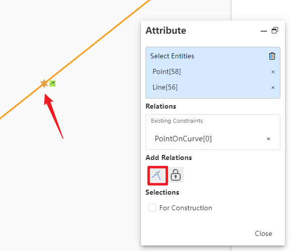
# Point On Curve
Optimize the “Points on Curve” Icon
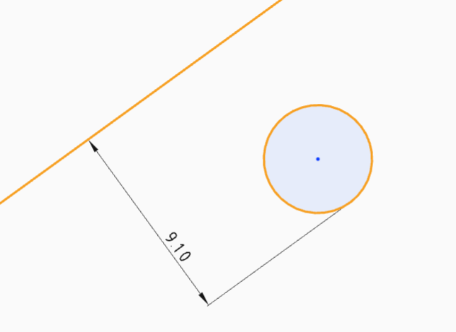
# Dimension
A new keyboard shortcut has been added to switch between circle/arc dimension annotation settings.
How to use:
1) Enter the sketch.
2) Activate the dimensional command.
3) Hold down the Shift key while clicking on the semi-circular contour range or center position where the maximum/minimum dimensional points of the circle/arc are located to quickly and continuously annotate the maximum/minimum or midpoint dimensions of the circle/arc.
# Parts and Features
# Hole Wizard
Enhanced non-standard hole wizard command with optimized hole position interaction, expanded design scenarios, and improved design efficiency.
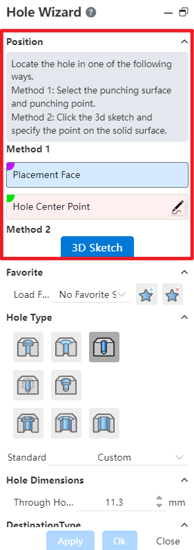
Function Description:
1) Added an "Equal to the Termination Depth" option for threaded holes, enabling the removal of threads to a depth equal to the hole's termination depth when specified.
2) Fully penetrated thread removal holes now support the addition of a remote taper hole.
3) Expanded the adjustable range for screw hole specifications and the depth of bottom screw holes.
# Assembly
# Mate
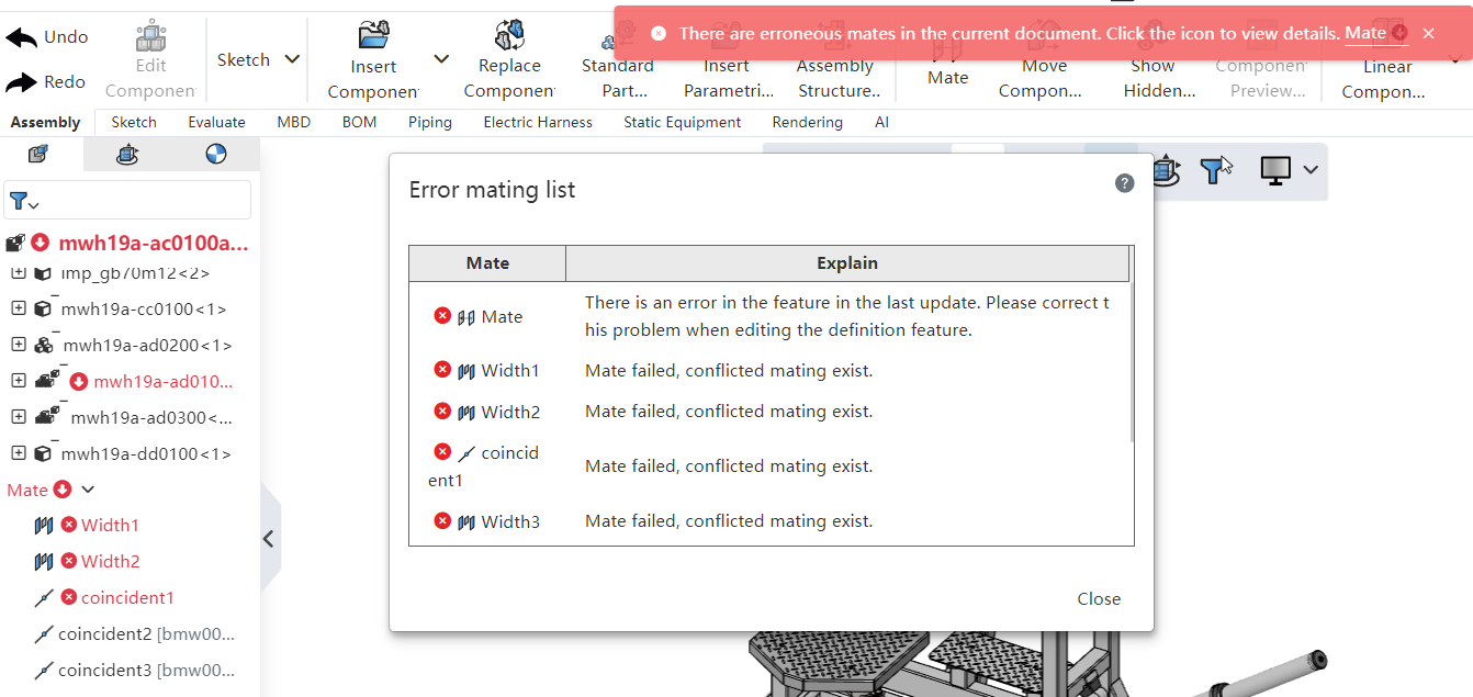
The assembly document alerts the user to current mating errors and presents them in a list format.
How to use:
1) Open the assembly documentation. When an incorrect fit is detected in the document, a error prompt message pops up.
2) Click the  icon in the error prompt to open the list of error fits.
3) Click to close this list.
4) Clicking the error symbol after the name of the fit list will again pop up the list of error fits.
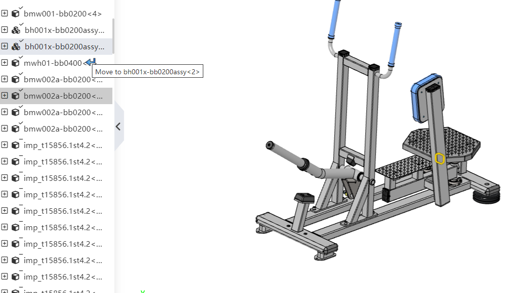
# Modify the component structure by dragging the instance tree
Support adjusting the hierarchical structure of components in the instance tree without entering sub-assembly editing mode by dragging and reorganizing the components.
# Unload/Reload
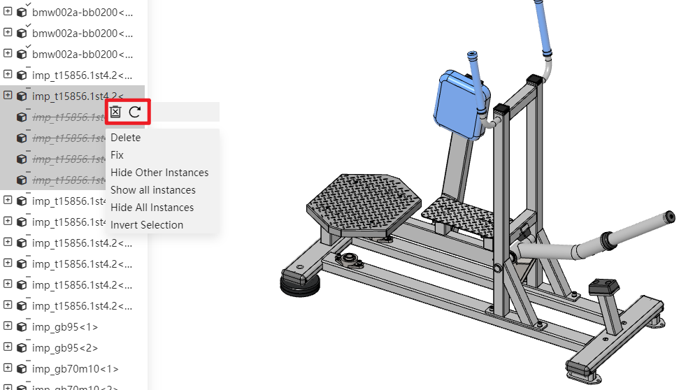
The system supports selecting multiple components to simultaneously unload or reload, effectively reducing repetitive operations and improving design efficiency.
How to use:
1) Select multiple components in the instance tree by holding down the Ctrl key.
2) Right-click to select 'Unload/Reload'(this option is only visible when there are components to unload in the selection).
3) All selected components will be unloaded/reloaded.
# Drawing
# Section View
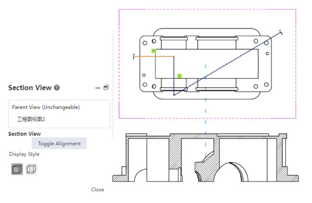
Add the new sketching feature for creating cross-sectional views, providing a more flexible way to create section views.
How to use:
1) Double-click the view to focus.
2) Draw a sketch in the view as the cutting line.
3) Select the drawn sketch.
4) Activate the section view command.
5) If the sketch consists of multiple lines, you can click to switch alignment and change the cutting direction.
6) Click on the blank area of the drawing sheet to place the section view.
# Data Translation
# Import CATIA Drawing
Support importing CATIA drawing files and reading file structure, annotations, and drawing format details.
# Whether or Not Export Hidden Components
The export document adds options "Export Hidden Entities/Surfaces" and "Export Hidden Components", supporting control over whether to export hidden entities, surfaces, and components via these options.
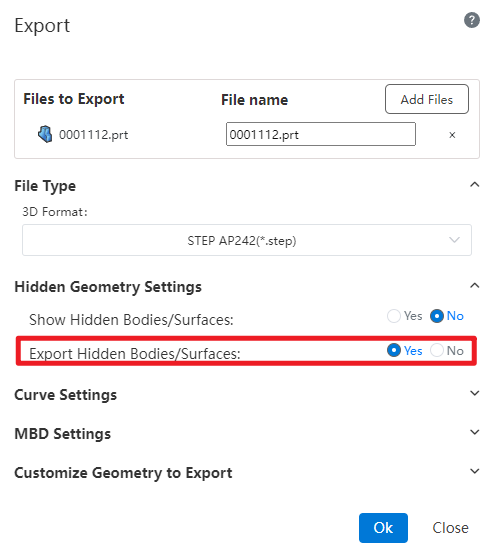
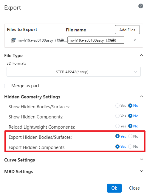
Note: This option is only visible when the hidden entities/surfaces/components are not restored to display state.
# MBD
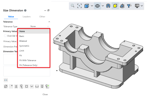
# Dimension
In MBD, dimension annotation functions now include additional tolerance types, offering users more options for tolerance dimension annotations.
# BOM
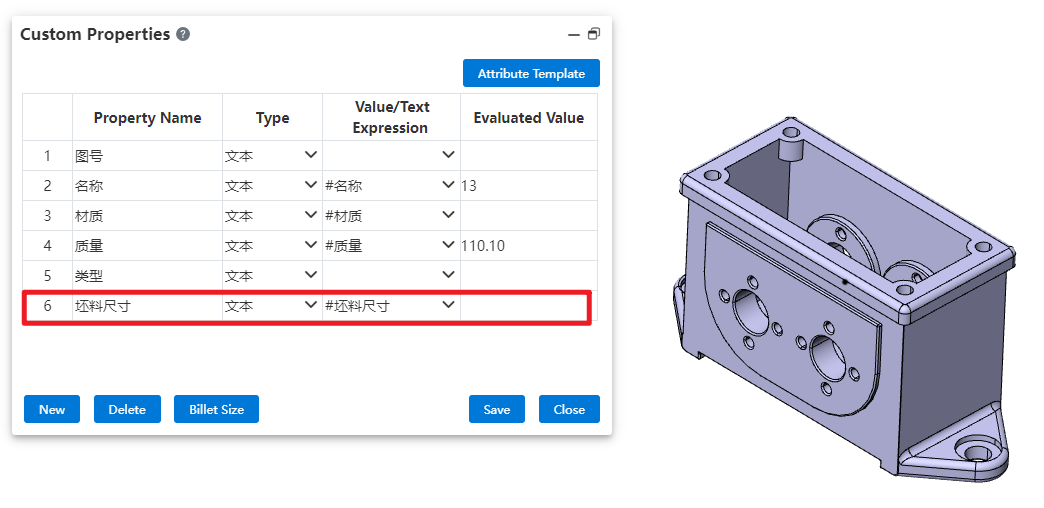
# Custom Properties
Added custom properties for blank size and blank calculation, which help guide the preparation of blanks before part processing.
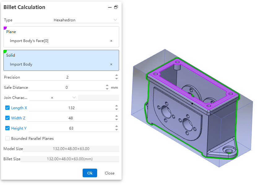
Control Description:
Type:Select the type of blank material, which can be either a hexahedron or a cylinder. Different types have different parameter items.
Plane:Choose the reference plane for creating the blank, which can be a solid plane, a curved plane, or a datum plane.
Precision:Control the display precision of the blank dimensions. You can manually input a number, adjust it using the mouse wheel, use increment/decrement keys, or enter a mathematical expression. Variables are supported.
Safety Distance:Adjust the amount added to the outer contour of the blank. The default value is zero, and both positive and negative values can be set.
Connection Character:Set the symbol used to connect the dimensions of the blank. Four types are provided, with the default being "×". You can choose from "×", "*", "-", or directly input any character.
Length/Width/Height:By default, these dimensions are automatically calculated based on the safety distance. You can manually input values, but after manual input, the safety distance will recalculate and revert to the automatically calculated values.
Bounded Parallel Plane:Control whether to create a parallel plane for the reference plane of the blank. If selected, the safety distance cannot be set, and the input fields for length, width, and height will be grayed out, preventing manual input.
Model Dimensions:Display the dimension parameters of the selected model after picking a plane or solid.
Blank Dimensions:Display the dimensions of the blank after the parameters are set.
How to use:
1) Click on BOM - Custom Properties to start the command.
2) In the numerical/text expression dropdown menu of any row, choose Blank Dimensions to display the current blank dimensions in the evaluated value field.
3) Click the Blank Dimensions button to begin the blank calculation process.
4) Select the type of blank calculation required
5) Choose the reference plane and relevant entities within the part for blank creation.
6) Adjust the display precision settings to control how blank dimensions are shown.
7) Specify the addition amount for the blank's outer contour.
8) Set the connection symbol used between blank dimensions (e.g., "×", "*", or "-").
9) Manually input or utilize automatically calculated values for length/width/height.
10) Determine whether to create a bounded parallel plane for the reference.
11) Click OK to complete the blank calculation. The new dimensions will be populated into the evaluated value field.
# Setting
# Display
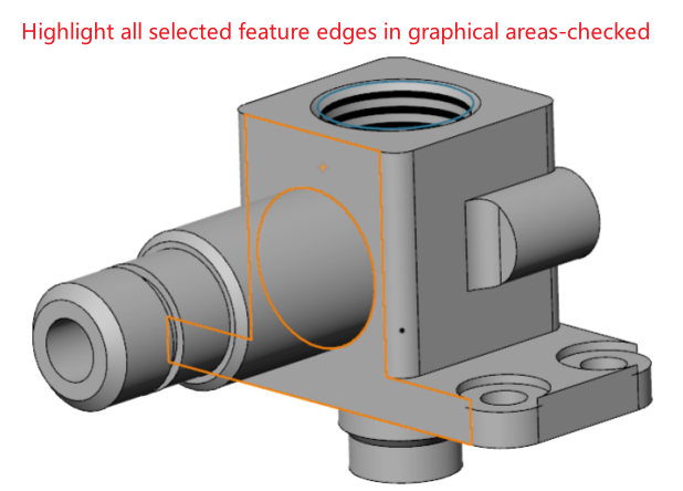
A new feature has been added to highlight the edges of all selected features in the graphical interface. Users can control whether selecting a face will also highlight the edges of its associated features.
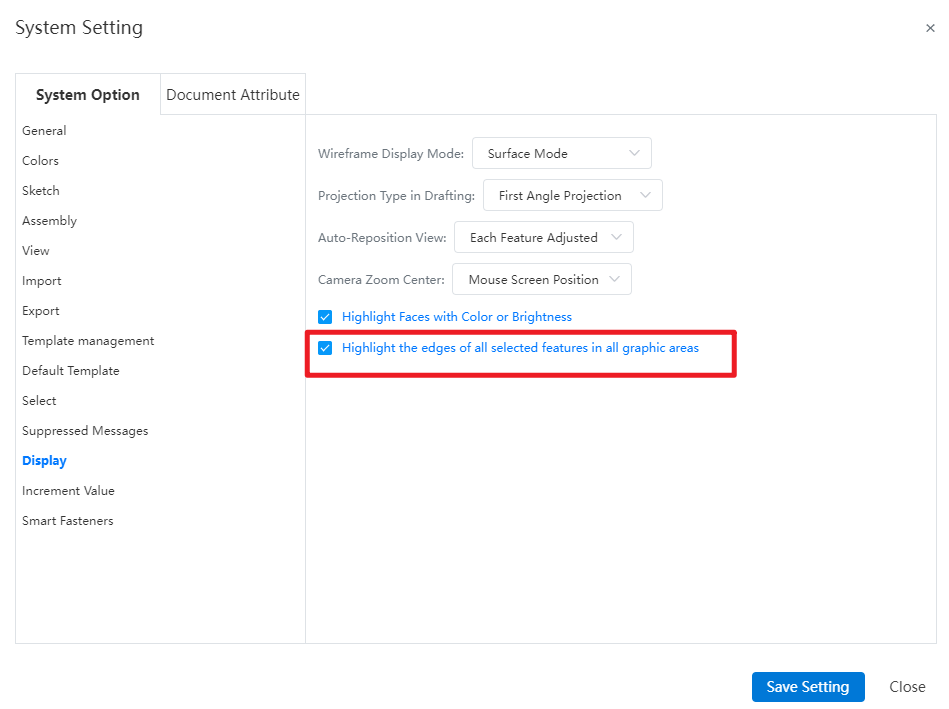
Note:
- Checked, when selecting a face, both the face and the edges of the associated feature are highlighted in the viewport. Unchecked, when selecting a face, only the face is highlighted in the viewport, and the edges of the associated feature are not highlighted.

# Customize-Keyboard
Under the “Customize - Keyboard - Edit”menu, add the “Edit Feature”and “Edit Sketch”commands, supporting the customization of shortcuts for these functionalities.

How to use:
1) Under Customize - Keyboard - Editing, customize shortcuts for editing features and editing sketch commands.
2) Select the feature/sketch name or element in the Feature Panel or viewport.
3) Click the customized shortcut key to automatically enter the corresponding editing state for the selected feature or sketch.
# Image Quality
Added image quality setting functionality, supporting the configuration of model display quality, which impacts sub-pixel display, file size, and performance.
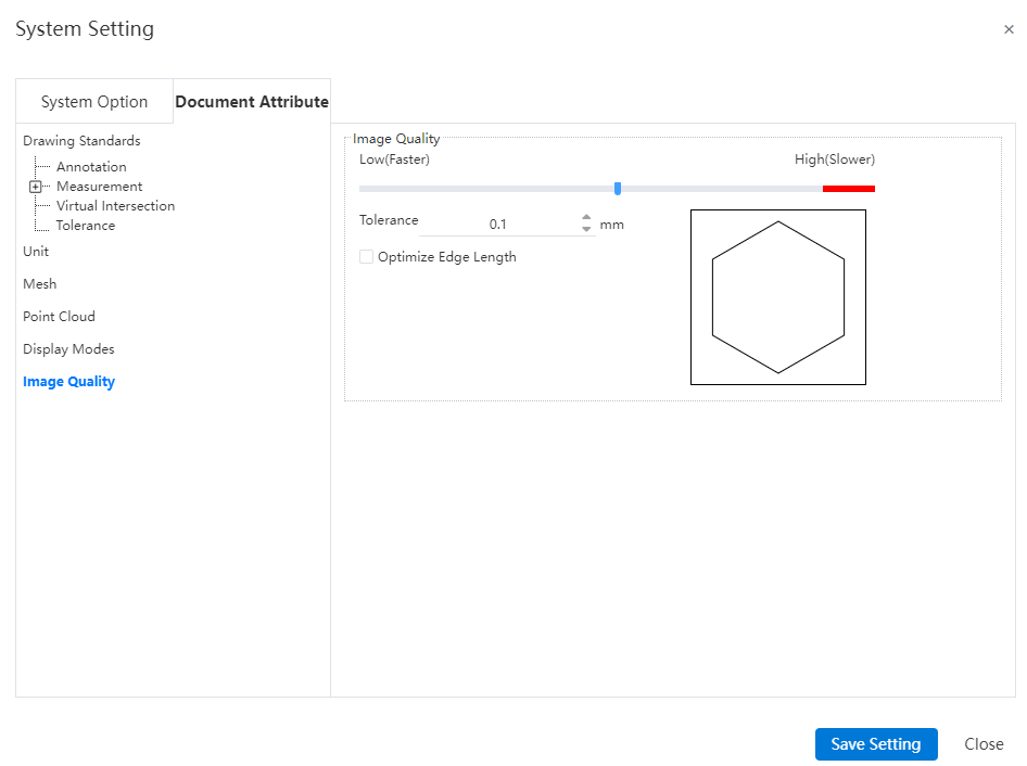
Note: The settings for this interface are saved only with the document and are not saved in the drawing standards.
Control Description:
- Error: Controls the actual maximum chord error. The smaller the value, the higher the display precision.
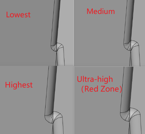
Optimize Edge Length (Higher Quality, Slower): When the error precision setting is at its minimum, selecting this option allows further improvement in image quality.
Apply to All Referenced Part Documents: Selecting this option applies the current assembly document's image quality settings to all referenced part documents, updating the part document's image quality settings to match those in the assembly. Only applicable to assembly documents.
# AI
# Intelligent Command Assistant
The new Intelligent Command Assistant feature alerts users to possible next commands they may need, while continuously learning from their usage patterns to further enhance the user experience.
How to use:
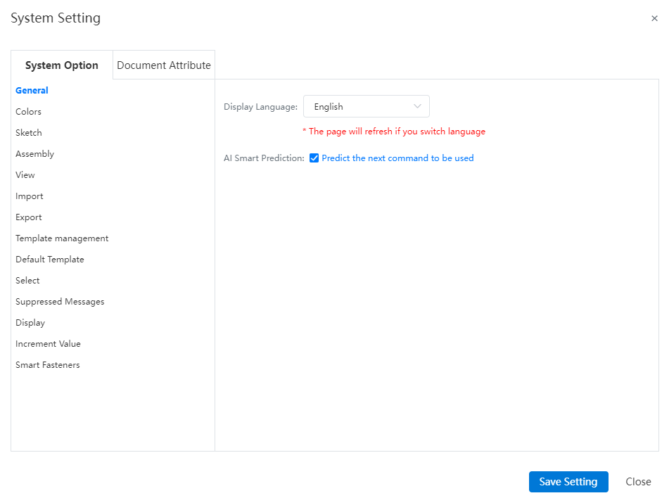
1) Enable AI intelligent prediction.
2) Select the model or sketch elements you want to operate on in the model; the system will automatically predict the next command to use and generate a command list and command menu bar.
3) Click on the desired command from the command list/menu bar, which will activate the command and auto-fill the selected elements.
Note:
- Support configuring whether to enable intelligent predictions and the content of intelligent predictions in "System Settings - General".