# Welcome to CrownCAD 2025 R2
CrownCAD 2025 R2, widely absorb the most authentic feedback from users, to maximize the realization of customer needs. In terms of usability, it is committed to improving customer experience; In terms of functionality, continuously adding commands that customers urgently need can help you quickly complete product design and development work.
Major enhancements:
| Sketch | Enhanced 3D point feature to draw points directly on a surface and automatically add constraints. |
| Enhanced array feature with array generation element support for editing. | |
| Optimized constraint leads, support for referencing external points as a reference, and display horizontal/vertical constraint leads between the mouse cursor and external points. | |
| Optimize spline curve interaction, support right click or double left click to end the drawing. | |
| Parts and Features | Enhanced segmentation features with support for selection lines as segmentation tools. |
| Enhanced datum level function, point normal type added "curve length percentage" option. | |
| The Datum feature adds the tangent type of the curve. | |
| Enhanced transform function, transform mode to add point to point. | |
| New Save as mirror part function, you can directly create a new part that mirrors the current part. | |
| Scan boss, scan excision function is enhanced, support to pick up solid surface/surface as scan outline. | |
| New control point surface function, freely modify the shape of the surface by adjusting the control point of the surface. | |
| Assembly | Symmetrical fit optimization, supporting the selection of two elements of the same part with other parts of the face scale. |
| The new intelligent fastener function can automatically insert standard parts matching the model in the assembly. | |
| New virtual parts feature that allows parts to be stored within the assembly without generating separate documentation. | |
| Added subcomponent ordering, which allows you to drag and drop the order of component instances in the list and control the order in the material specification. | |
| Animation function is enhanced, supporting the explosion view, animation as a video to save to the local. | |
| New Large Assembly mode, in which parts can be kept lightweight and restored. | |
| New search filter function, support in the assembly panel search filter parts, features, etc. | |
| Drawings | Section View command Enhancement, new "Align" mode, which can be used to create a rotated section view. |
| Section view details optimization, section view label default position adjusted to the top of the view, while supporting drag and drop the section line, the section symbol to modify the position. | |
| New total tolerance table command, support to create total tolerance table. | |
| Part serial number dialog box layout optimization, while increasing the number of Settings of the location, logo and other details. | |
| New "size center" function, which can keep the size in the middle position of the size line. | |
| Added the function to hide the size line and size line. | |
| Added the ability to hide model edges in view. | |
| Added annotations that belong to views. After locking a view, you can create annotations that belong to views. | |
| Evaluation tool | New "Check Entity" command, which can be used to automatically find invalid faces, invalid edges, short edges, and other elements in the model. |
| New "Geometry Analysis" command, which can identify geometric entities in a part that may cause problems. | |
| The Document Compare command has been enhanced with the new Compare Features feature, which allows you to compare different features in a document. | |
| Sheet Metal | Sheet metal module overall enhancement, command support undo redo. |
| Data Conversion | Added "Export Geometry" function, you can customize which entities, surfaces and other geometry in the exported file. |
| Added Export format, added export FBX format. | |
| Import optimization, support to import SOLIDWORKS, CATIA format model datum. | |
| MBD | New center symbol line command, support for creating a center symbol line to identify the center point of the element. |
| New center line command, support to create the axis of the rotating surface. | |
| Settings | Enhanced customization - Keyboard function, shortcut keys support setting more types, such as multiple letter, number combinations. |
| Tools | New Add window function, multiple documents can be displayed in the same window. |
| Render | Added isolated parts in the assembly document to allow isolated view of parts in the assembly. |
| Added support for picking up points, lines and surfaces generated by section view for measurement. | |
| Added render mode without material shading, which can be changed in scenes that need to have materials but do not need to display the appearance of materials. |
# Sketches
# 3D dot
When you create a drawing point in a 3D sketch, it can be drawn directly on the surface, and constraints are automatically added between the points and the surface.
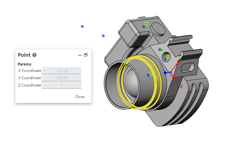
How to use:
1) Go to 3D Sketch.
2) Click the "Point" command.
3) Point the mouse to the surface of the point you want to draw. The highlighted surface indicates that the surface has been captured.
4) Click the left button to create the draw point.
# Array elements are editable
In the sketch, the elements generated by the array function support editing, such as adding rounded corners, etc.

# Optimize the constraint leads
References to external points as a reference are supported in the sketch, and horizontal/vertical constraint lead lines are displayed between the mouse cursor and the external point.
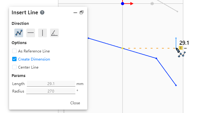
How to use:
1) Go to 2D sketch.
2) Launch a draw command such as "Straight Line".
3) Point your mouse at the external point you want to reference for a short pause.
4) Move the mouse vertically or horizontally to display a dotted guide line for restraint.
5) Click the left mouse button to specify a point in the direction perpendicular or horizontal to the external point.
6) Continue to specify other points to finish drawing.
# Optimize spline curve interaction
Support for right-clicking or double-left-clicking to end drawing.
How to use:
1) Enter 2D or 3D sketch.
2) Launch the "Spline Curve" command.
3) Specify, in turn, the points through which the spline curve will pass.
4) Double-click the left button to finish drawing.
5) Or right click in the blank space of the viewport to finish drawing.
Instructions:
Double left click and the spline curve will pass through the last double-clicked point.
Right-click and the spline curve will not pass through the last right-clicked point.
# Parts and Features
# Division
Support selection lines as a splitting tool.
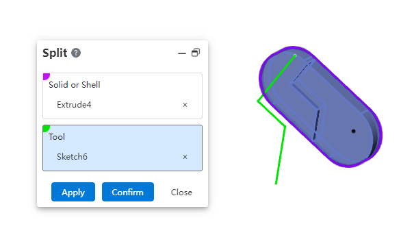
Instructions:
Select the 2D sketch and split the solid, surface along the normal direction of the sketch plane.
Selecting a 3D sketch or spatial curve that exactly coincides with the surface can split the surface, but not the entity.
# Datum Surface
Point Normal type adds the "percent of Curve Length" option to control where the datum is generated by specifying a percentage on the curve.
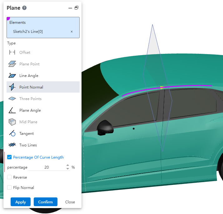
How to use:
1) Open the "Datum" command.
2) Select the "Point Normal" type.
3) Check the "Curve Length Percent" option.
4) Pick up the curve for which you want to create the datum.
5) Modify the percentage value and the datum preview appears where the corresponding percentage is.
6) Click OK to finish the creation.
Note: Check "Reverse" to calculate percentages from the other end of the curve.
# Base Line
New tangent types for curves to increase flexibility in how the base line is generated.
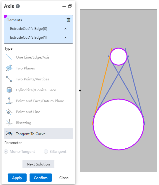
How to use:
1) Open the "Baseline" command.
2) Select the "Tangent of a curve" type.
3) Pick up two coplanar curves, or pick up a curve and a point.
4) When displaying multiple base line previews, it means that there are multiple solutions, switch the desired result via the "Next solution" button.
5) Click "OK" to finish the creation.
Note: When picking a curve and a point, you can set Single cut mode and Double cut mode.

# Transform
Transform method to add point to point, can quickly and accurately position the pieced together two entities.
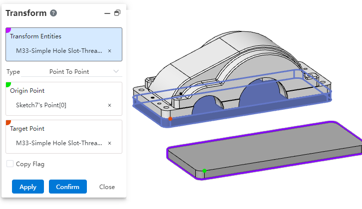
Usage:
1) Open the Transform command.
2) Select the "point to point" method.
3) Pick up the transform object.
4) Specify starting point, destination point.
5) Click OK to finish the creation.
# Save as an image part
New "Save as mirrored part" function. When designing a part with left and right symmetry, you can directly use this function to create an image part without having to re-model the entire part, improving design efficiency.
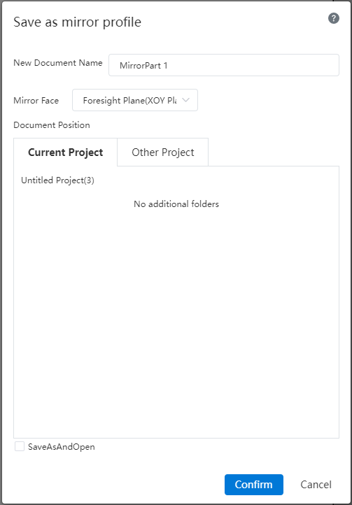
How to use:
1) Click the "Save as mirrored Part" command in the Save button drop down box.
2) Set the new document name, mirror plane, and document location in the dialog box.
3) Check "Save and Open" as needed to open the document automatically after it is generated.
4) Click "OK" to create the mirror part in the document location you set.
# Scanning boss/scanning excision
Scanning bosses, scanning excision supports picking up solid/curved surfaces as scan contours.
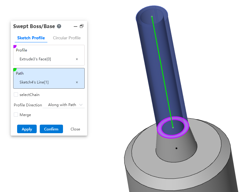
How to use:
1) Open the "Scan boss/substrate" or "scan Excision" command.
2) Select the "Sketch Outline" mode.
3) Pick up solid/curved surfaces as scan Outlines.
4) Pick up the scan path.
5) Click OK to finish the creation.
Note: You must select a plane.
# Control point surface
New control point surface function, by adjusting the control point of the surface to freely modify the shape of the surface.
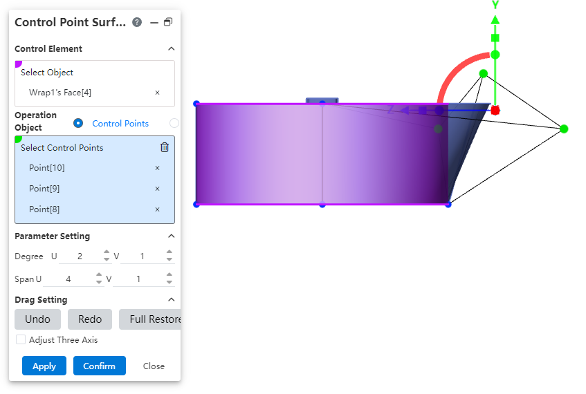
How to use:
1) Open the "Control Point Surface" command.
2) Select the physical surface of the shape you want to modify as the "control element".
3) Modify the number of times, span number, to adjust the number of control points on the face.
4) Select the control points or control lines to adjust as needed.
5) Drag the triple axis to change the position of the control point/line to distort the surface.
6) Continue to pick up other elements and drag the triple axis to adjust the surface.
7) Click OK to finish the creation.
Dialog box control description:
Control Elements - Select Object: Select the surface you want to adjust.
Control Object: Select the control point or control line on the surface you want to adjust.
Select Control point/line: Select the control point/line you want to adjust.
Parameter Settings: Used to display and modify the number of times and spans of the face in the UV direction.
Undo: Click to undo the drag and drop of the triple axis in the previous step.
Redo: Click Cancel to undo the drag and drop action on the previous triple axis.
Full Restore: Click to resume all drag-and-drop operations on the triple axis in this command
Adjust Triple Axis: Check this to drag and drop the triple axis to adjust the position of the triple axis without affecting the control point/line.
Triple axis instructions:
Drag the triangle symbol on the axis to translate the control point in the direction of the corresponding axis.
Drag the square symbol on the axis to scale the control point in the direction of the corresponding axis.
Drag the spherical symbol on the axis to rotate the control point around the corresponding axis.
Click the square symbol on the axis and drag the square at the origin of the triple axis while scaling the control point in three directions.
# Assemble
# Symmetrical fit
Symmetrical fit supports the choice of two elements of the same part with the other parts facing each other.
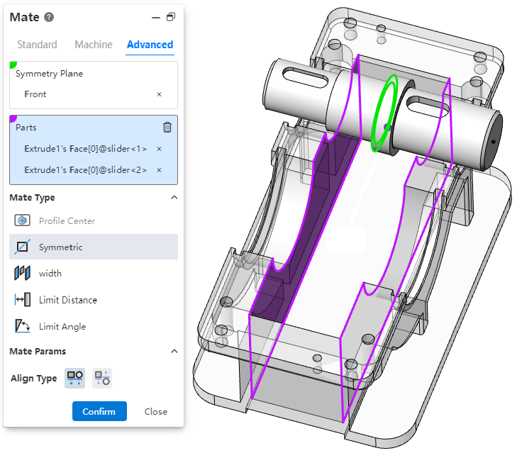
Description: The two faces of the part must be parallel.
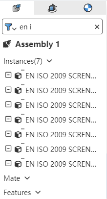
# Smart fasteners
New smart fastener command, which can automatically insert standard parts matching the model in the assembly.
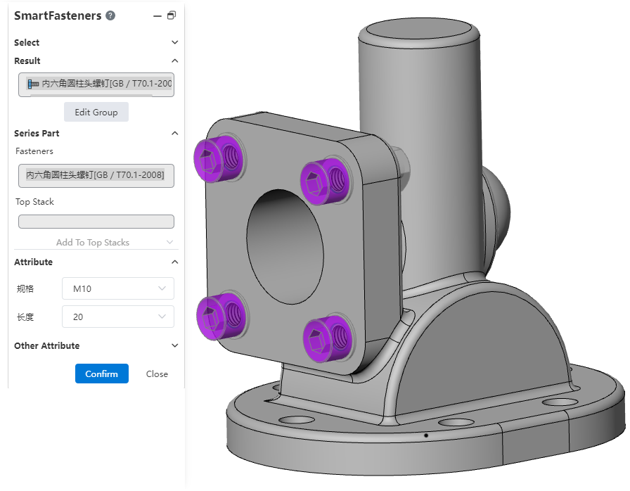
Usage:
1) Open the "Smart Fastener" command.
2) Select the part or punch face to which you want to add the fastener.
3) Click the "Add" button to display a preview of the fastener.
4) Right-click the fastener to change the fastener type.
5) Click Edit Group, you can drag and drop to modify the group.
6) Set the properties of the fasteners corresponding to each group as needed, and add laminated parts (gaskets, etc.).
7) Click "OK" to finish adding.
Instructions:
You can delete unnecessary fasteners or groups by right-clicking them.
For holes with specifications generated by the hole command, the fasteners of the corresponding specifications are automatically selected by default.
The default fasteners corresponding to stretch cut and simple straight holes can be set in "System Settings - Smart fasteners".
Holes in the same group will use fasteners of the same specification, and holes in the same series will generate a smart fastener feature.
# Virtual Parts
New "Virtual Parts" feature. In the preliminary design stage, the assembly structure and parts need to be changed frequently. Virtual parts are stored in the assembly without generating independent documents, which can be quickly added, deleted, changed and checked to avoid producing a large number of invalid part documents and documents with the same name. After the design is completed, the virtual parts can be converted into ordinary parts for the subsequent process.
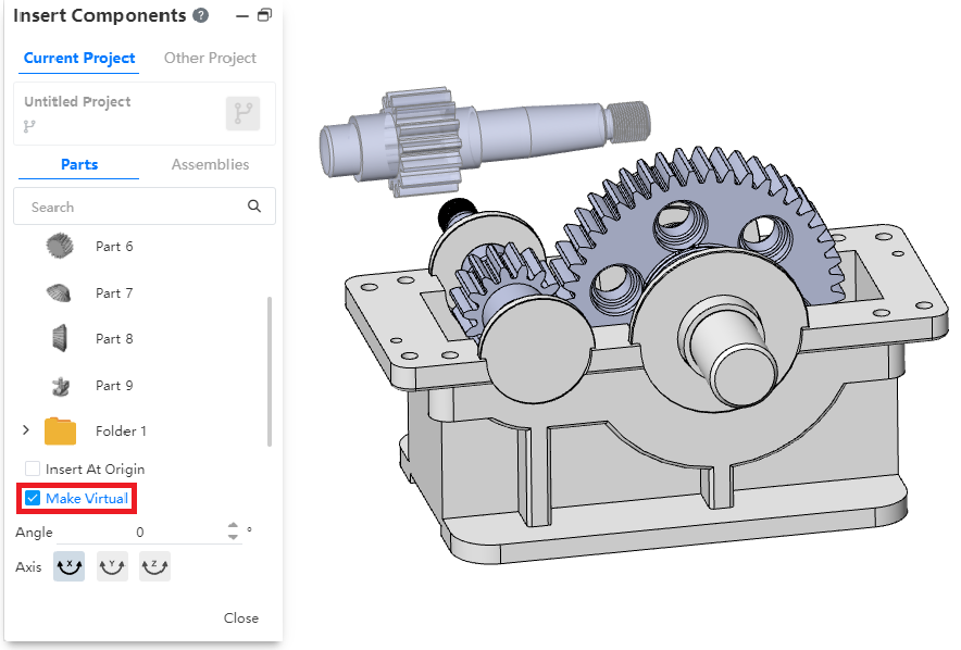
Method 1 of Use - Insert new virtual parts:
1) Open the "Insert Part or Assembly" command.
2) Check "Make Virtual".
3) Select parts for insertion, and after insertion is virtual parts.
4) Edit the virtual parts.
5) Right click virtual part - Save document.
6) Set the document name and path and click OK.
7) Save virtual parts as normal parts document.
Usage Method 2- Convert existing parts to virtual Parts:
1) Right-click an existing part in the assembly and click "Make Virtual" to convert it into a virtual part.
2) Edit virtual parts.
3) Right click virtual part - Save document.
4) Set the document name and path and click OK.
5) Save virtual parts as normal parts document.
# Sequence of sub-parts
Supports drag and drop the order of component instances in the list, while controlling the order in the material list.
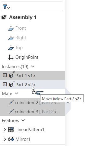
How to use:
1) Open the assembly.
2) Drag and drop the part instance while holding down the left mouse button in the feature panel.
3) Release the left button where you want to place it to complete the drag and drop.
Note: Reordering can only be done in the same level of the same assembly.
# Animations
Animation explosion view, animation support save as video to local.
Animation - Save method:
1) Double-click on the animation list to activate the animation you want to save.
2) Click the "Export" button in the toolbar.
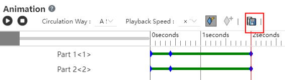
3) Set your video parameters.
4) Click OK to finish saving.
Animation Explosion View - Save method:
1) Right click on the Explosion View in the View panel and select "Animation Activated".
2) Pause the play.
3) Click the Export button.

4) Set the video parameters.
5) Click OK to finish saving.
Dialog box description:
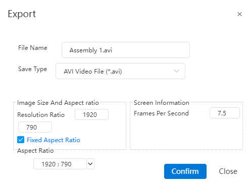
File name: Set the name of the exported video file.
Save type: Set the type of video file to be exported.
Resolution: Set the video resolution.
Fixed Aspect Ratio: Check this to keep the selected "Aspect ratio" when modifying the resolution.
Aspect Ratio: Set the aspect ratio of the video.
Frames per second: Sets the number of frames of the video.
# Large assembly mode
1 The lightweight and reduced state of parts can be maintained in large assembly mode. When the large assembly is opened, refresh the web page or switch the document, the system will keep the restore state of the parts and avoid repeatedly setting the state of the parts.
2 In the large assembly mode, you can directly right-click to edit features, fits, etc., and the system will automatically restore relevant parts after prompting for editing.
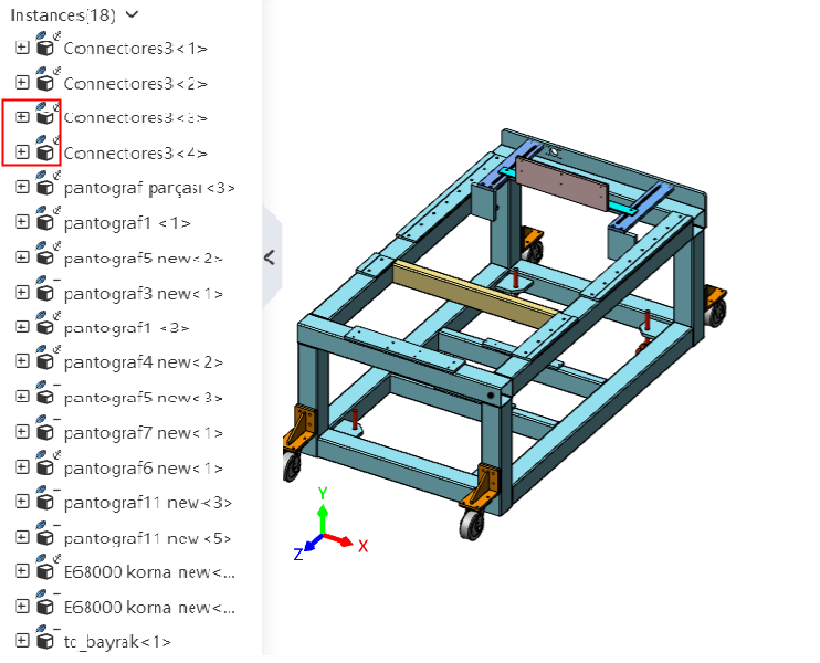
# Search Filter
Support for search filtering parts, features, etc. in the assembly panel.
How to use:
1) Click the button in front of the search box.
2) Make your search Settings in the menu that pops up.
3) Type characters into the search box.
4) Based on the characters entered, the automatic filter displays eligible parts, features, etc.
# Drawing
# A rotating section view
The Cesarean View command adds the "Align" method, which can be used to create a rotated Cesarean view.
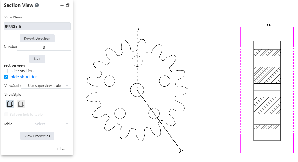
How to use:
1) Click the "Section View" command.
2) Select the "Align" mode in the dialog box.
3) Click 3 points in the view you want to cut to generate a cut line. The first of these points is the turning point of the cut line.
4) Add offsets to the cut line as needed.
5) Click "√".
6) Place the section view to finish creating.
Hide the Split shoulder: After adding offsets on the split line, use this option to control whether the line at the offset of the split line is displayed on the split view.

# Cutaway view
The cutaway view is optimized for multiple details.
- Support direct drag on the parent view of the section line, modify the position of the section line.

- Supports drag and drop the labels at both ends of the parent view profile line to modify the position.

- The default position of the sectioned view label is adjusted to the top of the view.

# Total tolerance table
Added the Total Tolerance table command to support the creation of total tolerance tables.
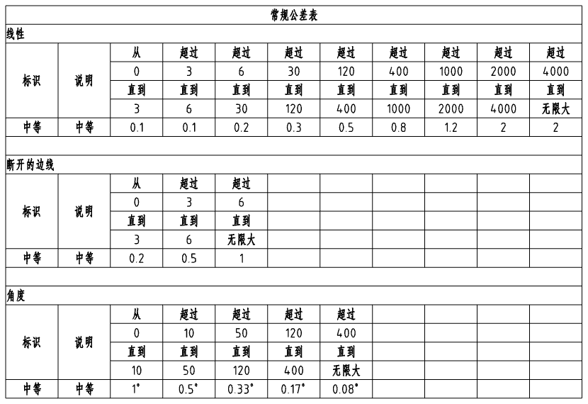
How to use:
1) Click the "Total Tolerance Table" command.
2) Select the view and other parameters you want to associate.
3) Click in the viewport to bring up the tolerance table preview.
4) Click Place tolerance table in the viewport to complete the creation.
Instructions:
Open the parts document and modify the tolerance level of the parts in "System Settings - Document properties - drawing standard - tolerance".
The custom tolerance level can be modified in "System Settings - Template Management - Total Tolerance Table".
# Part Serial number
- Optimize the layout of part serial number dialog box to improve the interface ease of use.
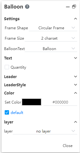
- Support to set the quantity of the location, logo and other details.
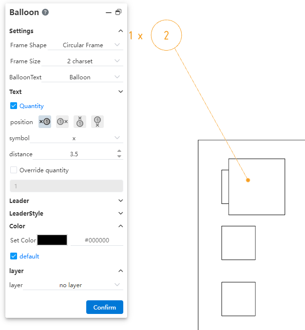
Place: Set which side of the serial number symbol the quantity is placed on.
Mark: Set the mark between the quantity and the symbol.
Distance: Set the distance between the quantity and the symbol.
Custom quantity: The numerical value used to define the quantity.
# Size centered
New "Size Center" feature to keep the size in the middle of the size line.

How to use:
1) Click to select the size you want to center.
2) Click the Size Center button in the dialog box.
3) Drag the size within the size boundary line to automatically position it in the middle.
Description: The center function does not take effect when the size is outside the size boundary line.
# Hide size boundaries, size lines
Support hiding size lines, size lines.

How to use:
1) Right-click to hide the size line, size line.
2) Click "Hide Size Lines, Hide size Lines" in the right-click menu.
3) Right-click the size and you can restore the display.
# Hide/show the edges
Support for hiding model edges in view.
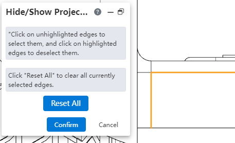
To use Method 1:
1) Right click on an empty space inside the view.
2) Click the "Hide/Show Margins" command.
3) Click the edges inside the view and set the edges that you want to hide to highlighted checked.
4) Click OK to hide the selected edge line.
To use Method 2:
1) Right click on the edge that the view wants to hide.
2) Click the "Hide/Show Edges" command.
3) The right edge is hidden.
4) Use Method 1 to unhide.
# Annotations that belong to the view
After you lock a view, you can create labels that belong to the view. Labels that belong to the view move with the view.
How to use:
1) Double click on the view and set it to lock focus.
2) Create a label such as surface roughness in the blank space, which belongs to the locked focus view.
3) Drag and drop the view so that the annotations within the view move with the view.
# Evaluation Tools
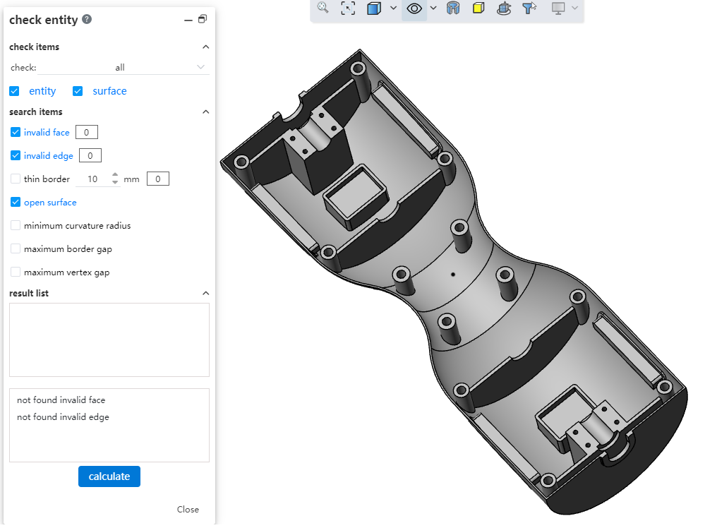
# Checking entities
New "Check entity" command, which can be used to automatically find invalid faces, invalid edges, short edges, and other elements in the model.
How to use:
1) Click the "Check Entity" command.
2) Set the scope and type of the check item.
3) Check the items you want to look for.
4) Click Calculate and wait for the calculation to complete.
5) Click the found item in the list of results, the viewport is highlighted, and the details of the item are displayed in the box at the bottom of the dialog box.
6) Click Close to end the inspection.
Dialog box control description:
Check items: Select the content and type to check, you can select all or manually specify the options.
Search items: Check the elements you want to look for.
The box following "Invalid face, invalid edge, Short edge line" will display the number of corresponding elements once the calculation is complete.
"Short Edges" allows you to set the length value of the edges.
Result list: After the calculation is complete, the found element is displayed. Click the element to display the specific information.
Isolated: Available only in assembly, select an element in the result list and click Isolate to display the instance where the selected element is located.
Close and Isolate: Available only in Assembly, select an element in the result list, click Close dialog and isolate the instance where the selected element is located.
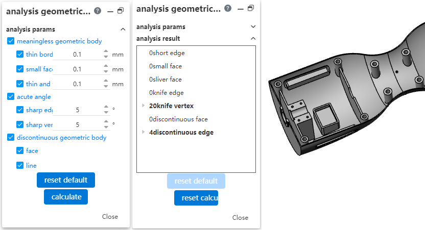
# Geometry analysis
New "Geometry Analysis" command to identify geometrical entities in parts that may cause problems.
How to use:
1) Click the Geometry Analysis command.
2) Set what you want to analyze and the parameters.
3) Click Calculate and wait for the calculation to complete.
4) Click the item you found in the analysis results and highlight it in your viewport.
5) Click Close to end the analysis.
Dialog box control description:
Analysis parameters: Select what you want to check and set its parameters.
Analysis results: Display the results of the analysis.
Restore default: Click to restore analysis parameter Settings.
Compute: Click Start to compute.
Description of the analysis parameters:
Meaningless geometry:
Short edges: Edges below the specified length.
Small side: A side where all sides are below the specified length and the face area is less than the square of the specified length.
Thin thin face: A face with a high ratio of height to width.
Sharp corners:
Sharp edge line: A edge line where the Angle between two adjacent faces is less than the set value.
Sharp vertices: The Angle between two adjacent edges is less than the vertices of the set value.
Interrupted geometry:
Face: A face in which a discontinuous region of position or curvature exists.
Edge line: A line in which an area of position or curvature discontinuity exists.
# Document Comparison
Document Comparison command Added the feature comparison function to compare different features in documents.
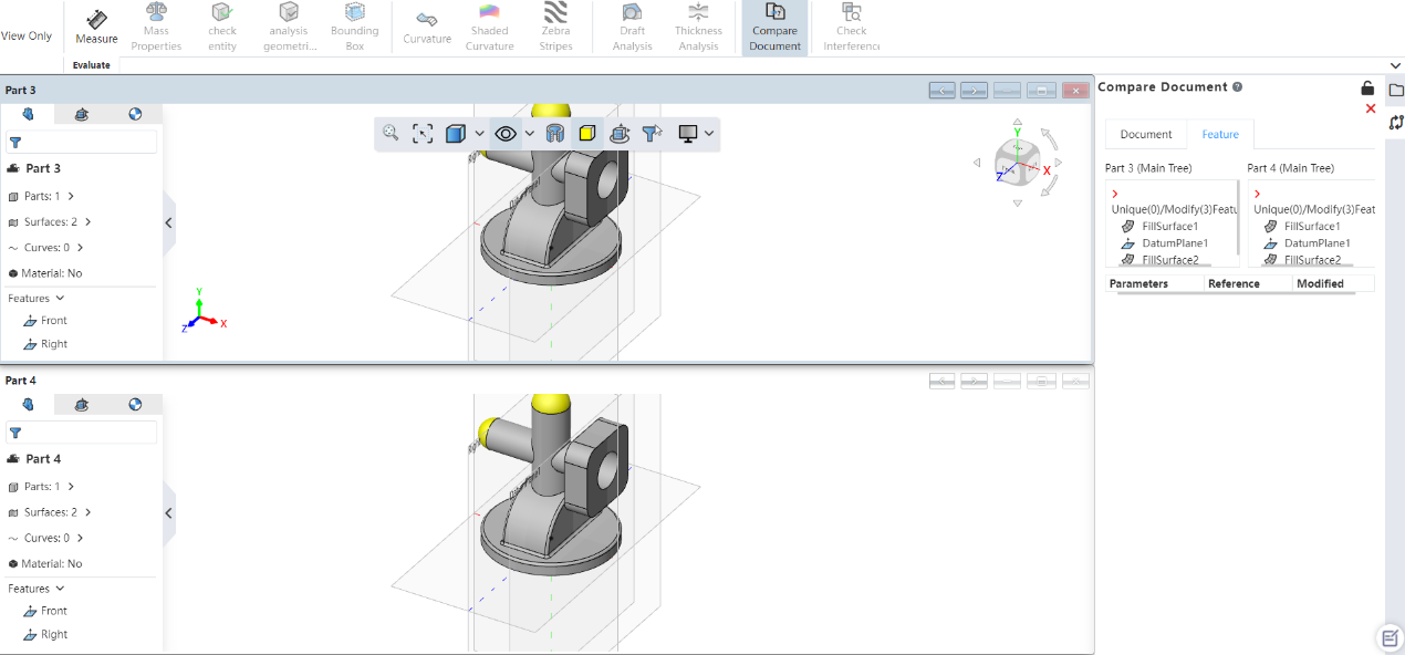
How to use:
1) Click the Document Compare command.
2) Set the reference document and the document you want to compare.
3) Check "Features" in the comparison item.
4) Click Calculate and wait for the calculation to complete.
5) Switch to the "Features" Tab to see the results of the feature comparison.
6) Click Exit Comparison to end the command.
# Data conversion
# Exporting geometry
New "Export Geometry" function, you can customize the solid, surface and other geometry in the export file.
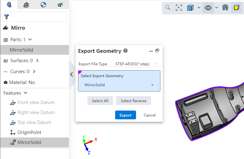
Use Method 1:
1) Right click on the geometry you want to export.
2) Click Export Geometry.
3) Select the geometry you want to export and the export format.
4) Click Export to finish exporting.
Use Method 2:
1) Click the Export command from the Import/Export drop-down menu.
2) Click the "Select Geometry to Export" button.
3) Select the geometry you want to export and the export format.
4) Click Export to finish exporting.
Dialog box control description:
Export format: Set the file format to be exported.
Select geometry to export: Used to select geometry to export.
Select All: Click on the geometry in the document to select all.
Reverse: Click to reverse the geometry in the document.
# Export format
Added support for exporting FBX formats.
Support for exporting OBJ\FBX format files with maps.
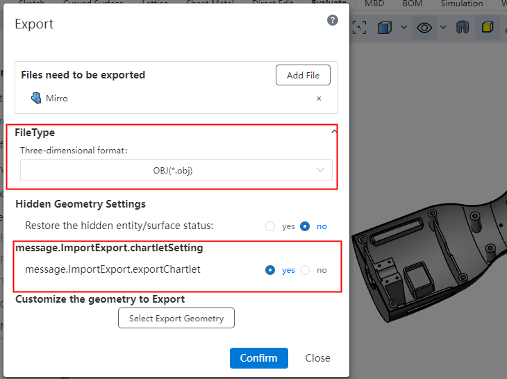
How to use:
1) Open the model with a map that you want to export.
2) Click the Export button in the Import/Export drop-down menu.
3) Set the export format to OBJ or FBX.
4) Set the export map option to "Yes".
5) Click OK.
# Import datum
Support to import SOLIDWORKS, CATIA format model datum.
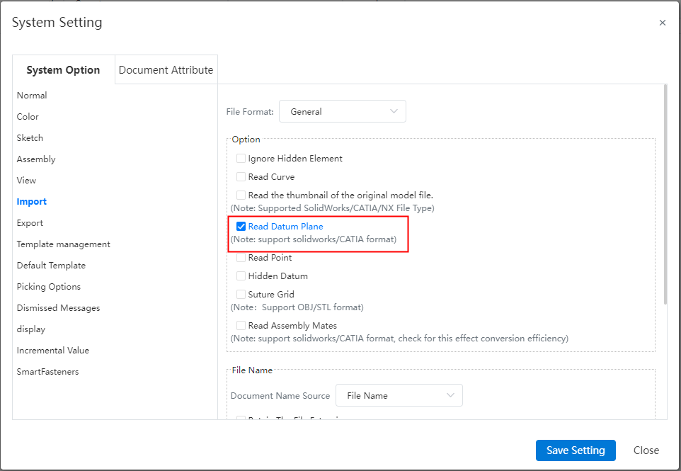
Usage:
Open System Settings and click System Options-Import.
Check Read datum (not checked by default).
# Import/export CrownCAD file
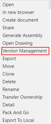
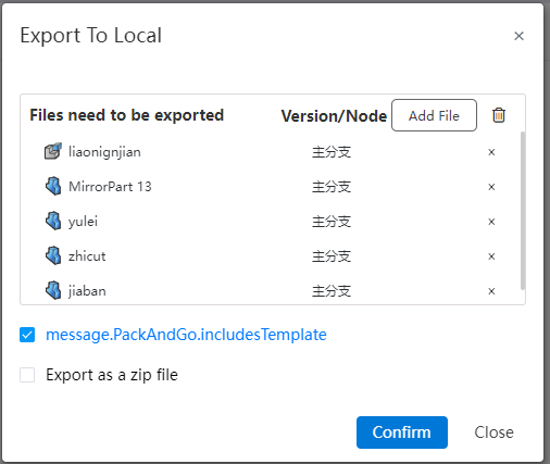
Added the CrownCAD file import and export function. You can click Export to Local and Import CrownCAD File in Import/Export. When exporting, you can decide whether to export the CrownCAD file including engineering drawings, standard parts, and templates.
Directions to use:
Export to local:
Select [Export to Local] from the Import/Export drop-down box.
Set the check box to control the special content to be included when exporting, including drawings/standard parts and templates.
Select Nested View/Flat View to set whether to indent the files in the file list according to their affiliations.
File list, check what you want to pack.
Number of documents: Displays the number and total number of selected documents for each category to be packaged.
Document structure: Select the structure of the exported document.
Compressed package name: Enter the compressed package name, which defaults to the project name.
Click Export, select the template to be exported, support the user manual search or the system automatically search according to the selected document.
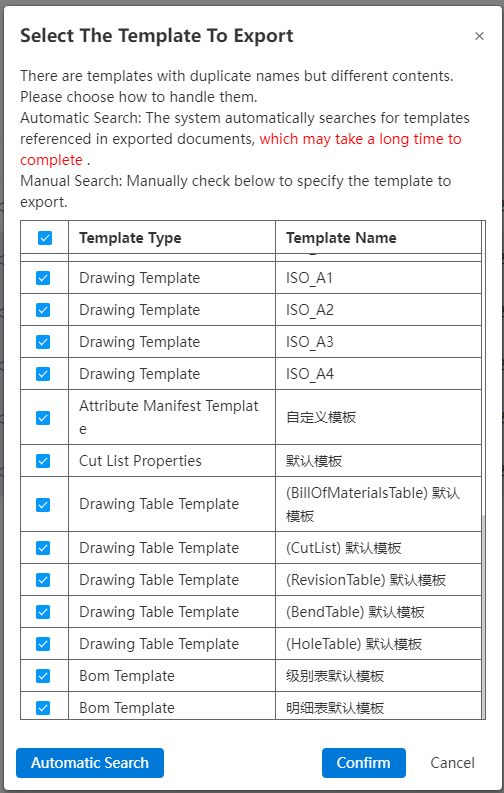
- Click OK.
Import the CrownCAD file:
Import, click the Import/Export drop down box and select Import CrownCAD file.
Package the model file along with the referenced template file.
Confirm the import, the system automatically recognizes and uses the template file.
Instructions:
When exporting the template file, the template file and model file are packaged as a zip compression package.
You can upload the template file as an unpacked file or as a ZIP package, but you cannot upload the template file together.
# MBD
# Center symbol line
New center symbol line command, support for creating a center symbol line to identify the center point of the element.
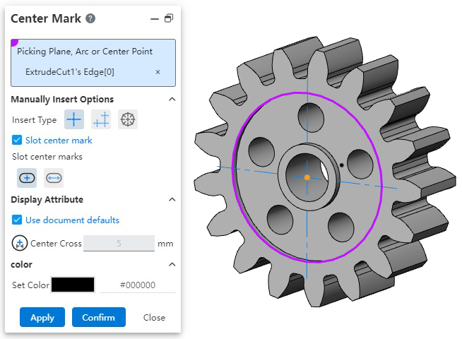
How to use:
1) Right-click in the view panel to activate the view in which you want to place the annotation.
2) Click the Center Symbol Line command.
3) Pick up the round element to which you want to add the center symbol line.
4) Set the insert type, style, etc.
5) Click OK to finish inserting.
# Center Line
Added center line command to support the creation of axes of rotating surfaces.
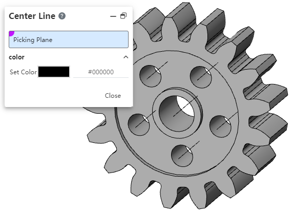
How to use:
1) Right-click in the view panel to activate the view you want to place the annotation on.
2) Click the "Centerline" command.
3) Set the color.
4) Pick up the rotating surface where you want to add the center symbol line and insert it automatically.
5) Click Close.
# Settings
# Custom - Keyboard
Shortcut keys support setting more types, such as multiple letter and number combinations.
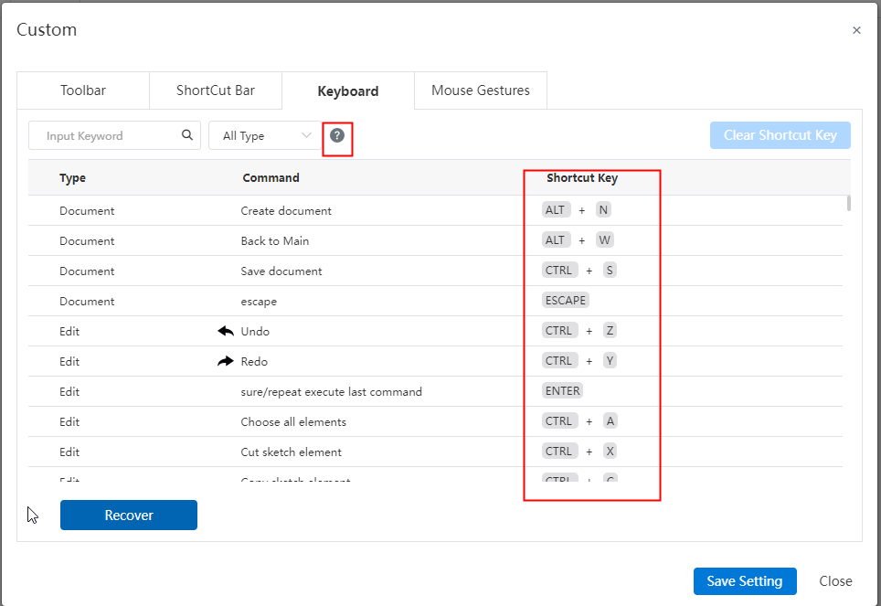
Note: Click the question mark button to view the operation prompt.
# Tools
# Multiple Windows
New increase window function, when open multiple documents, multiple documents can be tiled under a window, and can be operated normally. Convenient for you to view the contrast effect between documents.

How to use:
After selecting any document to open, click [Window] button in the navigation bar.
Click the drop down button and select the tile effect [horizontal tile] or [Portrait tile].
Instructions:
No more than 32 documents can be opened.
After refreshing the web page, keep only the last activated documents.
# Render
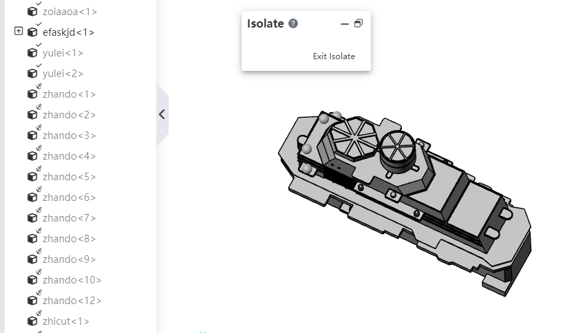
# Isolate
Added the ability to isolate parts in assembly documents. At the same time, you can set the display mode for unselected parts to facilitate viewing or editing the parts in the assembly.
Usage:
Open the assembly document.
Right click on the instance list or viewport to select parts/folders and click Select Isolate.
The Isolated dialog box pops up, and the other instances are hidden except for selected parts/folders.
Click Exit isolation to restore the pre-isolation state. The creation of other functions is affected.
Description:
- Under Topdown (edit sub-assembly) instance isolation is not supported.
# Cutting measurement
Create section views in parts and assemblies, and add measurement commands to support picking up points, edges, and cross section elements generated by cutting.
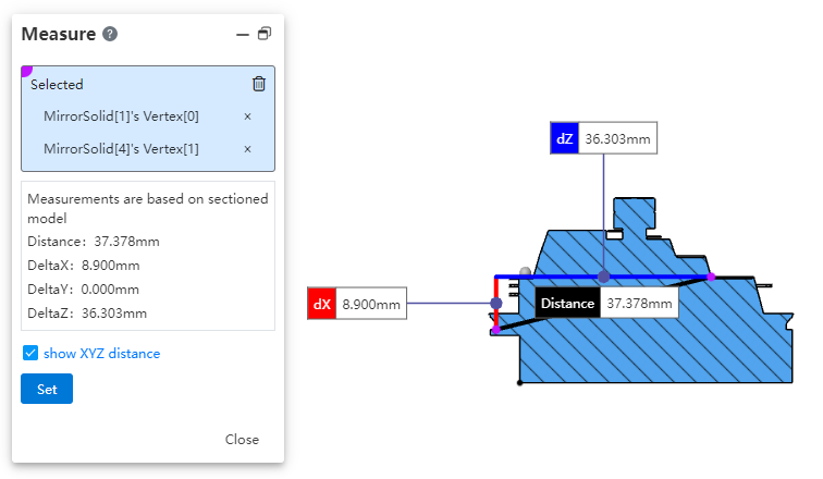
How to use:
1) Create section views in parts and assemblies.
2) Open the Evaluation [Measure] command and pick up the point, line, and surface elements generated by the cutaway for measurement.
# Material rendering
Added "Without Material coloring" to the rendering mode of the view toolbar. Make it easy for you to change the render mode in scenes where some parts need to have a material but do not need to show the appearance of the material.

Instructions:
- When switching to [without material coloring], only the appearance of the material is not displayed, and the rest of the display effect is the same as the coloring.
# Cables
# Electrical parts library
Add system preset electrical parts to the electrical parts library, which can be directly invoked.
Instructions: System preset electrical parts can not be edited, deleted, can only call.