# Sheet Metal
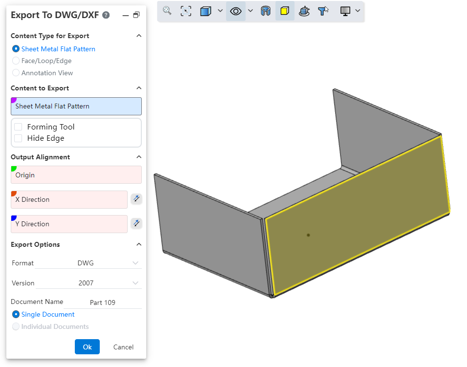
# Export To DWG/DXF
Added export to DWG/DXF functionality ,To easily one-click export engineering drawings with the outlines of sheet metal flat layout models.
Usage Method:
1) In the Import /Export dropdown menu,click on “Export to DWG/DXF ”.
2) Select the content type, content, alignment, file format, etc. to output.
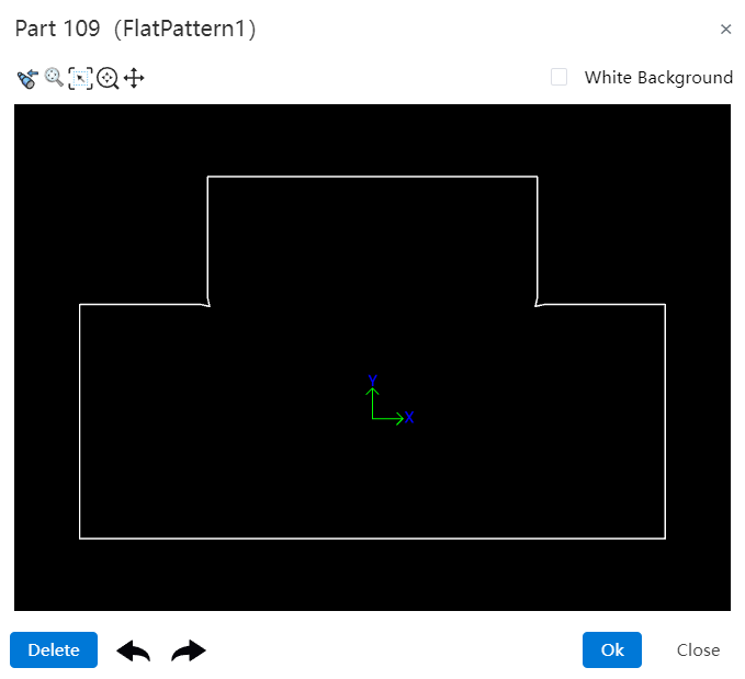
3) Click OK, and a preview window will appear.
4) In the preview window, you can select the unwanted lines and click 'Delete' to remove them.
5) When exporting multiple contents, you can use the left and right buttons to switch between drawings.
6) In the preview window, click OK to complete the export.
Dialog Box Controls Guide:
Output Content Type: Used to select the type of content you want to output.
Sheet Metal Flattened Style: Outputs views of sheet metal in flattened style. This option is only available for sheet-metal parts. When there are multiple sheet metals, each can be output as a separate flattened view.
Faces/Rings/Edges: Select parallel faces or edges and project them onto the same plane to output as an engineering drawing.
Annotation View: Select one or more view directions to generate views of the selected directions.
Objects to Output: Depending on the selected output content type, choose the corresponding objects to output.
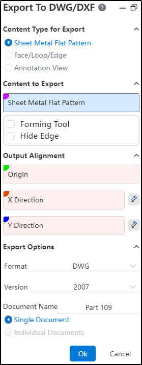
Output Alignment: Set the point in the model that will align with the origin of the engineering drawing and the XY direction. This is an optional setting.
Output Options: Control the file format, version, file name, and how multiple drawings are output。
Dialog Box Controls Guide:
Buttons: From left to right, the buttons are "Previous Page、Previous View、Adaptive、Focus on Selected Area、Zoom、Pan、Next Page."
Previous Page: Click to switch to the previous page.
Previous View: Click this button to return to the previous view.
Adaptive: Same functionality as in the viewport (keeps the content centered and adjusts scale accordingly).
Focus on Selected Area: Same functionality as in the viewport (zooms into a selected area of the drawing).
Zoom: Click, then hold down the left mouse button and drag up or down. Dragging upward zooms in; dragging downward zooms out.
Pan: Click, then hold down the left mouse button to pan(move) the view horizontally or vertically.
Next Page: Click to switch to the next page.
White Background: When checked, this changes the background color of the preview viewport to white.
Delete: Select a line in the preview viewport and click this button to delete it.
Undo、Redo: Undo or redo the delete operation.
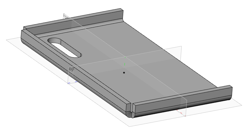
# Normal Cut
When stretching to remove a sheet metal part, adding an Normal Cut option allows for the quick creation of a model that conforms to the characteristics of sheet metal.
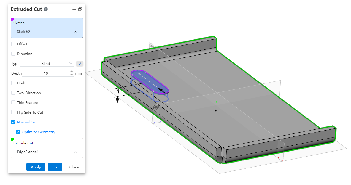
Usage Method:
1) Draw the removal sketch and sheet metal body.
2) Open the Stretch Remove command, select the sketch and sheet metal part.
3) Check the Normal Cut option.
4) Click OK to create a removal feature where the cutting surface is perpendicular to the sheet metal face.
Instructions:
The orthogonal removal option is only available when removing sheet metal parts.
Enabling "Optimize Geometry" will smoothly connect the top and bottom projections of the removed section, facilitating subsequent processing or operations.
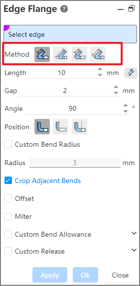
# Edge Flange
The Edge Flange command has been optimized for details. The system will now record the last used "Method". Next time you use the edge flange command, the "Method" will default to the item used in your previous session.
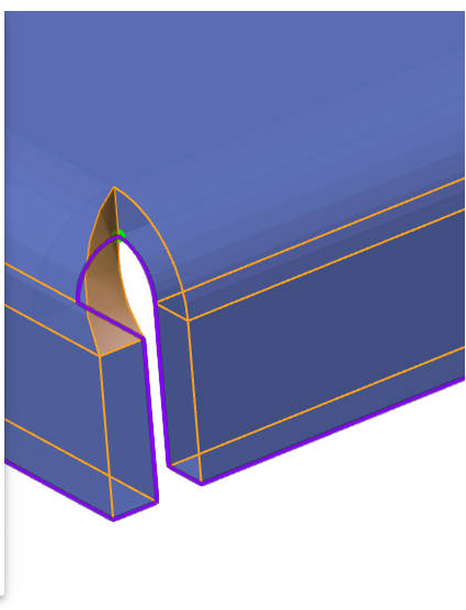
# Corner Relief
A new "Corner Relief" command has been added to handle sheet metal edges and corners.
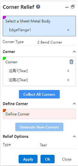
Usage Method:
1) Click the Corner Relief command.
2) Select the sheet metal entity whose corners you want to handle.
3) Click the "Collect All Corners" button, and all processable corners are automatically filled in.
4) Alternatively, pick the bend faces on both sides of the boundary within the "Define Boundaries" selection box, click "Generate New Corner," and manually select the corner that needs handling.
5) Click OK to finish the corner relief operation.
Dialog Box Controls Guide:
Select a Sheet Metal Body: Choose the sheet metal entity where you want to add corner reliefs.
Corner Type: Displays the types of corners that can be processed.
Corners: Shows the selected corners to be handled.
Collect All Corners: Click this button to automatically collect all processable corners on the sheet metal body.
Define Corner: Select the bend faces on both sides of the corner in this section, click "Generate New Corner," and manually add corners to be processed.
Generate New Corner: After selecting the bend faces, click this button to manually add a new corner for processing.