# Drawing
# Break View
- Support dragging the fracture line to change the fracture position.

- When projecting with a fracture view as the parent view, the child view automatically generates the same fracture features as the parent view.

Explanation:
The fracture position of the child view updates according to the fracture position of the parent view and cannot be manually adjusted.
Fracture features are automatically generated only when the projection direction aligns with the fracture line direction.
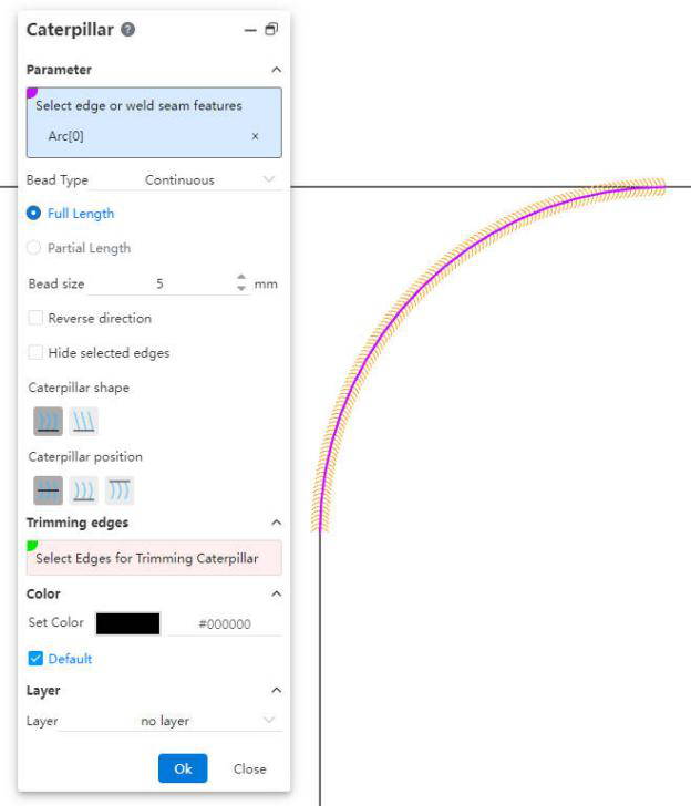
# Caterpillar
Added a " Caterpillar " feature to generate annotations for identifying welds.
Usage Instructions:
1) Click the " Caterpillar " command.
2) Select the edge in the viewport, or expand the component in the view panel to select the weld feature.
3) Set the Caterpillar style, parameters, etc.
4) Click OK to complete the creation.
Dialog Control Descriptions:
Select Edge or Weld Feature: Used to select the edge for generating the " Caterpillar " or the weld feature in a 3D model.
Caterpillar Line Type: Choose to generate either "Continuous" or "Intermittent" Caterpillar. For intermittent types, you can set the length of each segment and the spacing between segments.
Full Length, Partial Length: Control whether the total length of the Caterpillar is equal to the selected edge.
Weld Size: Controls the "width" of the Caterpillar.
Reverse Direction: Checking this option will reverse the direction of the Caterpillar.
Hide Selected Edge: Checking this option hides the edge corresponding to the Caterpillar.
Caterpillar Shape: Used to set the shape of the Caterpillar.
Caterpillar Position: Used to control the position of the Caterpillar relative to the edge.
Trim Edges: Select the edges at both ends of the Caterpillar and use them to trim the ends of the Caterpillar.

- Color, Layer: Set the color and layer of the Caterpillar annotation.
# Smart Dimension
Supports dimensioning with center symbol lines, circular connection lines, and linear connection lines.
# Table
Supports saving tables such as Bills of Materials (BOM) as local files.
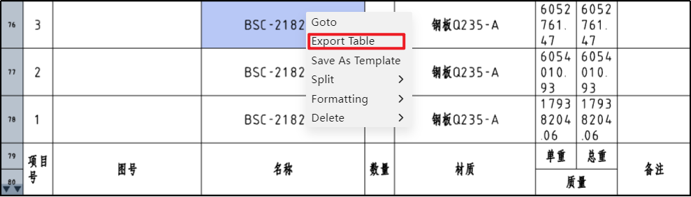
Usage Instructions:
1) Right-click at any position in the table.
2) Click the "Export Table" option.
3) In the pop-up dialog box, set the file format and filename.
4) Click OK to download the file to your local system.

Dialog Control Descriptions:
File Format: Used to select the file format for export. Supported formats include "xlsx, xls, txt, csv."
Filename: Used to set the name of the exported file.
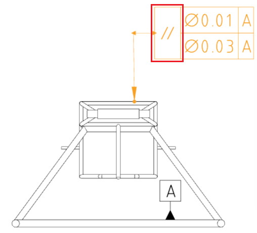
# Geometric Tolerance
# Combined Type Frame
Supports combining frames of the same type of geometric tolerances.
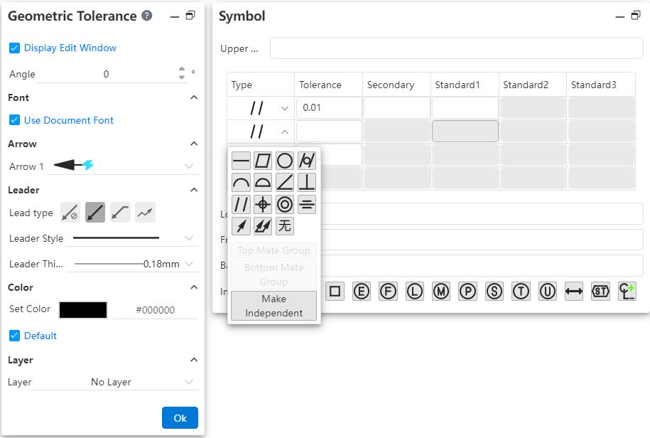
Usage Instructions:
1) Create the geometric tolerance symbols.
2) In the symbol pane, click the drop-down box for the type frame you wish to combine.
3) Select "Combine Above" or "Combine Below" from the pop-up menu to merge this frame with the frames above and below it.
4) Click the drop-down box again and select "Make Independent" to separate this frame from others.
5) Close the dialog box to complete the settings.
# Prefix and Suffix Text
Supports adding text before and after the geometric tolerance symbols.
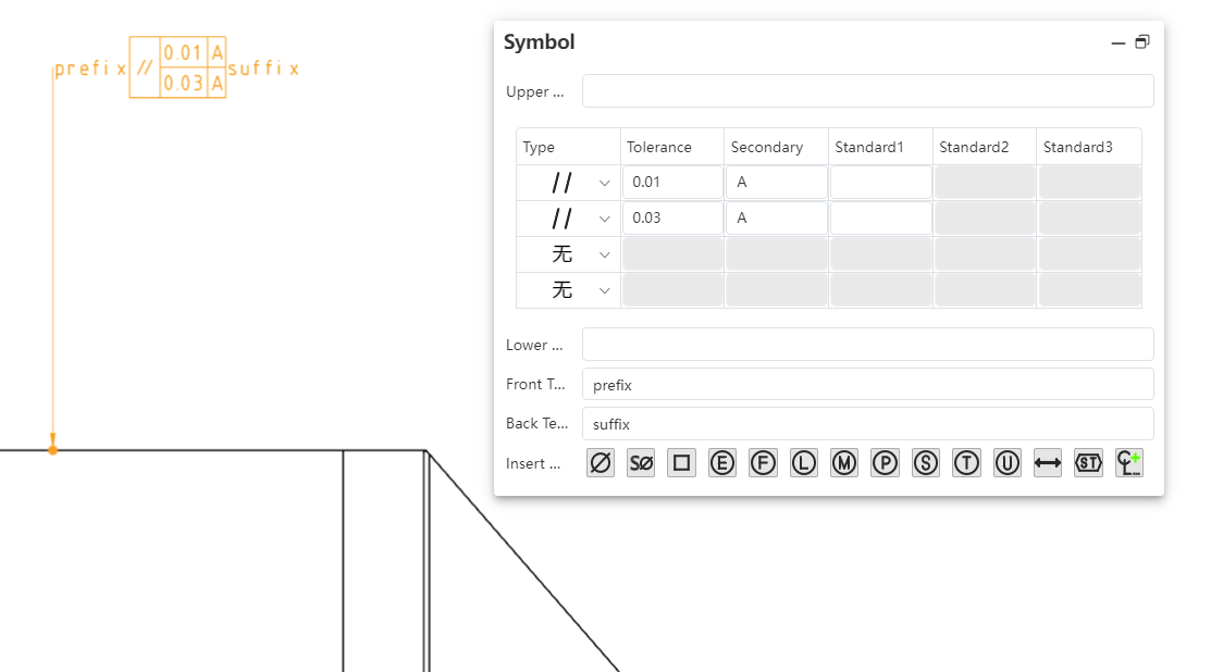
Usage Instructions:
1) Create the geometric tolerance symbols.
2) In the symbol pane, enter text in the "Prefix Text" and "Suffix Text" input fields.
3) The text will be displayed before and after the symbols, respectively.
4) Close the dialog box to complete the settings.
# Symbol Library
A new symbol library feature has been added, allowing the insertion of a wider variety of symbols.
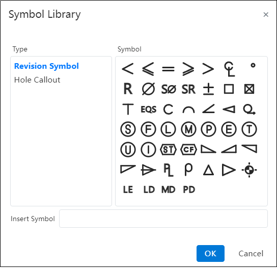
Usage Instructions:
1) Create the geometric tolerance symbols.
2) Click on the input field where you want to insert a symbol, ensuring the cursor is blinking within the field.
3) Click the last button in the "Insert Symbol" toolbar to open the symbol library.
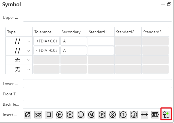
4) In the symbol library, click the desired symbol to be inserted.
5) Click “OK” to insert the selected symbol into the input field.
6) Close the dialog box to complete the settings.
# Frame Alignment
Optimize the frame alignment to ensure that frames remain aligned when entering the same number of digits, Chinese characters, or English letters in different frames. This results in a neater appearance on drawings.

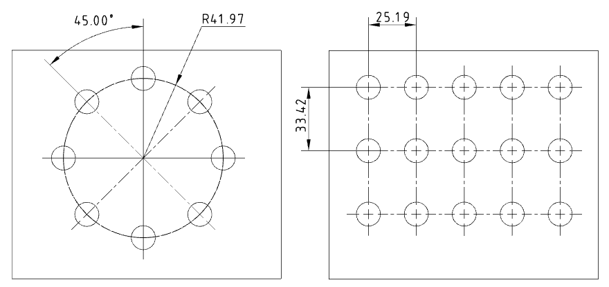
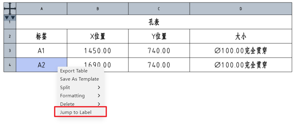
# Hole Table
# Quick Hole Location
By using the hole table, you can quickly confirm the position of a selected hole by right-clicking on the label and navigating directly to it.
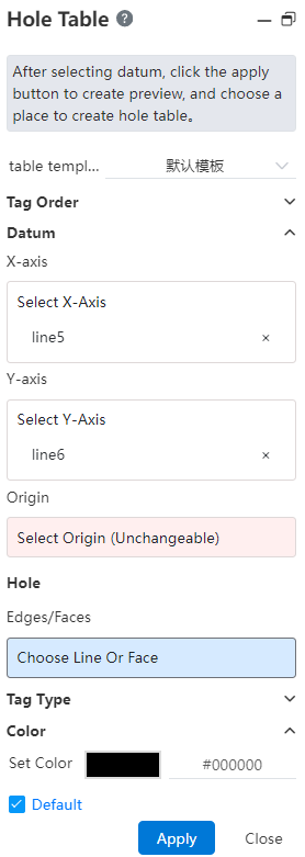
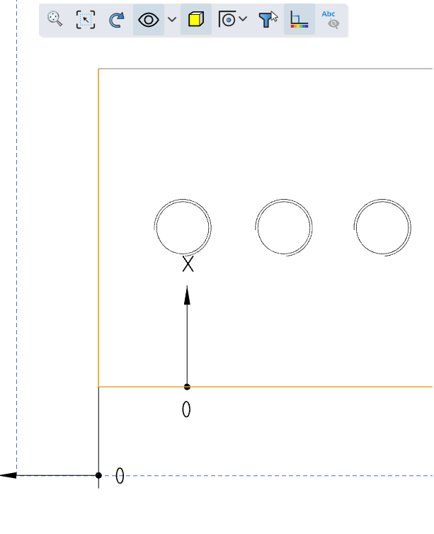
# Simultaneous XY Axis Selection
Supports simultaneous selection of both the X-axis and Y-axis directions. The intersection of the X-axis and Y-axis is automatically set as the origin, and a hole table is generated.
# Coordinate Direction Re-editing
The coordinate direction of the hole table supports re-editing, which facilitates modifying the direction definition of the hole table.
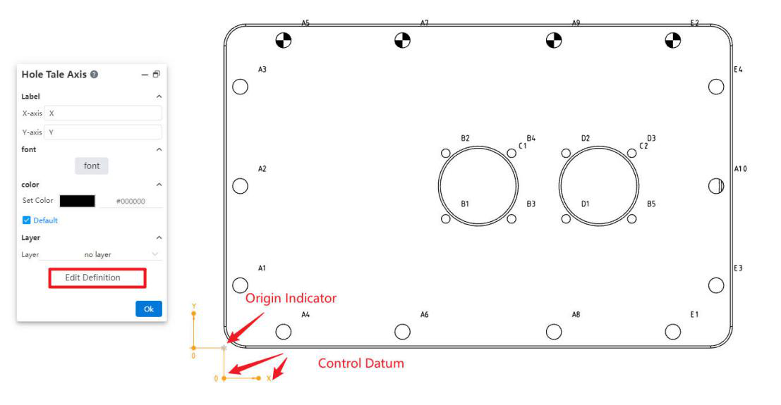
Select the origin indicator to open the "Hole Table Axis" dialog box. In this dialog, you can set the text and font for the X-axis and Y-axis annotations, as well as the associated layer.
Click the "Edit Reference Definition" button in the "Hole Table Axis" dialog box to redefine the coordinate system reference.
When an indicator is selected, dragging it allows you to reverse the X and Y directions. You can also modify the offset distance and direction of the arrow leader from the origin.
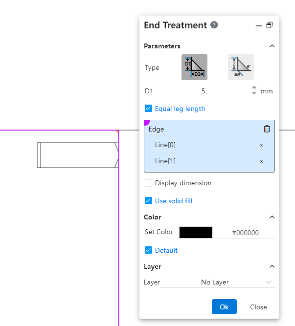
# End Treatment
A new end treatment command has been added to generate markers for annotating the cross-section of welds.
Usage Instructions:
1) Click the "End Treatment" command.
2) Select two intersecting edges.
3) Click in the viewport to generate the end treatment annotation.
Notes: If there are multiple intersection areas for the selected edges, the annotation will be generated where you click in the viewport.
Dialog Box Control Descriptions:
Type: Choose the type of endpoint symbol.
Size: Set the size of the endpoint symbol using parameters D1, D2, Z, and a according to the chosen type.
Equal Support Lengths: Check this box to set D1 = D2.
Edges: Select the two edges on either side of the endpoint symbol.
Show Size: Check this box to display the size dimensions of the endpoint symbol.
Solid Fill: Check this box to fill the interior of the endpoint symbol with a solid color.
Color, Layer: Control the color and layer for the endpoint symbol annotation.
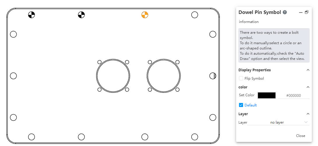
# Dowel Pin Symbol
A new function for adding dowel pin symbols has been added to annotate pins on circular holes.
Usage Instructions:
1) Click the dowel pin symbol  tool in the toolbar to open the command dialog box.
2) Set the color and layer.
3) Manual insertion:Pick the front view of a circle or an arc projection line/sketch line.
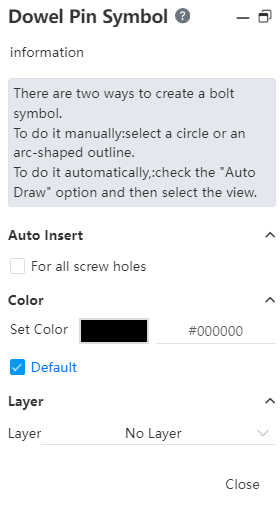
Automatic insertion:Check the option for all blind holes, then pick the view where
you want to create dowel pin symbols.
Notes:
Manual addition allows picking the same edge multiple times to add dowel pin symbols, while automatic addition does not allow adding symbols to edges that already have them.
Once manual insertion begins, it cannot be switched to automatic insertion in the current session. You need to restart the command to select the automatic option.
Pre-selection: Start the dowel pin symbol command after pre-selecting a circle or arc to directly enter the manual insertion process.
Dialog Box Control Descriptions:
For all blind holes: Check this option to enter automatic insertion mode.
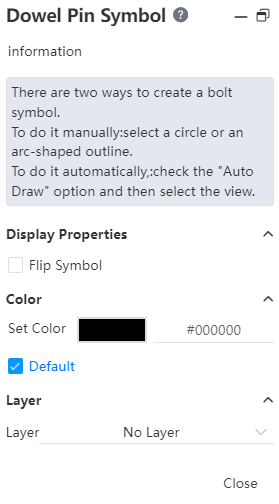
Reverse symbol: Check this option to switch the filled color areas in the symbol (this option is displayed when a dowel pin symbol is selected).
Set color: Set the color for creating the dowel pin symbol.
Default: Check this option to create the dowel pin symbol with the default color.
Layer: Set the layer for the created dowel pin symbol.
← Assembly Sheet Metal →