# Welcome to CrownCAD 2026 R1
CrownCAD 2026 R1 incorporates extensive user feedback to fully meet your design requirements. In terms of usability, we are committed to enhancing user experience; in functionality, we continuously add essential commands that help you quickly complete product design and development tasks.
Main Enhancements:
| Sketch | The sketch dimension tolerance types now include: "Basic," "Fit," "Tolerance and Fit," and "Fit (Show Tolerance Only)." |
| Dimension support for reverse direction, allowing the relative positions of the annotated elements to be swapped. | |
| When generating multiple fillets with the same radius, allow only one fillet annotation to be displayed. | |
| Support automatically adding dimensions and geometric constraints to drawn sketches. | |
| Features | Support stretching/rotating a selected local area of a sketch. |
| The array/mirror command now supports selecting array/mirror features as source features. | |
| Stretch cut now supports removing multiple solids in a single operation. | |
| Added support for creating ANSI Inch (imperial) thread holes. | |
| In the Mirror command, a new "Copy" option has been added to control whether mirroring or symmetry effects are applied. | |
| Surfaces&Curves | Added conic curve command. |
| Added the Intersect command, used to create curves/points at intersection locations. | |
| Added the isoparametric curve command, used to create curves on a surface that align with the isoparametric direction. | |
| Added the spine curve command, used to create curves perpendicular to a sequence of ordered planes or planar curves. | |
| Added the Fair Curve command, used to make existing curves smoother. | |
| Sheet Metal | Edge flange feature supports mirroring. |
| The Stretch Cut command now includes a new "Equal to Thickness" option, allowing you to quickly create cutouts with a consistent thickness matching the sheet metal. | |
| Added rectangular-oval type for edge relief slots. | |
| Assembly | Added cam mate, rack and pinion mate, path mate, and linear/linear coupling. |
| Data Conversion | Support reading MBD annotations from STEP AP242 (.step) files; Support opening CrownCAD models in NX and reading MBD annotations from the original model. |
| Support reading MBD annotations from NX models in CrownCAD. | |
| Added support for automatic conversion when importing assembly compressed packages. | |
| BOM | 【BOM Tools】 supports counting piping BOM information. |
| Apply | Added right-click quick picking feature, supporting rapid selection of edges/lines/faces in models or sketches. |
| Evaluate | Added input diagnostics feature, supporting repair of invalid surfaces and seamless stitching of repaired surfaces into closed ones. |
| Support picking point cloud models for measurement. | |
| Library | New standard component types and improved specifications have been added to the standard parts library. |
| Optimize knowledge base entry and exit. | |
| Motion Analysis | Added motor, force/torque, gravity, and result visualization features. |
| Drawing | Support inserting annotations corresponding to weld features from 3D model files into engineering drawings. |
| Support linear array of existing annotations; support circular array of existing annotations; support setting title block annotations. | |
| Support picking sketch boundaries to fill hatching; meanwhile, expand the range of model faces that can be filled, and support hatching on non-planar model faces. | |
| Support for picking dimension values when creating a datum. | |
| Added the feature to align engineering drawing views, supporting the alignment of auxiliary views, section views, and other views with angles to the engineering drawing views. | |
| Setting | System Settings - Document Properties - Annotations: New options for attachment position, horizontal leader lines, and trailing zero value settings. |
| Support individually setting different fonts for "Part Number, Datum, Geometric Tolerance, Datum Target, Notes, Revision Cloud, Surface Roughness, Welding Symbols" under annotations in system settings. | |
| New configurable options added in Document Properties - Dimension Settings, supporting more detailed customization of dimension styles. | |
| Allow direct renaming of documents within the project document, without having to exit the document and return to the project management interface for renaming. | |
| In Document Properties - View - Section View, a new group for setting arrow styles and line styles has been added. | |
| Piping | Added connection point and route point functions, allowing users to define connection positions for pipework components and specify their placement along the pipeline. |
| Added the grading rule feature, used to create and manage size and attribute rules for pipes, enabling pipe creation based on grading rules. | |
| Supports creating three types of pipes: straight pipes, bent pipes, and flexible hoses. Users don't need to draw pipe profiles. By simply specifying the pipe type, parameters, and grading rules, the system can automatically generate the pipes. | |
| Added piping components library feature, supporting storage and retrieval of piping components. | |
| Support generating piping sub-assemblies within assemblies. | |
| Support controlling the entry and exit of piping sub-assemblies. | |
| Support controlling the activation of piping routes. | |
| Support creating route lines for piping. | |
| Added the command to create hose path lines. | |
| Allow manual addition of bend angles between adjacent route lines. | |
| Supports automatically drawing route lines between two selected connection points. | |
| Allow adding and removing constraints for route lines. | |
| Allows modifying parameters of route lines, such as dimensions, orientation, and bend angles. | |
| Support deleting already drawn route lines. | |
| Support displaying and controlling the default route parameters for piping. | |
| Support routing pipes along a path, placing pipes onto the path. | |
| Allow editing parts placed within piping, and adding modeling features. | |
| Allow editing parts placed within piping, and adding modeling features. | |
| Support editing the dimensions and specifications of already created pipes. | |
| Support breaking a single pipe into two connected pipes. | |
| Support merging two coaxial pipes into a single pipe. | |
| Added filtering options for connection points and route points in the selection filter. After enabling the filter, only corresponding elements can be selected. | |
| New piping-related options added in system settings. |
# Sketch
# Fit with Tolerance
The sketch dimension tolerance types now include: "Basic," "Fit," "Tolerance and Fit," and "Fit (Show Tolerance Only)," enhancing the annotation accuracy and completeness.

The usage is the same as in engineering drawing - dimensions.
# Dimension Reverse Direction
Dimension support for reverse direction, allowing the relative positions of the annotated elements to be swapped.
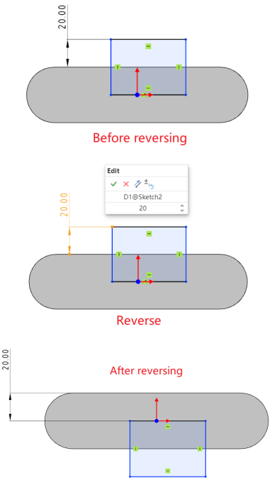
How to use:
1) Click the dimension you want to reverse.
2) Enter a negative value for the dimension, or click the "Reverse" button in the edit window.
3) Click the checkmark √ in the edit dialog box to swap the relative positions of the annotated elements.
How to use:Right-click the dimension and click the "Reverse" option.
# Fillet Optimization
Fillet Optimization: The "Dimension each fillet" option is now set to unchecked by default.
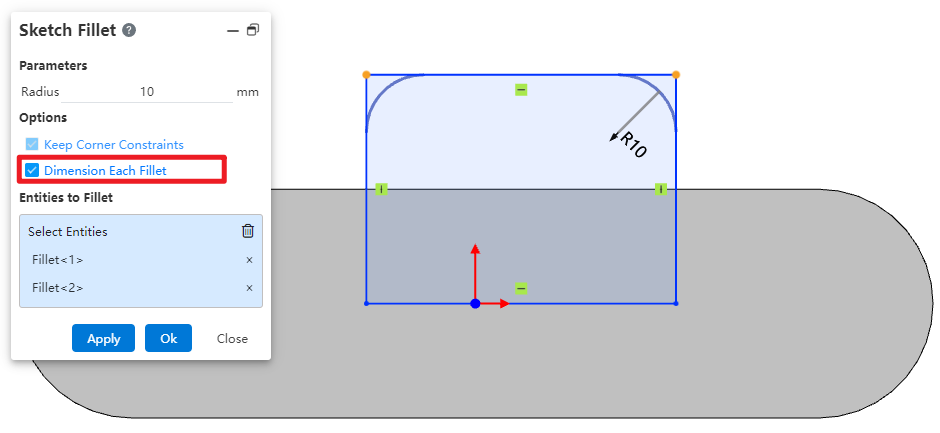
When generating multiple fillets with the same radius, only one fillet is annotated with a radius dimension, while the others are constrained using the "Equal Radius" rule, resulting in a cleaner annotation and more efficient subsequent modifications.
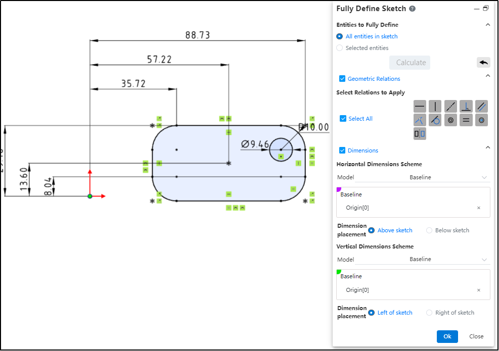
# Fully Define Sketch
Support quick definition and constraint addition for unconstrained sketches.
How to use:
Click this icon , and in the pop-up dialog box, you can determine the elements to be defined, geometric constraint types, dimension constraint mode, dimension placement position, and datum as needed.
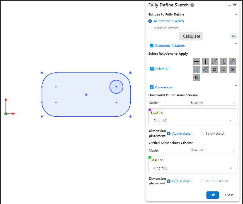
After making your selections, click "Calculate." The sketch will then automatically add constraints according to your requirements.
# Features
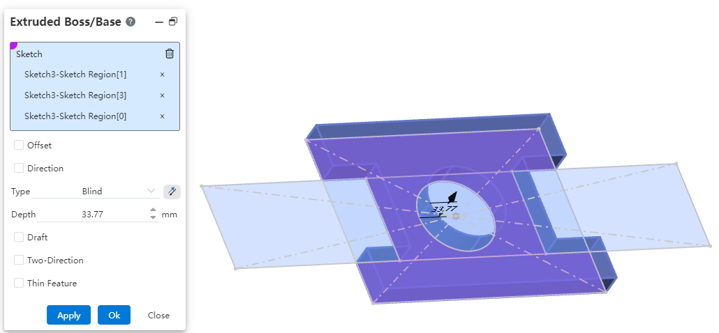
# Stretch/Rotate a selected local area
Support stretching/rotating a selected local area of a sketch.
How to use:
Take the "Extrude Boss/Base" command as an example and open it.
Click on the sketch from which you want to select a local area.
Click on the local region within the sketch that you want to extrude; multiple selections are supported.
Set other parameters, click "OK," and complete the creation of the extrusion feature.
Note:
The commands "Extrude Boss/Base," "Extrude Cut," "Revolve Boss/Base," and "Revolve Cut" all now support local area selection.
Before selecting a local region, click once on the sketch containing the desired area. As you move the mouse over the sketch area in the viewport, the region will be highlighted when it becomes selectable.
# Pattern/Mirror
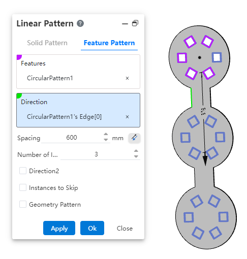
The array/mirror command now supports selecting array/mirror features as source features, enhancing modeling flexibility and efficiency.
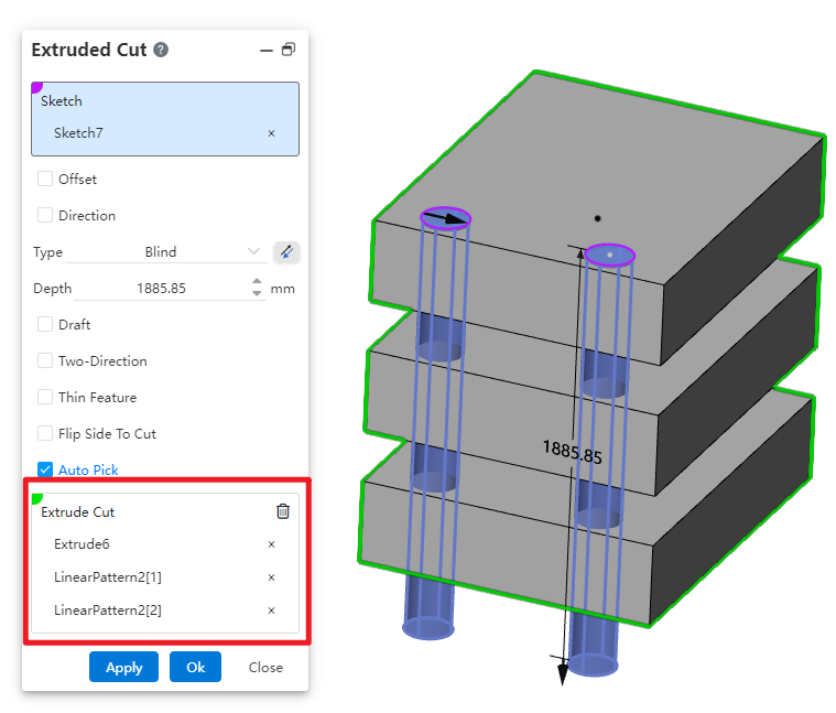
# Extruded Cut
The Stretch Cut feature now supports removing multiple solids in a single operation, significantly improving design efficiency.
How to use:
Open the Stretch Cut command, select the sketch, and set the required parameters.
The system automatically identifies the solids that can be removed based on the parameters, allowing multiple solids to be cut simultaneously.
By unchecking the "Auto Pick" option, you can manually define the solids to be removed.
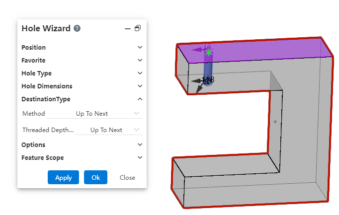
# Hole Wizard
Added support for creating ANSI Inch (imperial) thread holes.
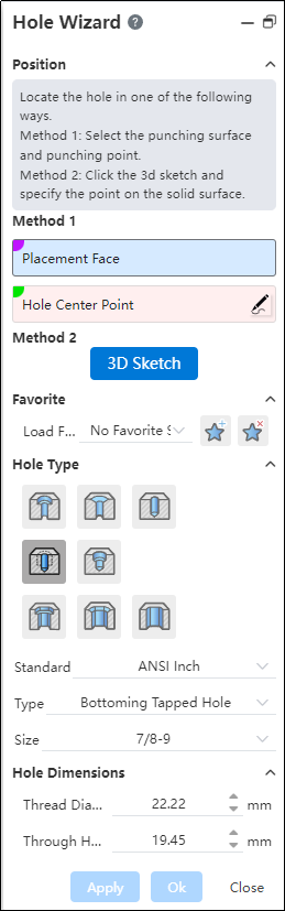
The termination condition now supports forming up to the next face. When this option is selected, there's no need to manually calculate the hole depth—the hole will automatically terminate at the next face, significantly improving design and modeling efficiency.
# Mirror Symmetry
In the Mirror command, a new "Copy" option has been added to control whether mirroring or symmetry effects are applied.
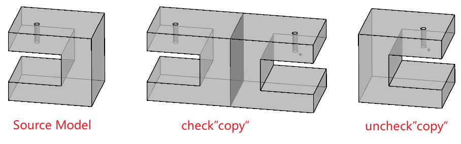
Checked: Generate a new entity as the mirror image.
Unchecked: Perform a symmetric transformation on the existing entity without generating a new one.
# Surfacec/Curves
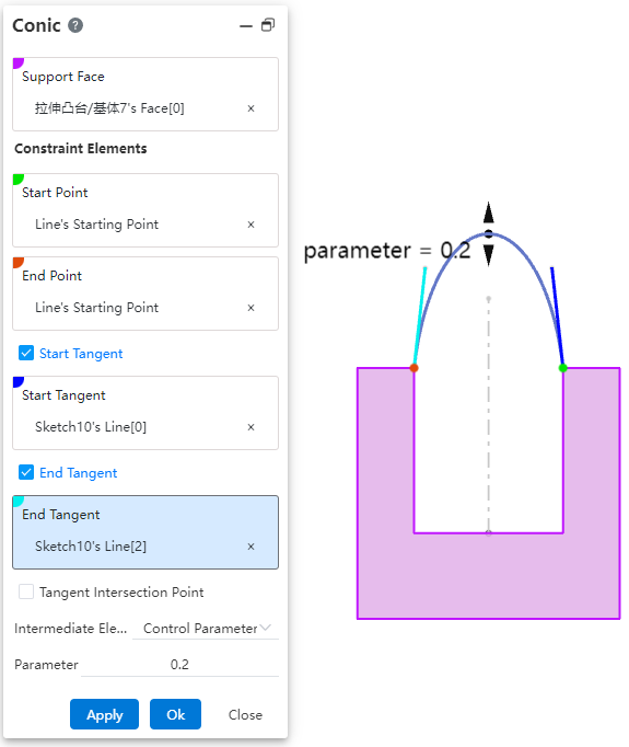
# Conic
Added conic curve command, used to create conic curves.
How to use:
Click the "Conic Curve" command in the "3D Curve" dropdown menu.
Select the required elements: "Support Surface," "Start Point," and "End Point."
Other elements are optional and can be freely selected and combined as needed, such as "Start Tangent," "End Tangent," and "Control Parameter."
If the selected elements can generate a conic curve, the system will display a preview.
If there are too many constraints (over-constrained) or the selected elements cannot form a conic curve, the system will issue a warning.
Click "OK" to complete the creation.
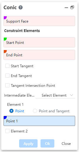
Dialog Box Control Instructions:
Support Surface: The surface on which the conic curve lies must be planar.
Start Point: The starting point of the curve.
End Point: The ending point of the curve.
Start/End Tangent: When checked, allows selecting the tangent at the start/end point.
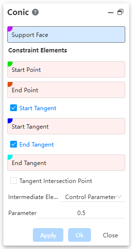
Tangent Intersection Point: When checked, allows selecting the intersection point of tangents; in this case, start/end tangents cannot be selected.
Intermediate Elements: Allows choosing the type of intermediate elements, with options including "Control Parameter" and "Selected Elements".
Control Parameter: By setting a "ratio" value, you can control the shape of the curve.
When the parameter is 0.5, the resulting curve is a parabola.
When the parameter is greater than 0 but less than 0.5, the resulting curve is an ellipse.
When the parameter is greater than 0.5 and less than 1, the generated curve is a hyperbola.
Select Elements: Control the curve shape by selecting through points on the curve.
Point, Point & Tangent: Choose to select only through points, or select both the points and the tangent direction of the curve at those points.
Element 2, Element 3: Check to enable selection of through points 2 and 3 on the curve.
Element illustration:
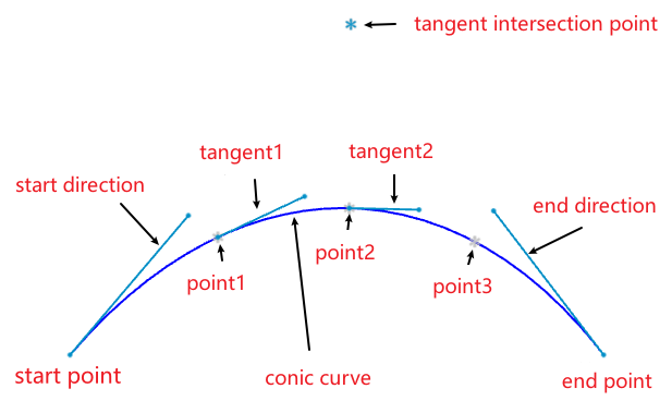
Note:The above figure merely illustrates the correspondence between elements and the curve. When using the command, simply pick some elements to fully constrain the curve, and the curve can be created.
# Intersection
Added the Intersect command, used to create curves/points at intersection locations.
How to use:
Click the "Intersect" command in the "3D Curve" dropdown menu.
Select the first and second elements to be intersected, respectively.
Modify the options as needed.
Click OK to create the intersection curve/point.

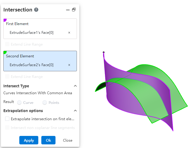
Dialog Box Control Instructions:
First/Second Element: The two elements to be intersected, supporting lines and surfaces.
Extend Linear Intersection to Surfaces: When the intersecting elements do not have an actual intersection region, enabling this option will virtually extend the elements to generate an intersection. This only applies to lines.
Curve Intersection Result with Common Region: When two curves have a completely overlapping segment, this option controls whether the result is the overlapping segment or its endpoint(s).
Extend Intersection Beyond First Element: When two surfaces intersect and the second surface is smaller than the first, enabling this option extends the intersection curve beyond the boundary of the first surface.
Intersect Non-Coplanar Line Segments: For non-coplanar line segments, enabling this option creates the midpoint at the shortest distance between the two lines.
# Isoparamatric Curve
Add a new parameter curve command to create curves on a surface that are aligned with the isoparametric direction.
How to use:
Click the "Isoparametric Curve" command in the "3D Curve" dropdown menu.
Select a surface.
Specify a point on the surface through which the isoparametric curve will pass.
Set the options and parameters as needed.
Click OK to complete the curve creation.
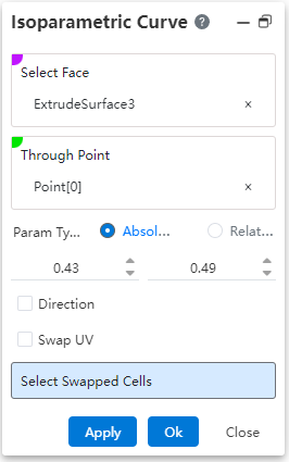
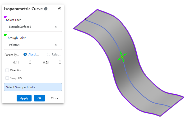
Dialog Box Control Instructions:
Surface: Select the surface on which to create the isoparametric curve.
Through Point: Click on the surface to specify the point that the isoparametric curve will pass through. The direction of the curve is influenced by the mouse movement when specifying this point.
Parameter Type: Controls the type of parameter for the through point's position.
Absolute: The parameter of the through point relative to the absolute origin.
Relative: The parameter of the through point relative to the relative origin. The relative origin defaults to coinciding with the absolute origin. Click the "Reset Origin" button to move the relative origin to the current through point.
Actual Length: Available only when the parameter type is "Relative"; displays the actual distance between the through point and the relative origin.
Direction: Check this option to pick a line to define the UV direction of the surface.
Swap UV Direction: Check this option to swap the UV directions of the surface.
Select Exchanged Face: For a surface composed of multiple patches, select a patch here to change the extension direction of the curve on that patch.

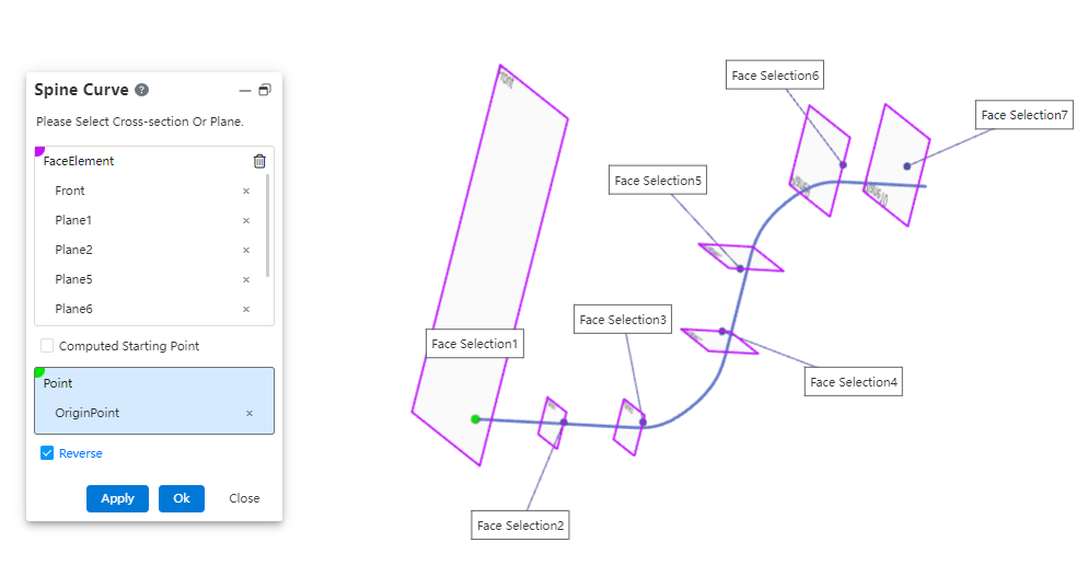
# Spine Curve
Added the "Spine Line" command, used to create curves perpendicular to a sequence of ordered planes or planar curves.
How to use:
Click the "Spine Curve" command in the "3D Curve" dropdown menu.
Select the faces that the spine curve will pass through, in sequence.
Choose the starting point as needed and modify the relevant options.
Click OK to complete the curve creation.
Dialog Box Control Instructions:
Face Elements: Select the planes or sketch profiles that the curve will pass through, ensuring they are picked in the correct sequence.
Computed Start Point: The start point is automatically set based on the first selected element.
Select Start Point: Manually pick a point to define the starting point of the curve.
Reverse Direction: Reverse the direction of the curve from the first face.
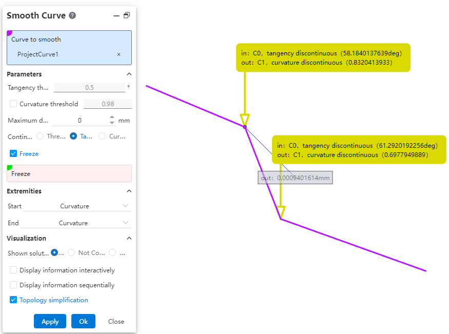
# Smooth Curve
Added the Fair Curve command, used to make existing curves smoother.
How to use:
Click the "Fair Curve" command in the "3D Curve" dropdown menu.
Select the curve you want to smooth.
Set the parameters and options as needed.
Click OK to complete the curve smoothing.
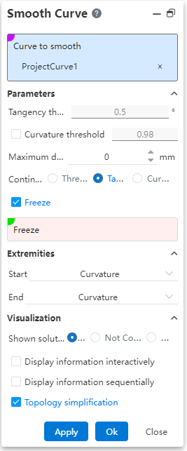
Dialog Box Control Instructions:
Curve to Fair: Used to select the curve that needs to be smoothed.
Tangent Threshold: Sets the tangent discontinuity threshold. The system will smooth the curve within this threshold range. Effective only when the "Continuous Threshold" option is selected.
Curvature Threshold: Sets the curvature discontinuity threshold. The curve will be smoothed within this threshold range. Effective only when "Continuous Threshold" or "Tangent" mode is selected and this option is checked.
Maximum Deviation: Sets the maximum allowable deviation between the original curve and the smoothed curve.
Continuity: Selects the correction mode for smoothing.
Freeze: When checked, allows you to select vertices or edges that should not be smoothed.
Start/End Continuity: Sets the continuity conditions at the start/end points of the smoothed curve and the original curve, respectively.
Displayed Information: Choose what information to display on the smoothed elements in the viewport.
All: Displays all information.
Unresolved: Shows information about discontinuities that were not corrected or preserved.
None: Displays no information.
Interactive Display: When checked, only display information arrows; information appears only when hovering the mouse over the arrow.
Sequential Display: When checked, use "Previous", "Next", or input a sequence number to control which information is displayed.
Topological Simplification: When checked, automatically removes vertices at curvature-continuous locations to reduce the number of segments in the curve.
# Sheet Metal
# Mirrored Edge Flange
Edge flange feature supports mirroring, enabling quick creation of symmetric sheet metal features and improving modeling efficiency.
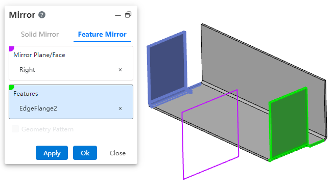
How to use:
Open the Mirror command.
Select the mirror plane.
Select the edge flange feature to be mirrored. Ensure that there is a valid sheet metal edge available at the symmetric position relative to the mirror plane, which can be used to generate the edge flange.
Click OK to complete the feature creation.
# Stretch cut equal to thickness
When extruding to cut a solid, using the "equal to thickness" option allows you to quickly create a cut with a depth consistent with the sheet metal thickness.
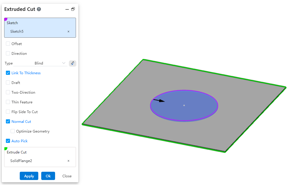
How to use:
Open the document containing the sheet metal body.
Open the Stretch Cut command.
Select the sketch and the feature to be cut.
Check the "Equal to Thickness" option; the depth of the stretch cut will automatically be set to the sheet metal thickness.
Click OK to generate the feature.
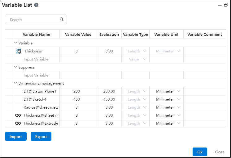
Note:After generating the sheet metal body, a "Thickness" variable with a sheet metal icon will appear in the variable manager, and the thickness of the cut will match the value of this variable.
# Corner Relief
Added rectangular-oval type for edge relief slots, meeting diverse application requirements.
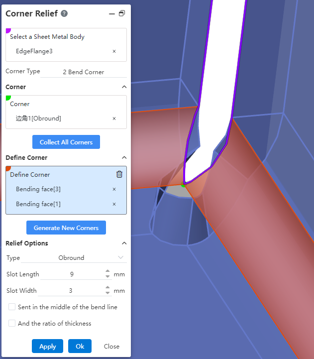
How to use:
Open the "Edge Relief Slot" command.
Select the sheet metal to be modified.
Click "Collect All Corners" to automatically pick corners, or manually select the bend faces on both sides of the corner and then click the "Generate New Corner" button to manually pick the corner.
Select the picked corner in the dialog box.
Change the relief slot type to "Rectangular-Oval".
Set other parameters and options as needed.
Click OK to generate the feature.
Rectangular-Oval Related Options and Parameter Description::
Slot Length/Width: Controls the length and width of the rectangular-oval shape, respectively.
Center on Bend Line: When checked, the slot is positioned at the center of the bend line.
Ratio to Thickness: When checked, a ratio input box is displayed, allowing you to control the slot's length or width based on a proportion relative to the sheet metal thickness.
# Assembly
# Cam
Added a new cam mate type to meet the requirements of various scenarios.This fit ensures that the cam maintains the correct motion and position of the follower during operation.
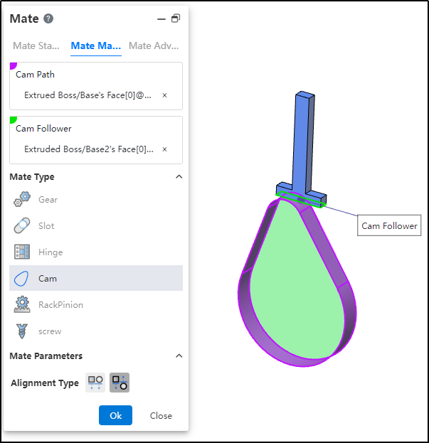
How to use:
After inserting the cam and follower parts, click the "Mate - Mechanical - Cam" command.
Select the cam groove, pick the element; successful selection will be highlighted in purple.
Select the cam follower, pick the element; successful selection will be highlighted in green.
In the "Alignment Type" section, choose the desired alignment method.
Click OK to generate the feature.
Note: The elements that can be picked for the cam groove and cam follower are points and faces. The profile sketch of the cam groove must form a closed loop, and there must be a tangent constraint between two connected lines. If features are added to the face used as the cam groove, breaking its continuity, the face cannot be picked as a cam groove element.
# RackPinion
Added a new rack and pinion mate type to meet the requirements of various scenarios. This mate enables the gear part to rotate through the linear translation of the rack part.
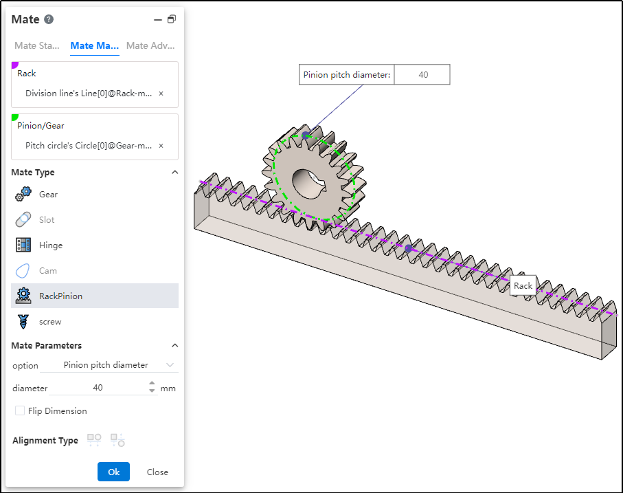
How to use:
After inserting the gear and rack parts, click the "Mate - Mechanical - Rack and Pinion" command.
Select the rack and pick the element (commonly the rack pitch line); successful selection will be highlighted in purple.
Select the pinion gear and pick the element (commonly the gear pitch circle); successful selection will be highlighted in green.
In the options, check either "Pinion Pitch Diameter" or "Rack Stroke/Revolution," and the system will automatically calculate the value. Additionally, users can manually set the parameters.
Decide whether to check "Reverse Dimension" based on your needs.
Click OK to generate the feature.
Note: Both rack and pinion support curves, cylindrical surfaces, and arc surfaces as pickable elements. This mating type can also be applied without drawing a gear, and can be achieved using linear edges, circular edges, and other features.
Dialog Box Control Instructions:
Pinion Pitch Diameter: The pitch circle diameter of the gear.
Rack Stroke/Revolution: π × the pitch circle diameter of the meshing gear.
Reverse Dimension: By default, the gear rotates clockwise while the rack translates in the negative direction. When the "Reverse Dimension" option is checked, the gear still rotates clockwise, but the rack now translates in the positive direction.
# Path Mate
A new "Path Mate" type has been added to advanced mates, meeting requirements across various scenarios. The path mate constrains selected points on components to a path, and allows users to define deviations, swaying, and other behaviors as the component travels along the path.
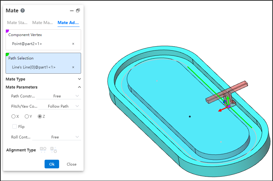
How to use:
After inserting the parts, click the "Mate - Advanced - Path Mate" command.
Select the part vertex and pick the point element.
Select the path and pick the sketch profile, solid edge, or curve.
Choose the path constraint type based on your needs.
Choose the pitch/yaw control type based on your needs.
Choose the roll control type based on your needs.
Click OK to generate the feature.
Dialog Box Control Instructions:
Path Constraint: Choose how the component moves along the path.
Free: The component can move freely along the path.
Distance along Path: The component is fixed at a specific distance along the path and cannot move, but can rotate freely around the vertex.
Percentage along Path: The component is fixed at a specific percentage along the path and cannot move, but can rotate freely around the vertex.
Pitch/Yaw Control: Choose the pitch angle and orientation of the component as it moves along the path.
Free: The component can freely adjust its pitch while moving along the path.
Follow Path: By selecting a 3D coordinate direction, the component maintains a consistent pitch orientation during movement.
Roll Control: Choose the roll angle and direction of the component as it moves along the path.
Free: The component can rotate freely while moving along the path.
Up Vector: Ensures the rotational orientation of the component during movement by selecting a constraint element and a three-axis direction.
# Liner/Liner Coupler
A new "Linear/Linear Coupling" mate type has been added to advanced mates, meeting requirements across various scenarios. By establishing a geometric relationship between the translation of one component and the translation of another, motion can be defined for each component relative to the ground or a reference component.
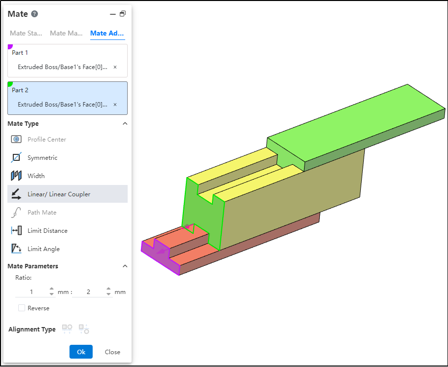
How to use:
After inserting the parts, click the "Mate - Advanced - Linear/Linear Coupling" command.
Select Part 1 and pick the element; this element serves as the reference during linear movement.
Select Part 2 and pick the element; this element establishes a proportional distance relationship with the reference element during linear movement.
Set the ratio.
Decide whether to check "Reverse" based on your needs.
Click OK to generate the feature.
Note: The ratio indicates that when the first component moves a certain distance, the second component moves a corresponding distance based on the predefined ratio relative to the reference. For example, a ratio of 1:2 means that when the first component moves 1 mm, the second component moves 2 mm relative to the reference element.
# Data Conversion
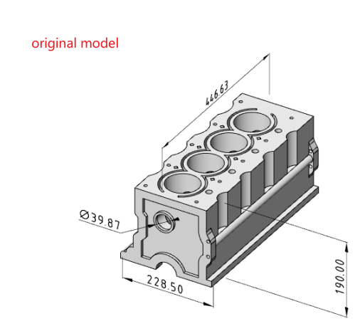
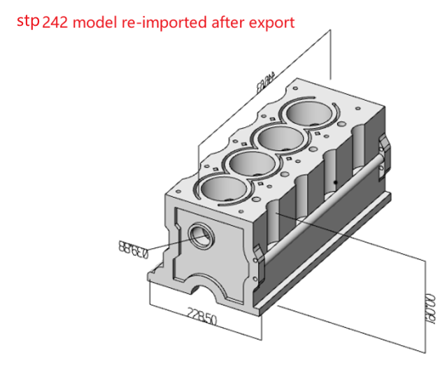
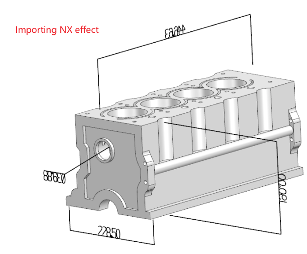
# stp242 Import/Export
The STEP AP242 file exported from CrownCAD can be re-imported into CrownCAD or opened using NX, and it also supports reading MBD annotations from the original model.
# NX PMI Reading
Support reading all PMI annotations from NX models.
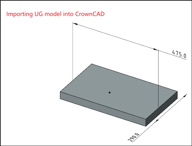
# Automatic Conversion
When importing an assembly zip package, automatic conversion is supported.
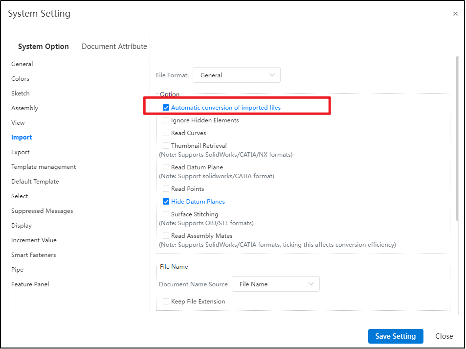
After checking the "Auto-convert imported files" option in the settings, all documents in the compressed package will be automatically extracted and converted.
# Apply
# Right-click to select loop/chains/tangency/midpoint
Added right-click quick picking feature, supporting rapid selection of edges/lines/faces in models or sketches, simplifying the modeling process and improving design efficiency.
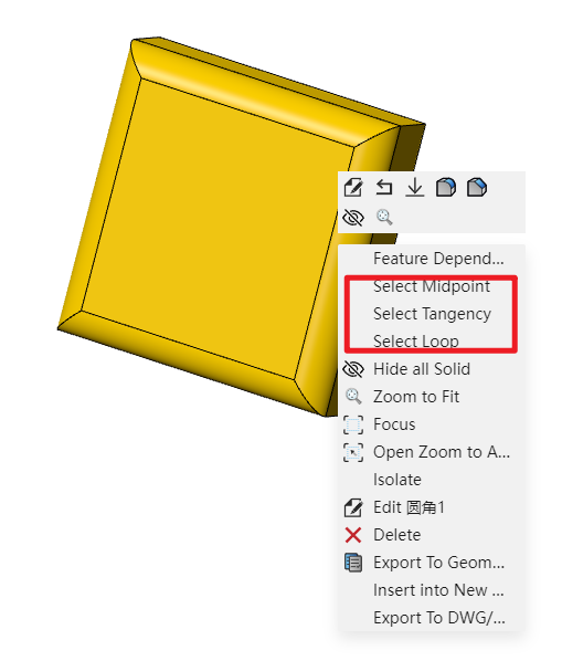
When using, right-click on the element to select the desired quick pick options from the pop-up toolbar.
# Evaluate
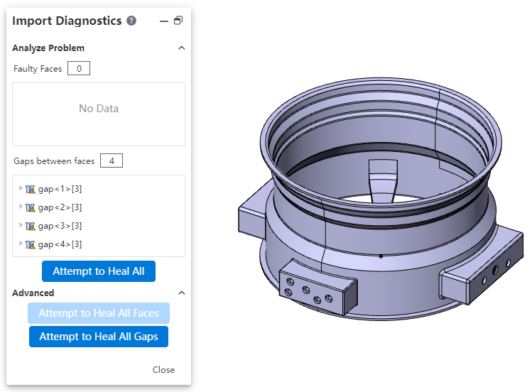
# Import Diagnostics
Added input diagnostics feature in the evaluation module, supporting repair of invalid surfaces and seamless stitching of repaired surfaces into closed ones.
How to use:
Import the model and click Evaluate - Input Diagnostics.
The system will automatically analyze defective surfaces and gaps, displaying them one by one.
Click Try to Heal All Surfaces and Try to Heal All Gaps—the system will automatically repair the invalid surfaces and fill the gaps.
Note: Input diagnostics can only be initiated when importing external formats.
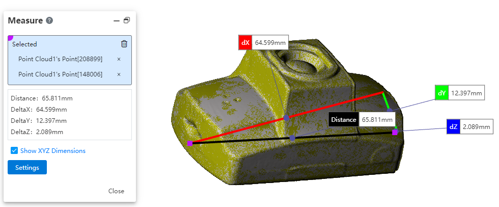
# Measure
The measurement feature supports picking point cloud models for measurement.
# Motion Analysis
# Motor
Support adding motors to drive components to move linearly or rotate.

How to use:
Open the Motion analysis and select the Motor
 command.
Choose the motor type according to your requirements.
Select the position where the motor will be added.
Choose the reference direction for motor rotation.
Select the component(s) that will move relatively during motor rotation.
Select the component(s) that will move relatively during motor rotation.
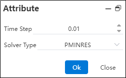
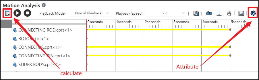
Click on the Motion Study Properties in the upper-right corner, select the solver, and then click Calculate in the upper-left corner.

After successful calculation, click "Play"
 to view the motion process.
Click the "Save" button at the bottom-right corner to save the motion study results.
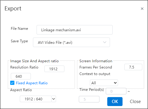
Click "Export"
 to export video files in different formats as needed.
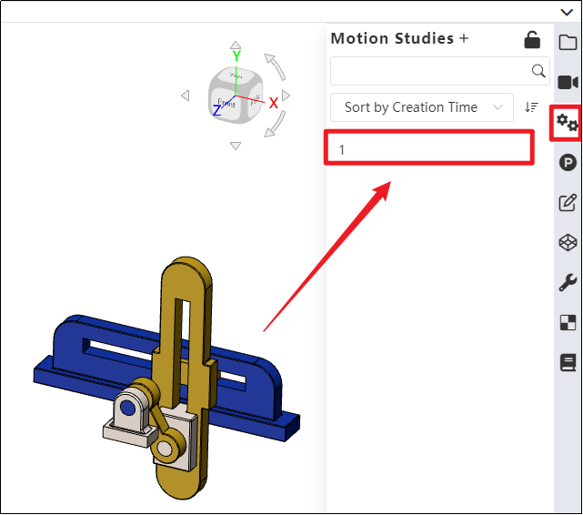
- Click on the Motion analysis list in the right sidebar to find the saved motion study.
Note: Currently, only constant-speed rotation or linear movement is supported. In future versions, variable speed, intermittent motion, and other motion types will be supported, which can be defined using functions and other methods.
Dialog Box Control Instructions:
Motor Type: Currently supports rotary motors and linear motors, with rotary motor as the default. Path motors will be supported in future versions.
Motor Position: The driven component that rotates or moves under the influence of the motor.
Motor Direction: The reference direction for motor motion. Users can choose clockwise or counterclockwise rotation as needed.
Motor Direction: The reference direction for motor motion. Users can choose clockwise or counterclockwise rotation as needed.
Speed: Set the motor's motion speed. Default speed is 100 RPM for rotary motors and 10 mm/s for linear motors. Input range: [0, 1e5].
Time Step: The time interval for each calculation cycle used by the solver.
Solver Type: Different solvers with various computational methods and kernels.
# Force/Torque
Support adding forces/torques to components to simulate their motion under loading conditions.

How to use:
Open the Motion analysis and select the Force
 command.
Choose the type of external load to be applied according to your requirements.
Select the position and direction where the external load will be applied, as needed.
Choose whether the load is a single force or an interaction force, as required.
Set the force function type and the magnitude of the load. Click OK.
Click on the Motion Study Properties in the upper-right corner, select the solver, and then click Calculate in the upper-left corn.

After successful calculation, click "Play"
to view the motion process.Click the "Save" button at the bottom-right corner to save the motion study results.
Click "Export"
to export video files in different formats as needed.
Dialog Box Control Instructions:
Force Type: Choose between force or torque based on your requirements.
Position: Select the location where the external load will be applied, according to your needs.
Direction: After selecting the position, the system automatically displays the load direction using an arrow. You can adjust the load’s positive or negative direction as needed, or re-pick a geometric element to define the load direction.
Direction Type: Choose whether the load is a single-direction force or an interaction force based on your requirements. (External loads are typically single-direction forces; springs are interaction forces.)
Application Point: Select the point where the load will be applied, according to your needs.
Force Function: Currently supports constant, step, and harmonic force functions. Future versions will support segment, data point, expression, and custom function types. After selecting the function type, enter the load magnitude.
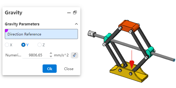
# Gravity
Support adding gravity to the entire assembly to simulate the effect of gravity on the motion simulation.
How to use:
Open the Motion analysis and click the Gravity
 command.
You can define the direction of gravitational acceleration using a 3D coordinate system, or select a geometric element as needed to define the direction.
Enter the acceleration value.
Click OK.
Note: Gravity is typically used in conjunction with motors, forces/torques. When defining gravity using a 3D coordinate system, there's no need to pick geometric elements.
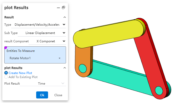
# Plot Results
Supports analyzing the motion process of Motion through diagrammatic calculation.

How to use:
Open Motion analysis and click on Result Diagram
 .
.Select the category to be analyzed according to your needs.
Determine the subcategory for analysis based on your requirements.
Specify the result component to be analyzed.
Pick a face, edge, vertex, or mate of the component.
Pick a face, edge, vertex, or mate of the component.
Select the dependent variable for the diagram result.
Click OK to generate the result diagram.
Note: Currently, only result diagrams for linear displacement, angular displacement, motor force, motor torque, etc., are supported. Support for all result diagrams will be gradually added in the future.
Dialog Box Control Instructions:
Category: Select either "Displacement/Velocity/Acceleration" or "Force".
Subcategory: The subcategories for "Displacement/Velocity/Acceleration" are "Linear Displacement" and "Angular Displacement"; the subcategories for "Force" are "Motor Force" and "Motor Torque".
Result Component: Specify the direction of the result component.
X/Y/Z Components: Represents the component values along the X/Y/Z axes.
Magnitude: The magnitude of the result can be resolved relative to the global coordinate system.
Select a face, edge, vertex, or mate of the component: Define the object for result diagram calculation.
Diagram Output Options: Specify the output settings for the result diagram.
Generate New Diagram: Creates a new diagram independent of existing results in the motion study.
Add to Existing Diagram: Adds the calculation results to an existing diagram, generating a multi-Y-axis curve.
Diagram Result Independent Variable: Specify the X-axis variable for the diagram result. Options include time, frame number, or a new result.
# Drawing
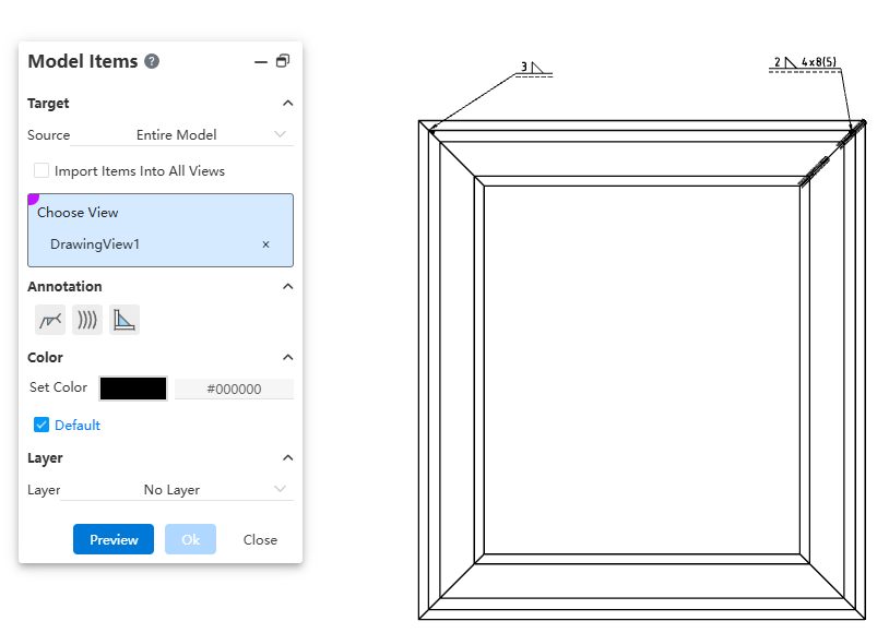
# Model Items
Added the model project feature, supporting the insertion of annotations corresponding to weld features from 3D model files into engineering drawings.
Dialog Box Control Instructions:
Source: Controls the source of the project. Options include "Selected Features," "Entire Model," "Selected Components," or "Assembly Only."
Insert Project into All Views: Controls whether the project is inserted into all views on the drawing. When selected, you can insert the model project into all views without manually selecting target views.
Target View: Controls which view the model project is inserted into. The project will be inserted into the selected view.
Annotation Type: Controls the type of annotation to be inserted. By default, none are selected.
Color/Layer: Sets the color and layer for the inserted project.
How to use:
Activate the Model Project command.
Set the target for the project: choose the source and the target view where the project will be inserted.
Select the annotation types to insert, including welding symbols, worms (caterpillar), and end treatments.
Set the layer and color for the inserted project.
Click Preview to display the insertion effect of the configured model project.
Click OK to complete the insertion of the model project.
Note:
- After viewing the preview, any changes to settings will cause the preview to disappear. You must manually click the Preview button again to recalculate and display the updated preview.
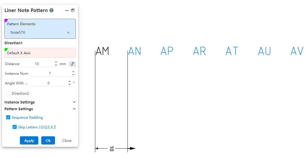
# Liner Note Pattern
Added the linear array annotation command, which supports linear arraying existing annotations. This allows for quickly generating array annotations at specified locations, effectively improving drawing efficiency.

How to use:
Open the linear array annotation command.
Select the annotations to be arrayed.
Set the array direction parameters.
Set whether to array only the source or skip instances.
Set whether to apply sequence filling.
Click Apply/OK to complete the creation of the array annotation.
Dialog Box Control Instructions:
Elements to Array: Required. Select the annotation elements in the current drawing to be arrayed. Multiple selection and box selection are supported.
Direction 1 / Direction 2: Control the direction of the annotation array. Default is X-axis/Y-axis direction. You can manually set the array direction by picking two points or line elements. Direction 1 is required; Direction 2 can be optionally set, default is unchecked.
Distance: Enter the spacing between instances. The reverse button can change the array direction.
Number of Instances: Enter the number of instances.
Angle with X-axis: When no element is picked for direction, the array direction is set by rotating the current sketch’s X-axis counterclockwise by the specified angle.
Array Only Source: Default is unchecked. When checked, only two columns along the two straight-line directions are arrayed.
Skip Instances: Default is unchecked. When checked, select the annotations to skip in the array preview; these annotations will not be generated.
Sequence Fill: Controls whether sequence filling is applied to the selected annotations. Sequence filling only supports annotations with pure letters or pure numbers in a single direction, such as "AA" or "1". Default is unchecked; when checked, sequence filling is automatically applied.
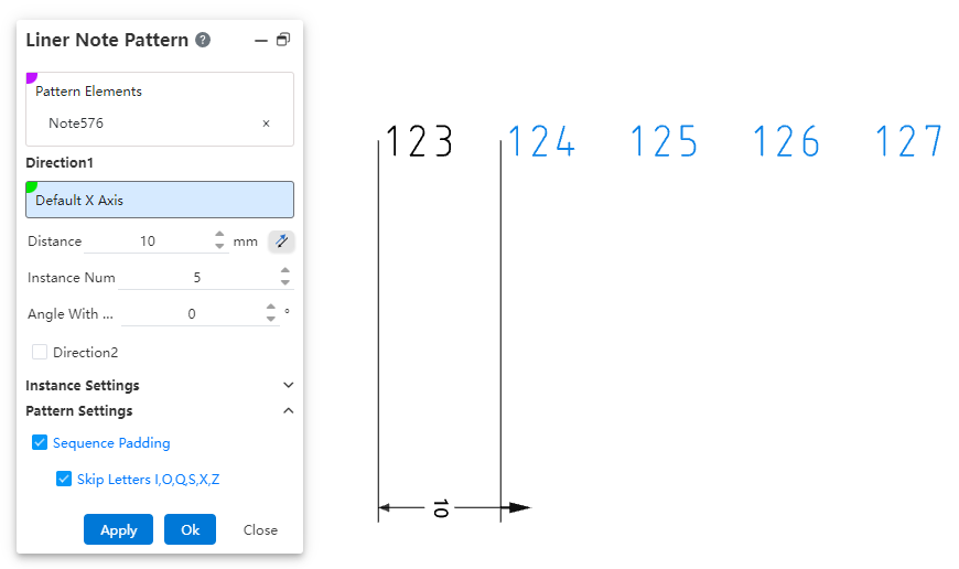
- Skip letters I, O, Q, S, X, Z: This option appears only when "Sequence Fill" is checked, and is selected by default. When checked, sequence filling will automatically skip the letters I, O, Q, S, X, and Z.
Note:
- The array source annotation and each of the generated annotations in the array are independent of one another. Each annotation is a standalone, independent entity without positional constraints, allowing individual editing, deletion, and repositioning.
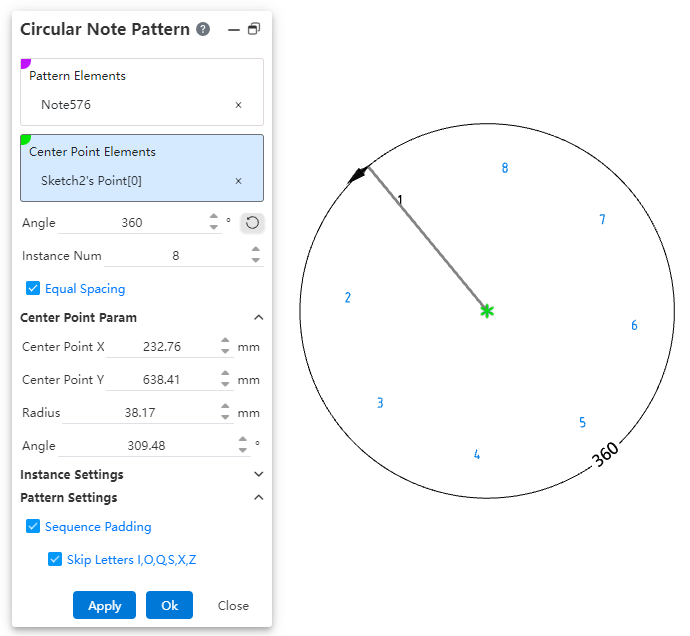
# Circular Note Pattern
Added the circular array annotation command, which supports circular arraying existing annotations. This allows for quickly generating array annotations at specified locations, effectively improving drawing efficiency.
How to use:
Open the circular array annotation command.
Select the annotations to be arrayed.
Pick the center point of the array.
Set the array angle, number of instances, and center point parameters.
Set whether to array only the source or skip instances.
Set whether to apply sequence filling.
Click Apply/OK to complete the creation of the array annotation.
Dialog Box Control Instructions:
Elements to Array: Required. Select the annotation elements in the current drawing to be arrayed. Multiple selection and box selection are supported.
Center Point: Controls the center point of the annotation array. Default is the drawing origin. Supports manually setting the array center point by picking a point element.
Angle: Controls the array angle, used in conjunction with the "Equal Spacing" option. Supports dragging the handle to adjust the angle.
Number of Instances: Controls the number of array instances.
Equal Spacing: Controls whether the input angle represents the total array angle or the spacing angle.
Checked (Default): The input angle is the total array angle.
Unchecked: The input angle is the spacing angle between array instances.
Center Point X/Y Coordinates: Controls the X/Y coordinates of the center point relative to the drawing origin. Displays the current center point coordinates by default and supports manual input, including positive, negative numbers, and zero.
Radius: Controls the distance from the center point to the annotation source. Input range: ≥ 0.00001.
Angle: Controls the angle between the line from the center point to the annotation source and the X-axis of the drawing. Supported input range: [0°, 360°].
Array Only Source: Default is unchecked. When checked, only two columns along the two straight-line directions are arrayed.
Skip Instances: Default is unchecked. When checked, select the annotations to skip in the array preview; these annotations will not be generated.
Sequence Fill: Controls whether sequence filling is applied to the selected annotations. Sequence filling only supports annotations with pure letters or pure numbers in a single direction, such as "AA" or "1". Default is unchecked; when checked, sequence filling is automatically applied.
Skip Letters I, O, Q, S, X, Z: This option appears only when "Sequence Fill" is checked and is selected by default. When checked, sequence filling will automatically skip the letters I, O, Q, S, X, and Z.
Note:
- The array source annotation and each of the generated annotations in the array are independent of one another. Each annotation is a standalone, independent entity without positional constraints, allowing individual editing, deletion, and repositioning.
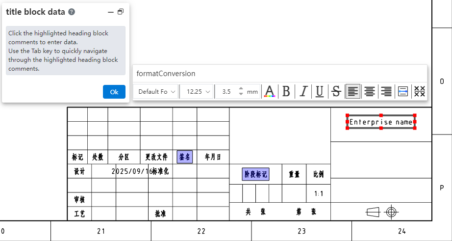
# Title Block
Added the "Title Block Field" command, which supports setting title block annotations, enabling quick editing of title block text or modifying annotations within the drawing format without having to enter the drawing format.
How to use:
1) Enter the editing drawing format mode and click on the "Title Block Field" command to activate it.
2) Drag the rectangular hotspot area to adjust its size and position.
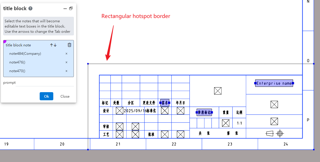
3) In the viewport, click on the annotation to set it as a title block annotation, and configure the prompt as needed.
4) Click OK to complete the creation of the title block feature.
5) Enter the editing state for title block data by double-clicking the hotspot area, right-clicking the title block feature in the view panel and selecting "Insert Title Block Data," or right-clicking the hotspot area and selecting "Insert Title Block Data."
6) Click any title block annotation to edit the selected title block annotation.
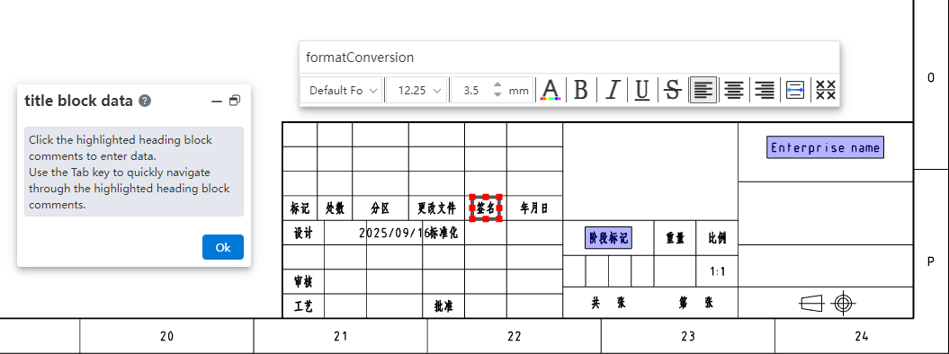
7) Press the Tab key to switch to the next title block annotation, or directly click on the title block annotation you want to modify to edit multiple title block annotations consecutively.
8) Click the OK button in the dialog box to complete this title block annotation editing session.
# Region Hatch Fill
The region hatch command has been enhanced with additional hatch types and improved capabilities. It now supports picking sketch boundaries to fill hatching, and the range of model faces that can be filled has been expanded to include non-planar model faces.
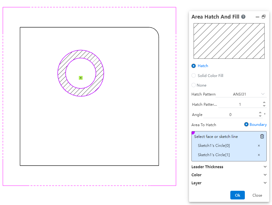
How to use:
1) Open the region hatch command.
2) Select a single closed sketch boundary or a non-planar model face projection area.
3) Click OK to fill the region hatch within the closed sketch profile or selected model face area.
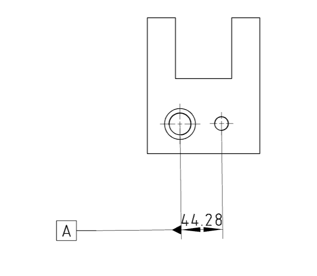
# Datum
Added the ability to pick dimension values when creating a datum. The datum created by snapping to dimension values is automatically merged with the dimension and aligned with the dimension line.
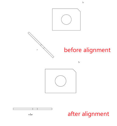
# Align Engineering Drawing Views
Added the feature to align engineering drawing views, supporting the alignment of auxiliary views, section views, and other views with angles to the engineering drawing views.
How to use:
1) Right-click the view you want to align.
2) Click on the "Align Engineering Drawing Views" dropdown menu, and select "Counterclockwise/ Clockwise Horizontal Alignment" to rotate the view to a horizontal alignment angle in the counterclockwise/clockwise direction.
3) Right-click the view that has been aligned.
4) Click on the "Align Engineering Drawing Views" dropdown menu, and select "Default Alignment" to restore the view to its default angle as it was when originally created.
Note:
The "Align Engineering Drawing Views" dropdown option is displayed only when right-clicking a view to set alignment.
Alignment can only be applied to section views, auxiliary views, and removed section views.
# Setting
# Annotation
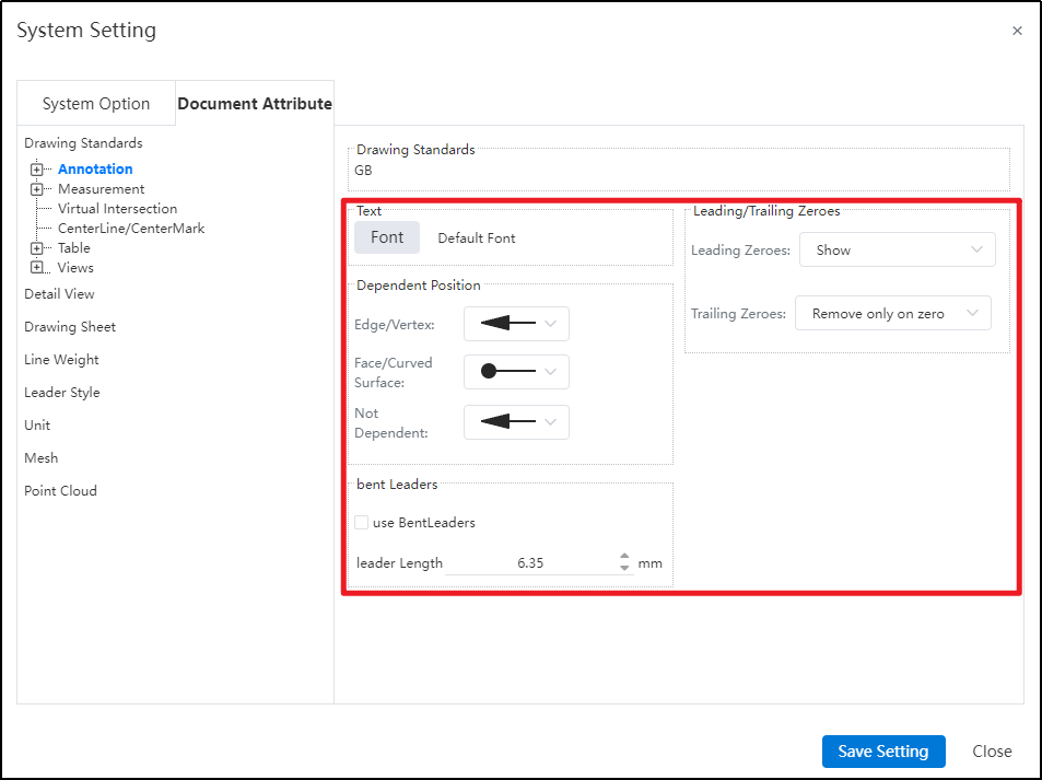
System Settings - Document Properties - Annotations: New options for attachment position, horizontal leader lines, and trailing zero value settings.
Note:
Attachment Position: Supports setting different default arrow styles for creation based on attachment position in document properties.
Horizontal Leader Lines: Controls whether horizontal leader lines are used by default and allows setting the leader line length.
Leading/Trailing Zero Values: Supports configuring the display format for "leading zeros" and "trailing zeros," controlling how values obtained through associated properties (e.g., mass, length) are displayed in annotations.
# Font
Added font settings, supporting individual font configuration for "Part Number, Datum, Geometric Tolerance, Datum Target, Notes, Revision Cloud, Surface Roughness, Welding Symbols" under annotations in system settings.
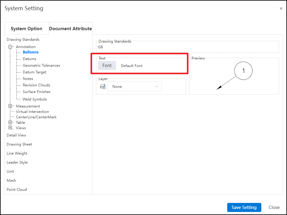
Note: Support individual font configuration for different annotation types under annotations, with font style settings displayed as images in the preview.
# Measurement
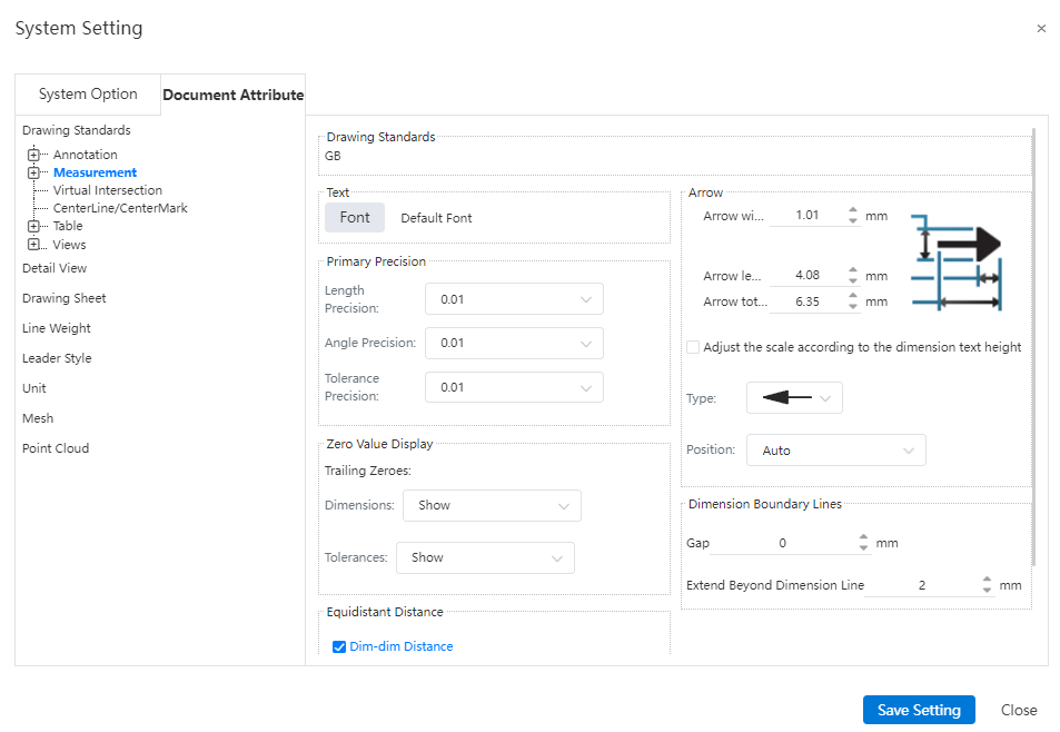
In the Document Properties - Dimension Settings, new configurable options have been added, enabling more detailed customization of dimension styles.
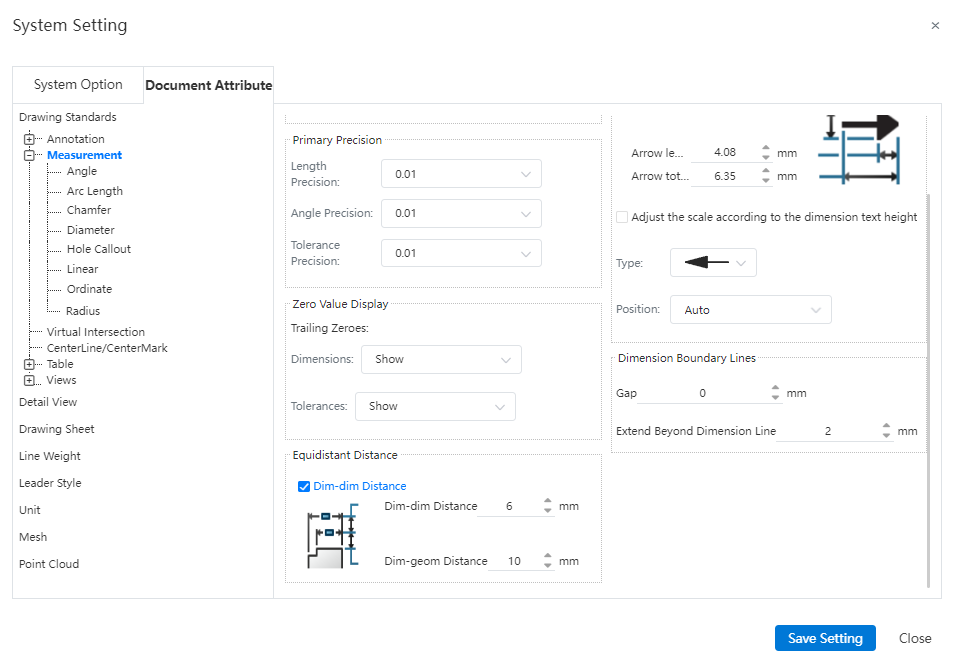
Note:
Arrow size: Supports setting the style of dimension arrow size, allowing individual adjustments for arrow width, head length, and head plus leader length (leader extending beyond the arrow). It also allows setting the default arrow type and default arrow position when creating dimensions.
Trailing Zeros: Support for setting the display effect of trailing zeros in "Document Properties - Dimensions" and "Document Properties - Dimensions - Angles".
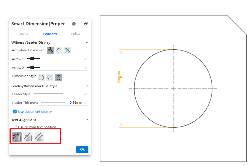
Text Position: Supports setting the default text position for corresponding dimensions in "Document Properties - Dimensions - Angles, Arc Length, Chamfer (Leader Only), Diameter, Radius (Leader Only), Linear". Controls the default state of the "Custom Text Position" option in the respective dimension commands.
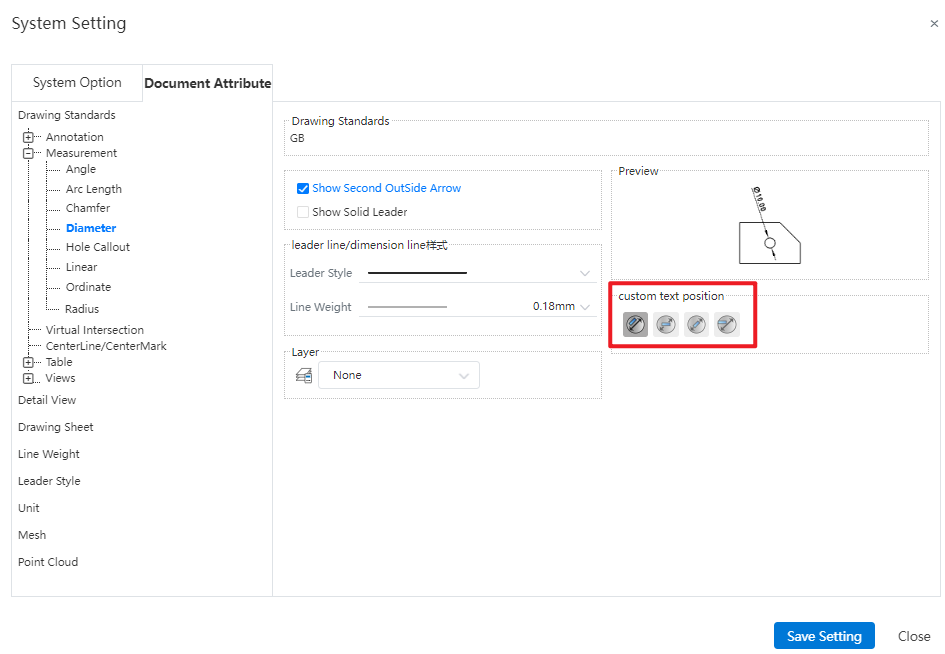
- Leader/Dimension Line Style: Supports setting the line style and line width of leaders for corresponding dimension annotations in "Document Properties - Dimensions - Angles, Arc Length, Chamfer (Leader Only), Diameter, Radius (Leader Only), Linear".
# Rename
Allow direct renaming of documents within the project document, without having to exit the document and return to the project management interface for renaming.
How to use:
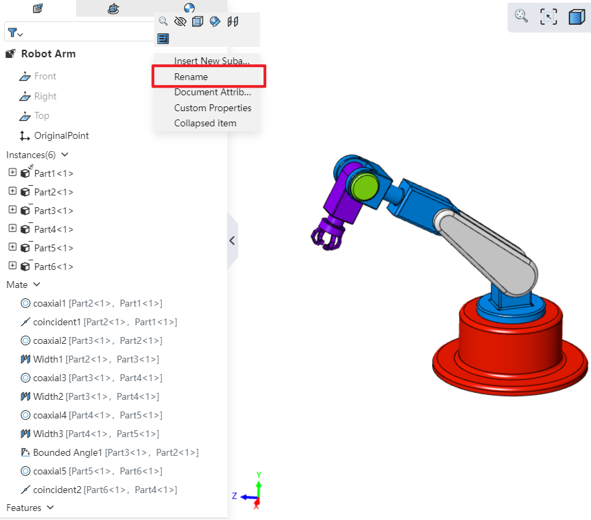
Open "System Settings - Feature Panel" and check "Allow renaming parts via Feature Panel."
In the opened project document, right-click the document name and select "Rename" to rename it.
Note: In part documents, the corresponding command is "Rename Part"; in assembly documents, if renaming the entire assembly, the corresponding command is "Rename Assembly". If renaming an inserted instance, the corresponding command is "Rename"; in drawing documents, the corresponding command is "Rename Drawing".
# View-Section View
In Document Properties - View - Section View, a new group for setting arrow styles and line styles has been added.
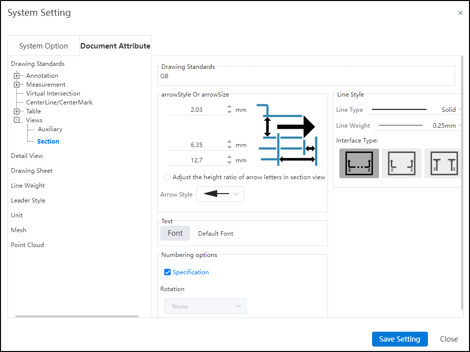
Dialog Box Control Instructions:
Arrow Style and Size:
Arrow Size: Controls the height, width, and total length of section line arrows individually.
Proportional Adjustment Based on Section View Label Font Height: Not checked by default. When selected, the arrow size automatically adjusts proportionally based on the font size of the section view label, and manual input is not allowed.
Arrow Style: Controls the default style of section line arrows.
Line Style:
Line Type: Controls the default line style for section lines.
Line Thickness: Controls the default thickness of section lines.
Connection Style: Allows setting the connection style for section lines. The default is standard with connection. You can choose among three types: standard with connection, standard without connection, and alternative without connection.

# Piping
# Piping component design
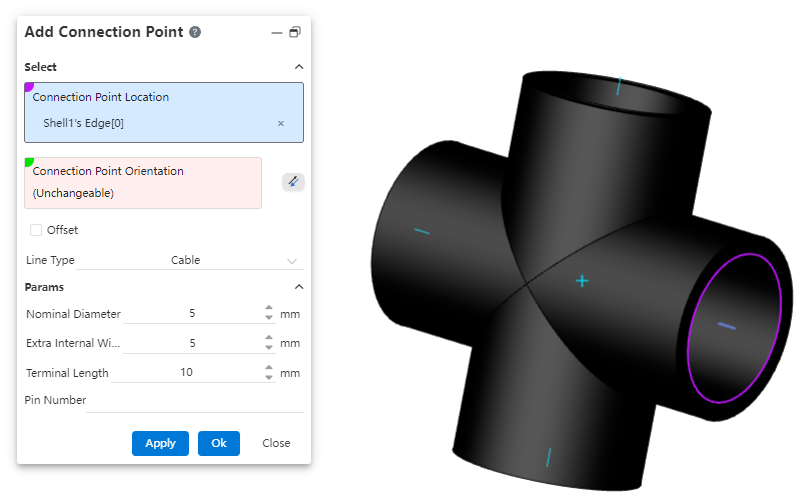
# Add Connection Point
A connection point is a feature displayed as a directional axis, used to control the start/end point of a pipe and also to manage connections between piping components.
How to use:
Create a new part, complete the sketch, then click on "Path - Connection Point."
Select the geometric elements to define the connection point's position.
If the selected geometric element is a circular edge or a plane, the system defaults the connection point direction to be perpendicular to the plane. You can click the reverse icon to change the orientation. If the selected element is a sketch line/point or a model edge, the connection point direction must be manually defined by selecting a geometric element.
Determine whether the connection point needs to be offset based on your requirements.
Select the piping type, and determine whether to enable the grade rule based on your requirements.
Set the relevant parameters.
Dialog Box Control Instructions:
Connection Point Position: Only a single geometric element can be selected. Supported elements for selection: origin, sketch point, endpoint of an edge/sketch line, circular edge, or circular plane as the connection point position.
Connection Point Direction: If the selected connection point position does not require a specified direction, the system will automatically fill in the direction. If a direction needs to be defined, the user must manually pick a geometric element to determine the direction.
Offset: Controls whether the connection point starts from an offset along the connection point direction from the initial position. By default, this is unchecked.
Category: Options include "Piping," "Cable," and "Wire." Parameters differ between the Piping and Cable categories.
Grade Rule: Appears only when the category is set to "Piping." Used to record the piping attributes of the part. The system default grade rule is seamless steel pipe. Users can customize the grade rule in the "Path - Grade Rule" section.
Outer Diameter / Wall Thickness / Flow Direction: Basic pipe attributes, required fields.
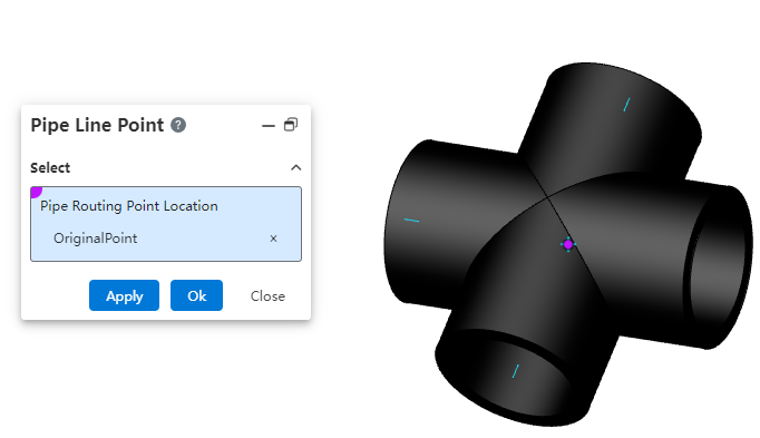
# Pipe Line Point
A route point is a point within a piping component, used to determine how the component is positioned on the 3D route sketch.
How to use:
Create a new part, and after completing the sketch, click on "Path - Connection Point."
Select the geometric elements to define the connection point's position.
Note:Please note the concepts of route points and connection points. Connection points are used to determine the connection locations of piping, while route points are used to determine how the piping component is positioned on the 3D route sketch. The following elements can be picked for route point positions: origin, sketch point, endpoint of an edge/sketch line, circular edge, or circular plane.
# Piping
# Grade Rule
Used to create and manage size and attribute rules for pipes, enabling pipe creation based on grading rules.
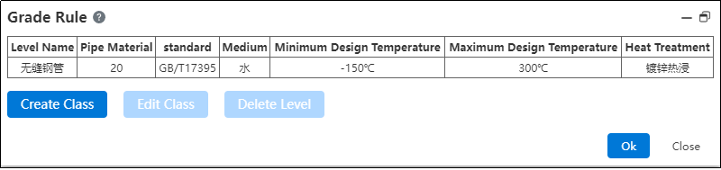
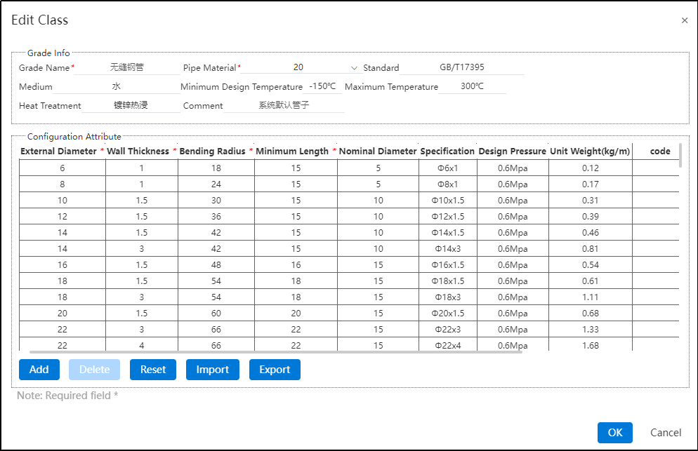
How to use:
Click on "Path - Grade Rule".
The system's default grade rule is seamless steel pipe. If you need to modify it, click "Modify Grade".
In the Modify Grade interface, you can freely edit, add, delete, import, export, or reset parameters for pipe grade information and configuration attributes. Only the system's default grade rule can be reset.
If the user needs to customize the grading rule, they can return to the grading rule interface and click "Create Grade".
After entering the create grade interface, customize according to the user's requirements. Refer to step 3) for operation guidance.
# Pipe Types
Supports creating three types of pipes: straight pipes, bent pipes, and flexible hoses. Users do not need to draw pipe profiles. By simply specifying the pipe type, parameters, and grading rules, the system can automatically generate the pipes.
# Piping Components Library
# Piping Components Library
The piping components library folder in the knowledge base can be used to store piping components.
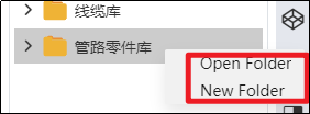
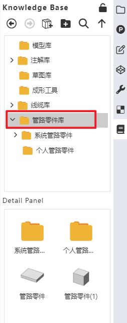
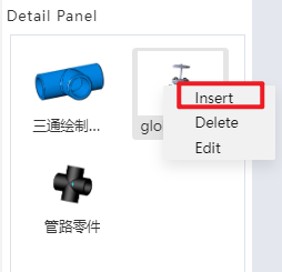
How to use:
Users can create a new folder under the "Piping Components Library" directory.
Users can right-click on a piping component, select "Insert," and then drag the component into the assembly interface.
# Add Pipe Part
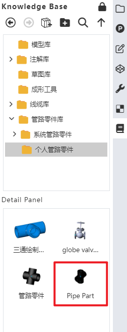
Add the part to the piping components library to support the creation of subsequent piping.
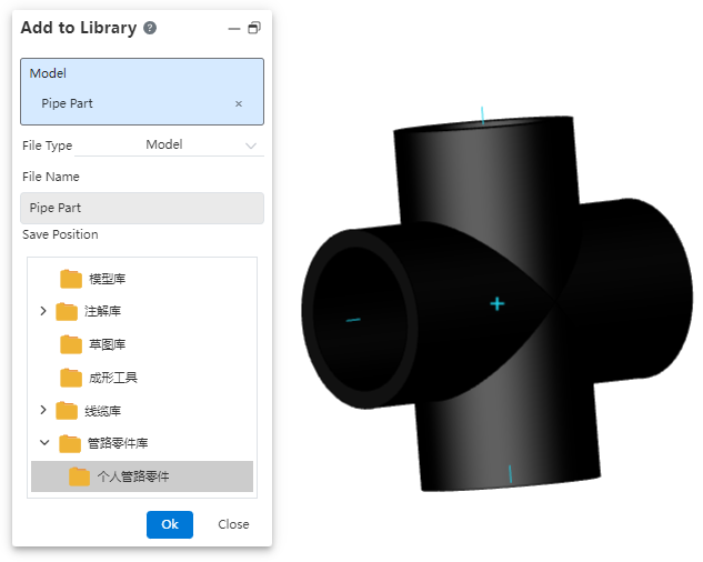
How to use:
Open "Path - Add Piping Component".
Click on the part document and set the desired storage location.
Click OK.
In the knowledge base, you can find the piping component under the storage path you just specified.
# Piping Design
# Create Pipe
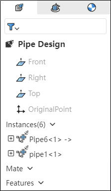
Generate a piping sub-assembly within an assembly.
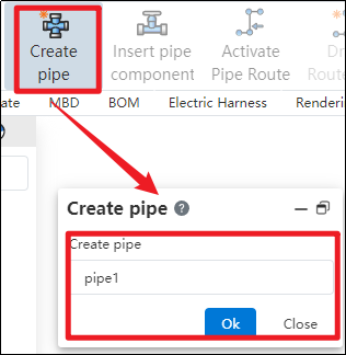
How to use:
Create a new assembly, and click "Create Piping" in the piping module.
In the pop-up dialog box, enter the name for the piping sub-assembly to be created, then click OK.
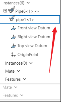
In the left-hand feature tree, if the piping instance has a blue highlighted border, it indicates that the piping is activated and ready for you to design the piping assembly according to your requirements.
# Enter/Exit Pipe
Control the entry and exit of piping sub-assemblies.
How to use:
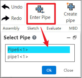
In the piping module, click "Enter Piping," select the desired piping name, and then click OK.
If the piping instance in the left feature tree has a blue highlighted border, it indicates that you have successfully entered the piping.
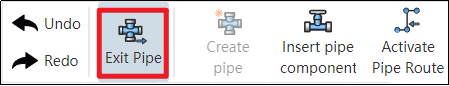
Click "Exit Piping" in the upper-left corner; if the piping instance in the left feature tree no longer has a highlight, it indicates that you have successfully exited the piping.
# Active/Exit Route
Control the activation of piping routes.
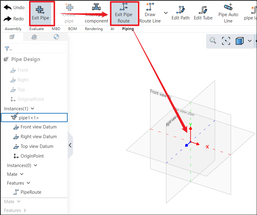
How to use:
Under the condition of entering the piping, click to activate the path
 . After activation, you can use 3D sketching to draw the piping route.
If the coordinate origin displays the three axes, it indicates that the path has been successfully activated.
Click "Exit Path" in the upper-left corner; if the three axes disappear, it indicates that the path has been successfully exited.
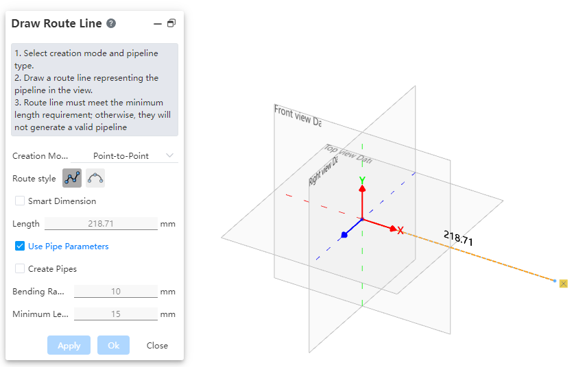
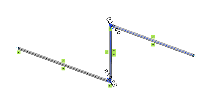
# Draw Route Line
Use this command to create a path line for the piping. The piping path defines the routing direction of the pipe, and each piping contains only one path.
How to use:
Click to create the path
 under the condition of path activation.
Users can choose the creation mode according to their drawing habits.
If the selected creation mode is "point-to-point," users can choose the line style as needed. If the selected mode is "three-axis" or "parallel to axis," the drawn path can only be a straight line.
Set the pipe parameters.
Click OK.
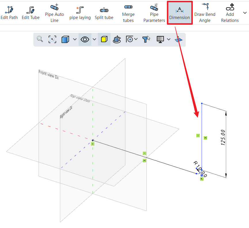
Click on the dimension constraint under the piping module to add dimensions to the created path, fully defining the 3D sketch.
Dialog Box Control Instructions:
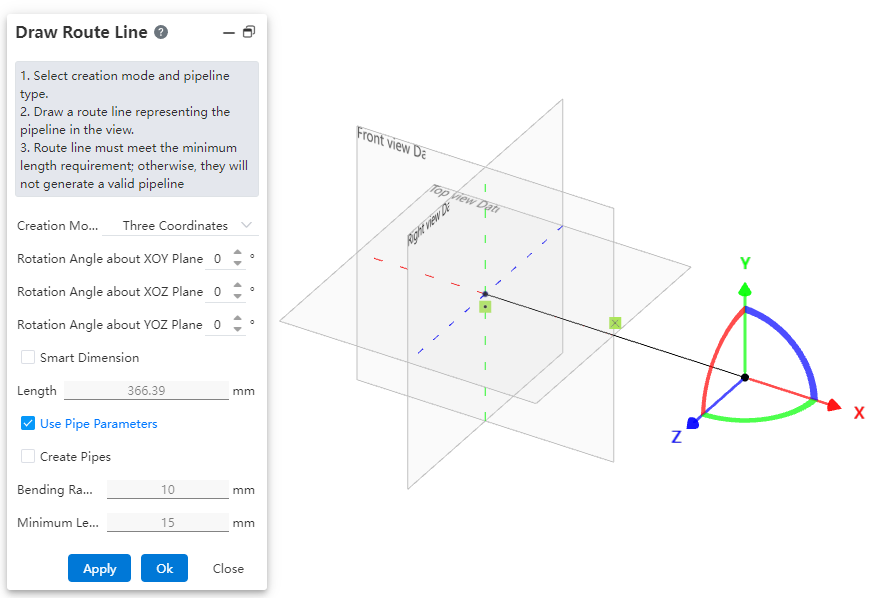
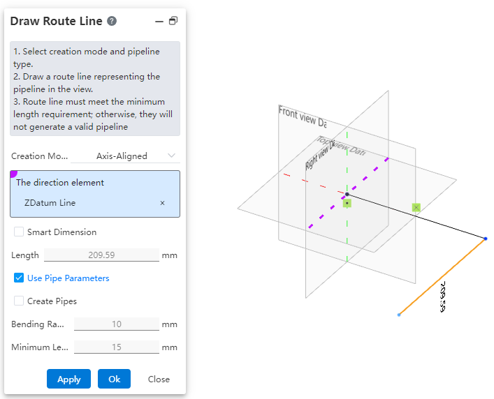
Creation Mode: The method for drawing the path.
Point-to-Point: Defines straight lines or curves based on the positions of points.
Three-Axis: Generates a path along the direction of the coordinate axes by dragging the three axes.
Parallel to Axis: Creates a path parallel to an axis by selecting a sketch line, a reference axis, or any point in space.
Create Dimension Constraints: When checked, the 3D dimensions are automatically applied to the path after entering the length.
Use Pipe Parameters: When checked, all subsequent dimension parameters after path creation are disabled and automatically use data from the "Pipe Parameters" settings. When unchecked, users can manually customize the pipe parameters.
Create Pipe: When unchecked, only the path is drawn without creating a pipe (default state). When checked, the pipe is created simultaneously with the path based on the selected options and values. Users can customize pipe parameters and choose whether to use grade-driven settings.
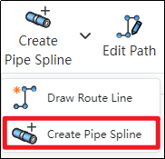
# Create Pipe Spline
Use this command to create a path line for flexible hoses, typically a spline curve.
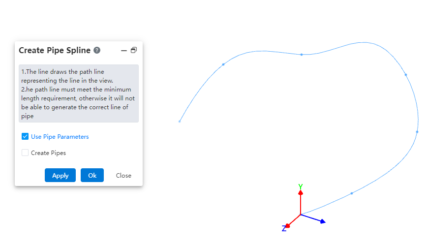
How to use:
- Under the condition of path activation, click the dropdown menu at "Draw Path" and select the "Draw Hose Path" command.
In the viewport, select different points to generate a spline curve.
Based on your requirements, choose whether to use pipe parameters and whether to create the pipe. Click OK.
Note: The operation methods for the "Pipe Parameters" and "Create Pipe" options are consistent with those in the "Draw Path" command.
# Draw Bend Angle
Manually add a bend angle between adjacent path lines.
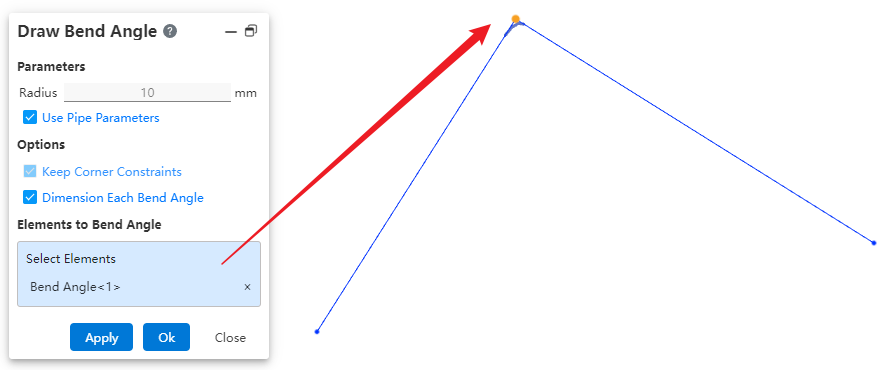
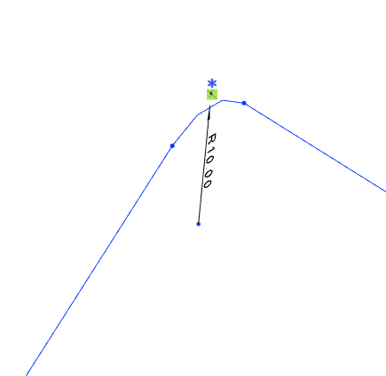
How to use:
Draw two straight lines under the condition of path activation.
Similar to the fillet command in the sketch, click on "Draw Bend Angle" to create a fillet between the two lines.
Dialog Box Control Instructions:
Use Pipe Parameters: When checked, the radius size cannot be modified. The default value is 10 mm. When unchecked, users can customize the bend angle size.
Maintain Corner Constraints: Maintains the tangent constraint between the bend angle and the two adjacent edges.
Dimension Each Bend Angle: When multiple bend locations are selected, checking this option ensures that each bend angle is dimensioned. If unchecked, only one bend angle will be dimensioned.
Elements for Bend Angle Creation: Select a vertex or a path line.
# Pipe Auto Line
After creating or activating a piping route, automatically draw a path line between the two selected connection points.
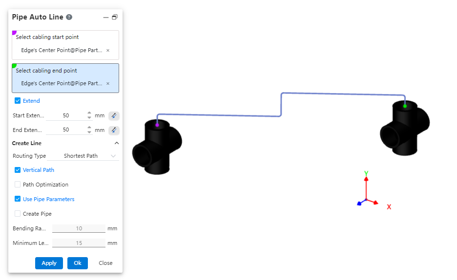
How to use:
Insert piping components.
Click the "Auto Routing" command and select the start and end points of the route.
Choose whether to extend the route outward as needed.
Select the routing method.
Choose whether to use a vertical path as required.
Set pipe parameters and decide whether to create the pipe.
Dialog Box Control Instructions:
Routing Start/End Points: You can select all connection points and the endpoints of the current piping path.
Extend Outward: When checked, the automatic routing path line will generate two additional lines at the beginning and end, extending along the direction defined by the rule.
Routing Method: Choose between the shortest path or routing along the coordinate axes.
Vertical Path: Appears when the routing method is set to shortest path. When checked, the automatically generated path lines will be perpendicular to each other.
Routing Order: Appears when the routing method is set to along coordinate axes. When checked, you can select the sequence of the three coordinate axes for routing.
Use Pipe Parameters: When checked, all subsequent dimension parameters after path creation are grayed out and use data from the "Pipe Parameters" settings. If unchecked, users can customize the pipe parameters.
Create Pipe: When unchecked, only the path is drawn without creating a pipe (default). When checked, the pipe is created simultaneously with the path based on the selected options and values. Users can customize pipe parameters and choose whether to use grade-driven settings.
# Add/Delete Relations
Add and remove constraints for route lines. Refer to the operation method for adding/removing constraints in 3D sketches.
# Edit Path
Allows modifying parameters of route lines, such as dimensions, orientation, and bend angles.
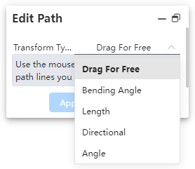
How to use:
Click the "Edit Path" command and select the method for editing the path.
Depending on the selected method, pick the geometric elements and set the parameter values.
Dialog Box Control Instructions:
Free: Allows dragging the 3D sketch of the path.
Fillet: Creates a fillet.
Length: Sets the segment length and dimension annotations.
Orientation: Moves points/path lines toward the direction of the axis.
Angle: Rotates a straight line/arc around the rotation axis by a specified angle.
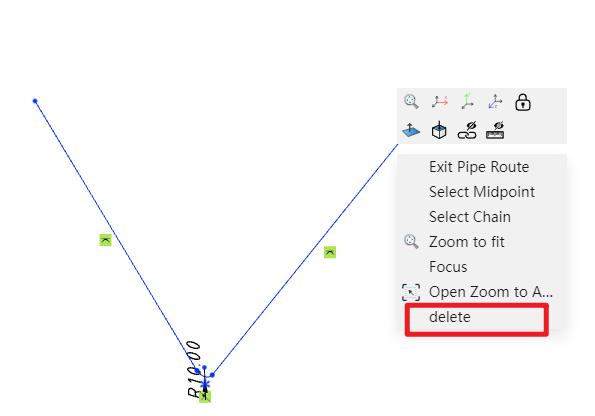
# Delete Path
Delete already drawn route lines.
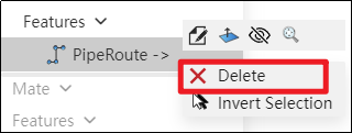
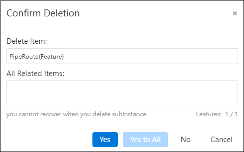
How to use:
Right-click the path feature in the feature panel and select Delete.
In the pop-up dialog box, click Yes to delete the entire path.
Note: To delete a specific segment of a path, right-click the segment and select "Delete." Alternatively, you can click on the segment and press the Delete key.
# Pipe Parameters
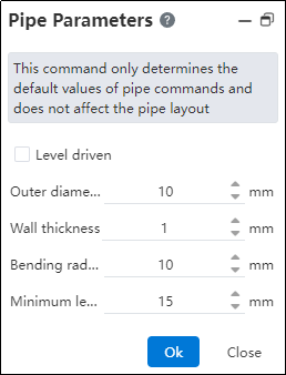
How to use:
Click on "Pipe Parameters".
Customize the default pipe values and click OK.
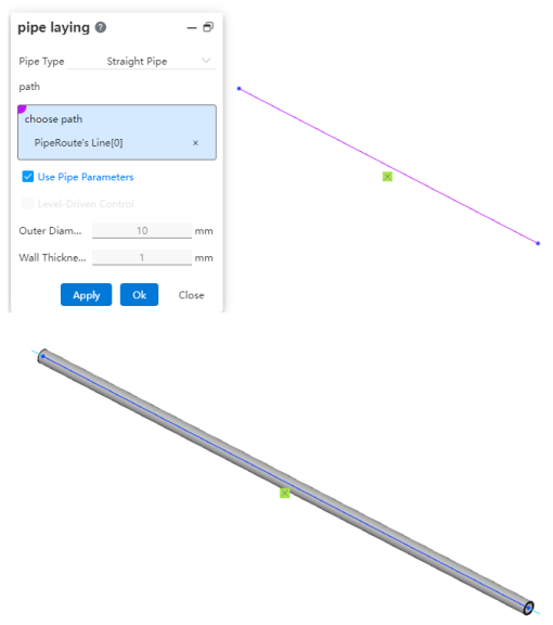
# Pipe Laying
After drawing the path, you can route pipes along it, placing the pipes onto the path.
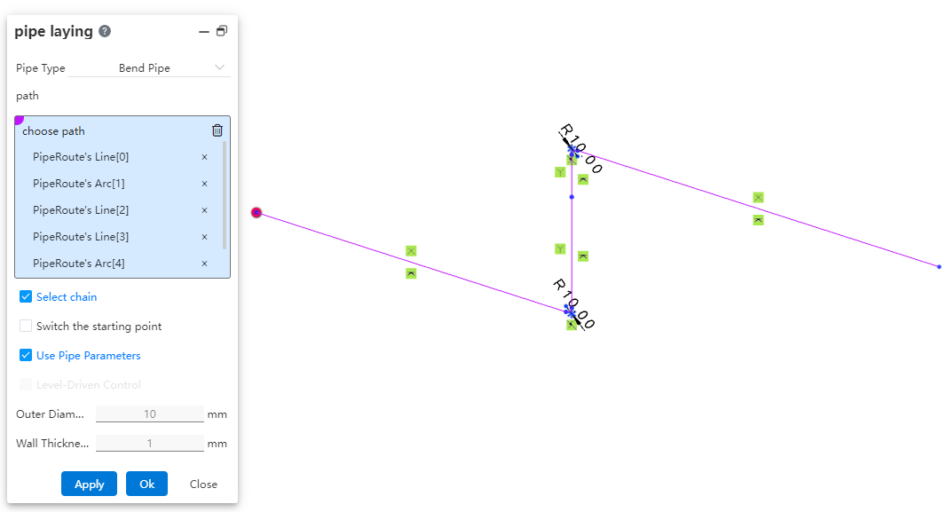
How to use:
Click "Piping." Select the type of pipe to be generated.
Select the path line. Choose whether to check "Select Chain, Switch Start Point" as needed.
Choose whether to use pipe parameters and grade-driven settings as required.
Dialog Box Control Instructions:
Select Chain: When checked, clicking on a line segment of the path will automatically pick the entire chain to which the segment belongs for routing the pipe. If the generated pipe type is a straight pipe, only individual line segments can be picked one by one, and chain selection is not supported. Chain selection is supported for bent pipes and flexible hoses.
Switch Start Point: When checked, you can change the starting position of the routed pipe. After selecting a continuous path, the start point can only be switched between the start and end points of the continuous segments. Straight pipes do not support switching the start point, while bent and flexible hoses do.
Use Pipe Parameters: When checked, all subsequent dimension parameters after path creation are grayed out and automatically use data from the "Pipe Parameters" settings. If unchecked, users can customize the pipe parameters.
Grade-Driven: When checked, you can select an existing grade rule to input data.
# Insert Pipe Component
Place piping components with piping attributes within the piping system.
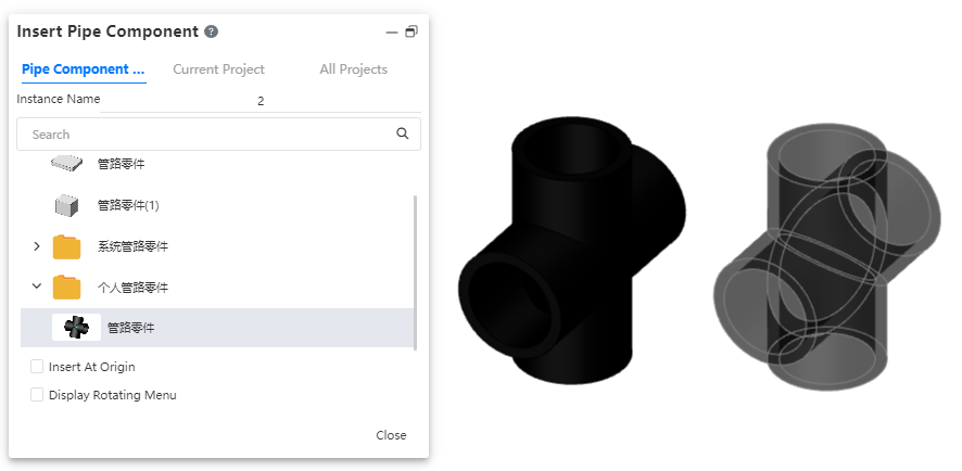
The operation method is consistent with inserting components in an assembly. The piping module has a dedicated piping components library.
# Edit Piping Component
Edit parts placed within piping, and add modeling features.
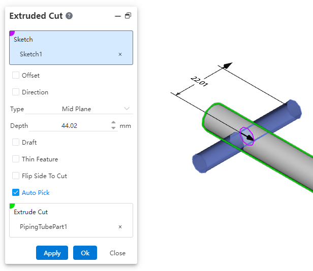
Use the "Edit Part" function under the Assembly module to add features to the pipe.
Note: The "Edit Part" function under the Assembly module cannot edit parts inserted from the knowledge base.
# Edit Piping Document
You can edit the pipe document within the piping system and continue adding modeling features.
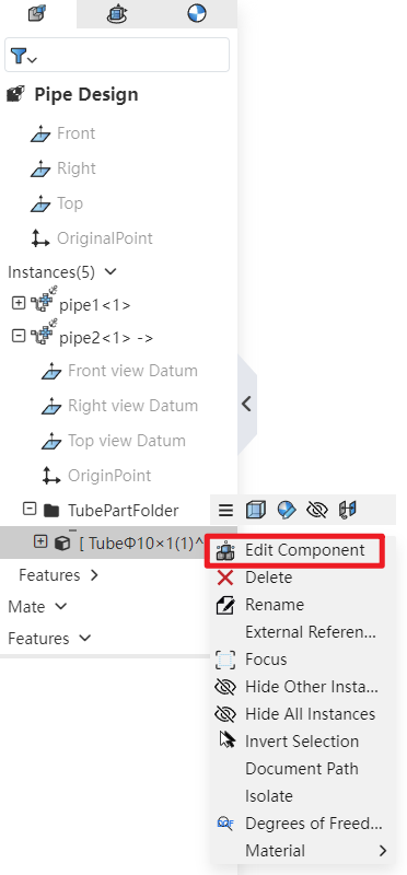
How to use: In the Feature Panel, locate the piping instance, expand it, and then find the Piping folder. After expanding the folder, right-click on the pipe and select "Edit Part" to continue adding features to the pipe.
# Edit Tube
Support editing the dimensions and specifications of already created pipes.
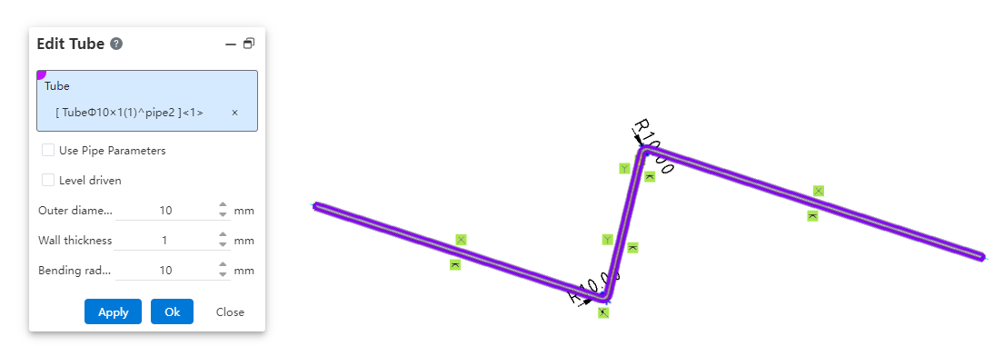
How to use:
Under the condition of path activation, click the "Edit Pipe" command.
Select the pipe to be edited and modify the pipe parameters.
Click OK; the pipe instance will be immediately updated according to the modified parameters.
# Split Tube
Break a single pipe into two connected pipes.
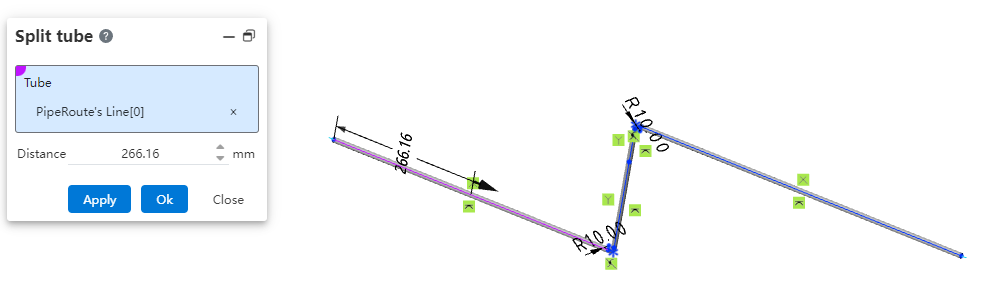

How to use:
Under the condition of path activation, click the "Break" command.
Select the path line of the pipe to be broken and set the break distance.
Click OK; the pipe will be automatically divided into two segments.
# Merge Tubes
Merge two coaxial connected pipes into a single pipe.
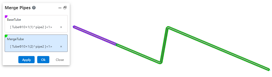
How to use:
Under the condition of path activation, click the "Merge" command.
Select the two pipe segments to be merged.
Click OK; the two pipe segments will be merged into a single pipe.
# Related Features
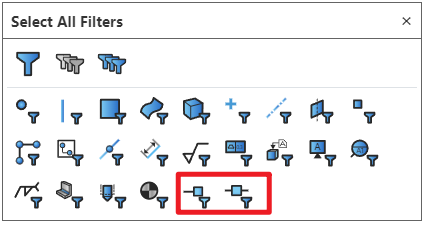
# Select Filters
Added filtering options for connection points and route points in the selection filter. After enabling the filter, only corresponding elements can be selected.
# System Setting
New piping-related options added in system settings.
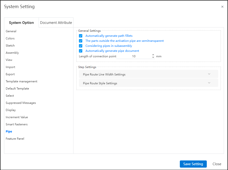
Dialog Box Control Instructions:
Automatic path fillet generation: When creating a path or performing automatic routing, automatically add a fillet between two adjacent path lines at their turning points.
Transparency of external piping components: When activating a piping route, display other components in a semi-transparent manner.
Sub-assembly piping count: Control whether piping within sub-assemblies appears in the "Enter Piping" command. If this option is unchecked, when selecting a sub-assembly containing piping in the assembly and clicking "Enter Piping," the piping name within that sub-assembly will not be displayed in the "Enter Piping" dialog.
Connection point length: Control the length of connection points displayed in the model.
Path settings: Used to control path-related parameters.
Path line width: Set the display width of the path.
Path style: Set the display style of the path. Default is line style, but circular style is also available.
# Library
# Knowledge Base Optimization
Optimize the entry and exit mechanism of model documents in the existing knowledge base.
Optimized Content:
When the piping module exists in the software, a new "Piping" folder is added to the knowledge base. Refer to "Piping Components Library" for detailed content.
After a model is stored in the knowledge base, it becomes disconnected from the original document. Subsequent edits or modifications to the original document will not affect the model in the knowledge base.
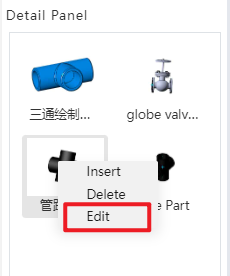
The model stored in the knowledge base can be edited. A new "Edit" option is added to the right-click menu of the knowledge base. After clicking it, a confirmation dialog box appears. Upon confirming, the model is opened in a new tab.

The newly opened library model does not have a new, import/export, or version interface. The project document name is "Knowledge Base," and the name cannot be edited. Features of the model can be edited, and changes will be synchronized to all instances using this part.
Inserting library models: When the currently open document is an assembly, models can be inserted from the knowledge base.
After a knowledge base part is checked out, if the original document in the knowledge base is deleted, the assembly document using this model will be handled the same way as a regular component document deletion.
After a knowledge base part is checked out, if the original document in the knowledge base is deleted, the assembly document using this model will be handled the same way as a regular component document deletion. That is, the part will still appear in the assembly, but right-clicking it will not display commands such as "jump to" or "edit."
When right-clicking a knowledge base model inserted into an assembly, the command menu will appear as shown in the figure below:
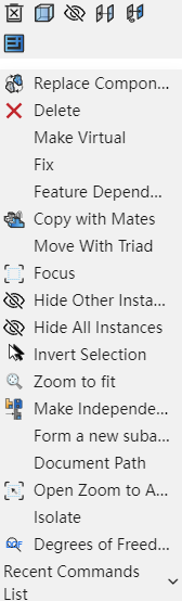
Models inserted from the knowledge base cannot perform "jump" or "edit." The right-click menu does not include options for editing components or jumping to the document. After selecting a component, the "Activate Component" command in the assembly remains grayed out.
Clicking "Document Path" in the right-click menu of a checked-out component opens the "Knowledge Base" tab and navigates to the location of the document.
Other functions in the right-click menu are consistent with those of regular components.
# Standard Part Library
The specifications of standard components such as bolts, nuts, rivets, keys, pins, retaining rings, screws, washers, bearings, and pipe fittings have been improved in the standard parts library. New components including pipe fittings, bushings, flanges, and seals have been added.