# Smart Dimension

Used to generate length, Angle, distance, radius, diameter annotations in engineering drawings.
# Generation steps
Click
 the Smart size command to bring up the Smart Size dialog box.
Click on the element you want to label in the viewport
Select a line and label its length. When the selected line is a slash, move the mouse to mark the length horizontally, vertically, or along the line direction.
Select an arc and mark its radius by default.
Select an entire circle with its diameter marked by default.
- When you label the silhouette of a cylinder by smart dimensioning, automatically add the diameter symbol before the main value of the dimension.

Select two parallel lines and label the distance.
Choose two non-parallel lines or three points and label the angles.
Select two points and label their distances. When the line of the selected points is a slash, move the mouse to mark the length horizontally, vertically, or along the line direction.
Select a line and a point and mark the shortest distance from the point to the line.
Select two elements where there is an arc/full circle and label the distance between the center of the circle and the other element.
Choose a curve and label the length of the curve.
After selecting the element you want to annotate, move your mouse to appear the annotated preview.
Move the mouse over the location where you want to place the annotation and click Generate Annotation.
Continue to select elements to annotate consecutively.
Close the Smart Size dialog box to end the labeling.
Click the already generated annotation, the Smart Size Properties dialog box will pop up, you can edit the size content.
Right-click the size boundary, size line, support hidden recovery of the hidden size witness, size line.
- Size center: You can keep the size in the middle of the size line.

# Dialog Box Control Description
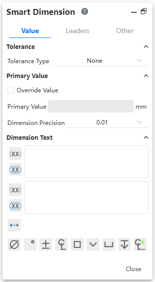
Value:
Tolerance type: Select the desired tolerance type.
Upper/lower bound variables: Input tolerance upper and lower bound variables.
Tolerance precision: Set the decimal places of the tolerance.
Cover size: After checking, you can enter a custom character to cover the real size.
Primary size value: Displays the current size value.
Annotated size text: Enter any text in it and the text appears around the size. Generally < DIM > represents the position of the main size, and the rest of the text in the viewport is consistent with its relative position and relative position in the dialog box. The text in the upside-down input box appears on the size line, and the text in the down-side input box appears below the size line.
Reference size, Review size: Click the button in front of the input box to convert the size to reference size, review size.
Size center: You can keep the size in the middle of the size line.
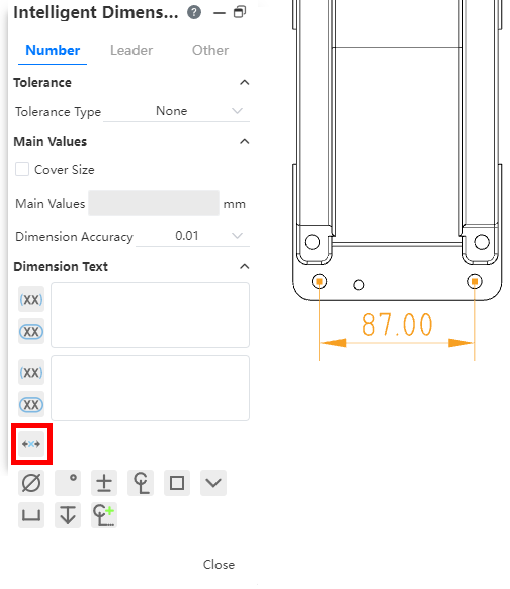
- Symbol: Position the cursor in the annotated size text input box, click the symbol button to quickly insert commonly used symbols.
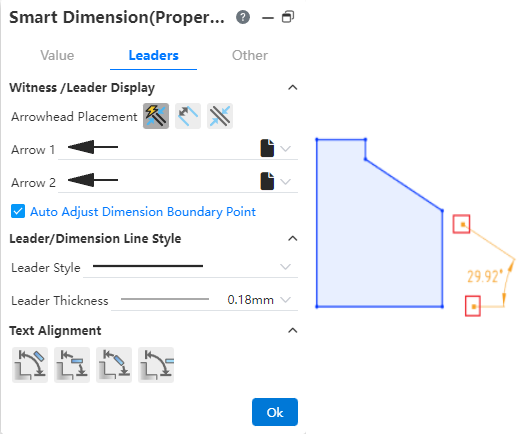
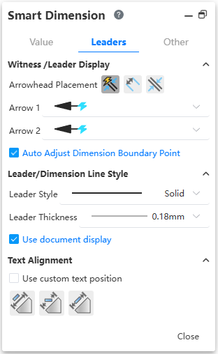
Lead: Set the arrow position, arrow type, lead/size line style of the mark. When marking a circle/arc, you can switch the "Radius, diameter, linear" marking style.
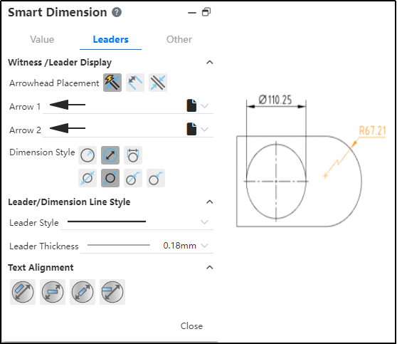
Radius style:Added the inner lead display effect setting item.

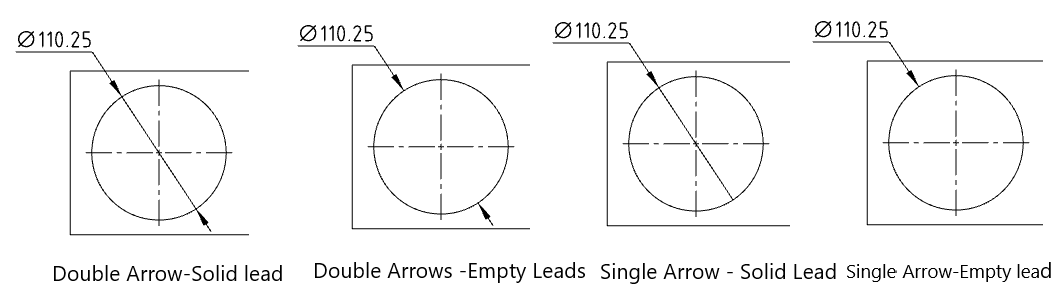
Diameter style:Added interior lead display effect and number of arrows Settings.
Linear style:Select and drag the slider rotation size shown in the image below.

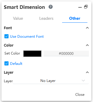
Other: Set the font and color of the label.
Note 1: When you annotate the length of the curve, the content of the dialog box will change to the "comment" style. Continue to select non-curvy elements to revert to the "Smart Size" style.
Note 2: You can only annotate elements within the same view, not between views.
# Nested Tolerances
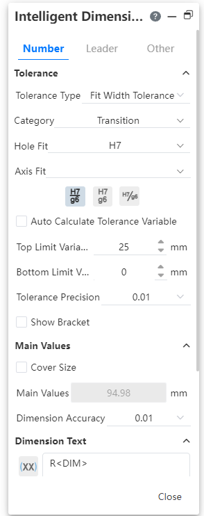
Tolerance type:Sleeve tolerance Optional "sleeve, tolerance and sleeve, sleeve (only show tolerance)" three display styles.

Cascading style:This can be used when using "Fit, Tolerance, and fit". When "hole bushing, axle bushing" is set at the same time the tolerance class code, the stacked style of the tolerance class code is controlled.
Classification:This can be used when using "sleeve fit, tolerance and sleeve fit, sleeve fit (show tolerance only)". "User Defined, Gap, Transition, Interference" may be selected.
- User definition: can be any combination of "hole sleeve close, shaft sleeve close" tolerance grade code.
- Gap, transition, interference: first set the "hole bushing (or shaft bushing)" tolerance grade code, the system automatically selects the qualified "shaft bushing (or hole bushing)" tolerance grade code can be selected.
Automatic calculation of tolerance variables:This can be used when using "tolerance and sleeve fit, sleeve fit (only show tolerance)". Used to automatically calculate tolerance values.
- "Hole bushing, axle bushing" only set the tolerance grade code of one of the items, automatically calculate the upper and lower tolerance variables according to the selected and marked size.
- When the tolerance grade code of "hole bushing and axle bushing" is set at the same time, this item is not available.
- Uncheck this, you can manually set the upper and lower tolerance variables.
Note 1:Sleeve tolerances only apply to length/distance dimensions, not Angle dimensions.
Note 2:The input box of "hole fitting, shaft fitting" can input text to quickly retrieve the required tolerance level code, or you can directly input text, delete the text to clear the options.
# Maximum/Minimum Dimension
Optional Maximum/Minimum Dimension when marking circle/arc.
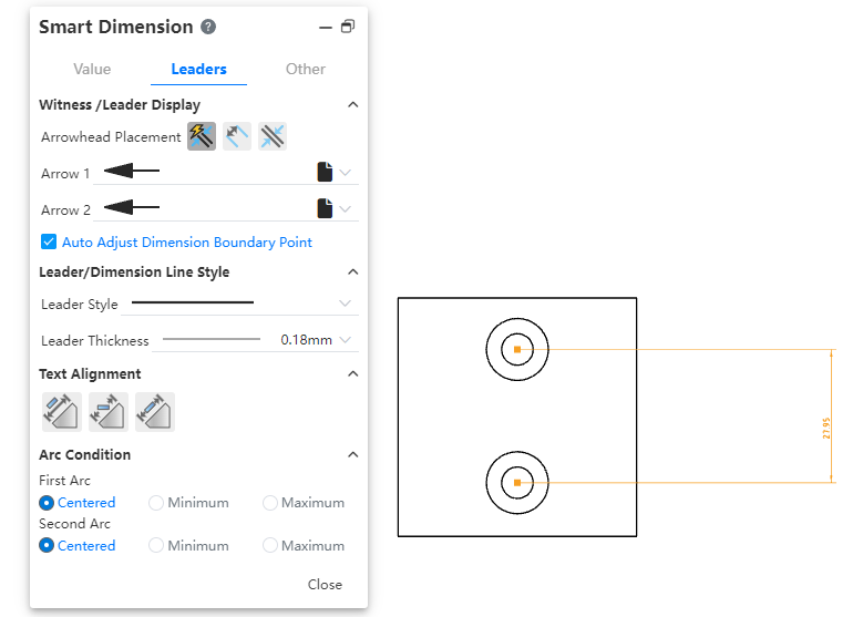
How to use:
1) Click the Smart Size command.
2) Mark the distance between the circle or arc and the other elements.
3) The dialog box switches to the "Lead" Tab and modifies the arc condition.
# Dimension Boundary Lines

Default style: Size boundary parameters can be set in System Settings - Document Properties - Dimensions.
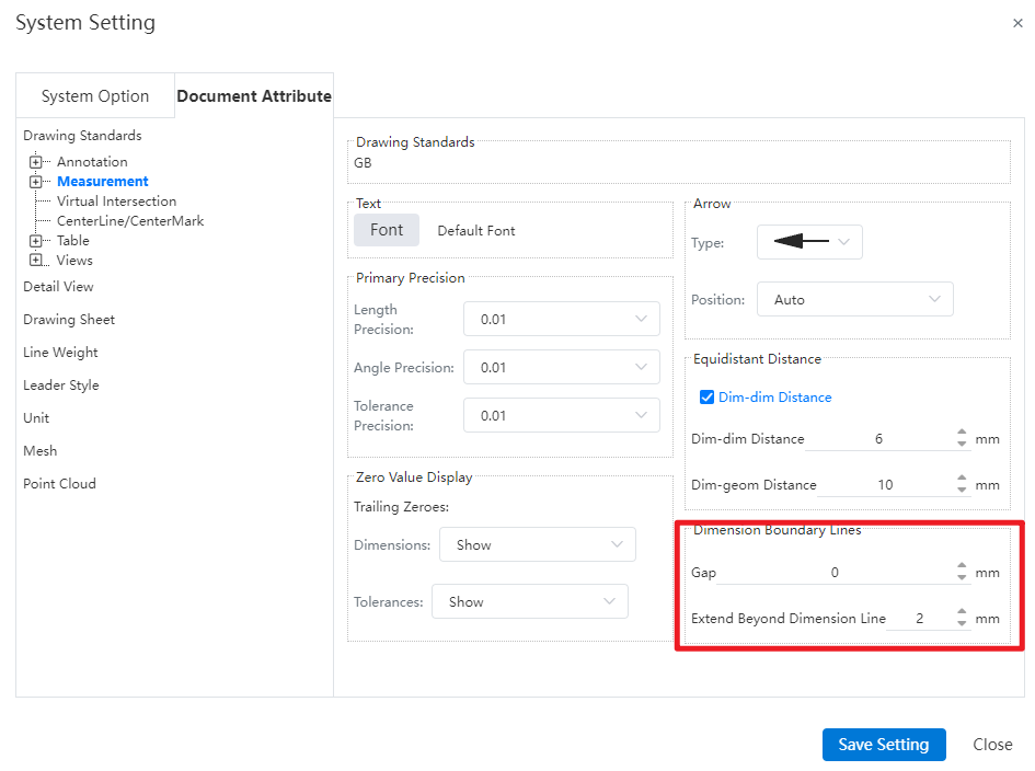
Gap: The gap between the size boundary line and the annotated element.
Beyond the size line length: The length of the size boundary line beyond the size line.
Manual adjustment: Select the Angle or length size, uncheck "Automatically adjust the size boundary end point" in the lead Tab of the size property dialog box, the square control mark is displayed at the end of the size boundary line, you can manually drag the control mark to adjust the boundary line. Check it again to restore the automatic adjustment of the boundary line.