# Piping
# Piping component design
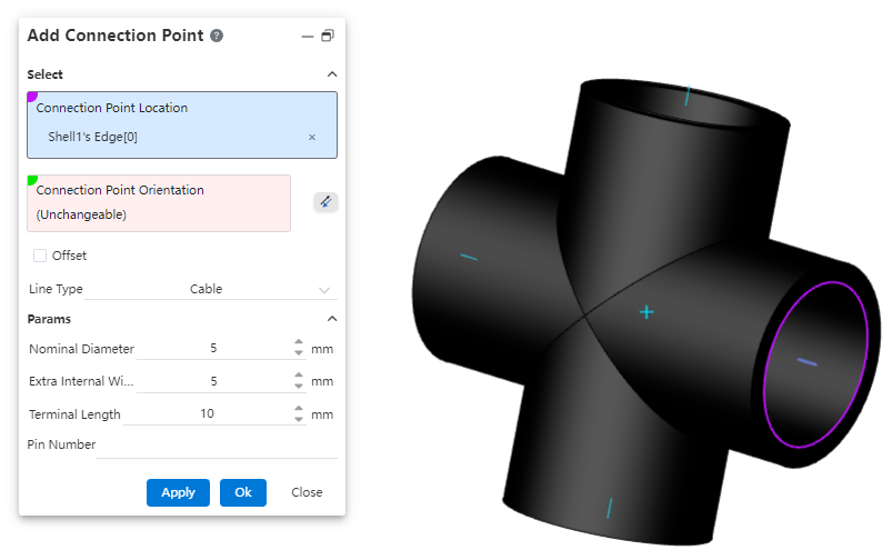
# Add Connection Point
A connection point is a feature displayed as a directional axis, used to control the start/end point of a pipe and also to manage connections between piping components.
How to use:
Create a new part, complete the sketch, then click on "Path - Connection Point."
Select the geometric elements to define the connection point's position.
If the selected geometric element is a circular edge or a plane, the system defaults the connection point direction to be perpendicular to the plane. You can click the reverse icon to change the orientation. If the selected element is a sketch line/point or a model edge, the connection point direction must be manually defined by selecting a geometric element.
Determine whether the connection point needs to be offset based on your requirements.
Select the piping type, and determine whether to enable the grade rule based on your requirements.
Set the relevant parameters.
Dialog Box Control Instructions:
Connection Point Position: Only a single geometric element can be selected. Supported elements for selection: origin, sketch point, endpoint of an edge/sketch line, circular edge, or circular plane as the connection point position.
Connection Point Direction: If the selected connection point position does not require a specified direction, the system will automatically fill in the direction. If a direction needs to be defined, the user must manually pick a geometric element to determine the direction.
Offset: Controls whether the connection point starts from an offset along the connection point direction from the initial position. By default, this is unchecked.
Category: Options include "Piping," "Cable," and "Wire." Parameters differ between the Piping and Cable categories.
Grade Rule: Appears only when the category is set to "Piping." Used to record the piping attributes of the part. The system default grade rule is seamless steel pipe. Users can customize the grade rule in the "Path - Grade Rule" section.
Outer Diameter / Wall Thickness / Flow Direction: Basic pipe attributes, required fields.
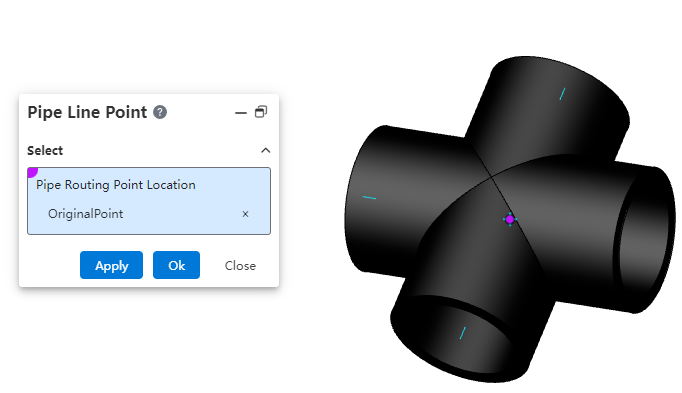
# Pipe Line Point
A route point is a point within a piping component, used to determine how the component is positioned on the 3D route sketch.
How to use:
Create a new part, and after completing the sketch, click on "Path - Connection Point."
Select the geometric elements to define the connection point's position.
Note:Please note the concepts of route points and connection points. Connection points are used to determine the connection locations of piping, while route points are used to determine how the piping component is positioned on the 3D route sketch. The following elements can be picked for route point positions: origin, sketch point, endpoint of an edge/sketch line, circular edge, or circular plane.
# Piping
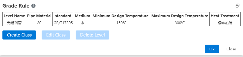
# Grade Rule
Used to create and manage size and attribute rules for pipes, enabling pipe creation based on grading rules.
How to use:
Click on "Path - Grade Rule".
The system's default grade rule is seamless steel pipe. If you need to modify it, click "Modify Grade".
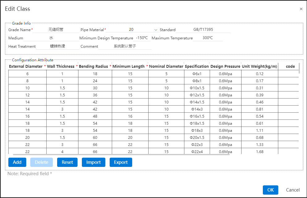
In the Modify Grade interface, you can freely edit, add, delete, import, export, or reset parameters for pipe grade information and configuration attributes. Only the system's default grade rule can be reset.
If the user needs to customize the grading rule, they can return to the grading rule interface and click "Create Grade".
After entering the create grade interface, customize according to the user's requirements. Refer to step 3) for operation guidance.
# Pipe Types
Supports creating three types of pipes: straight pipes, bent pipes, and flexible hoses. Users do not need to draw pipe profiles. By simply specifying the pipe type, parameters, and grading rules, the system can automatically generate the pipes.
# Piping Components Library
# Piping Components Library
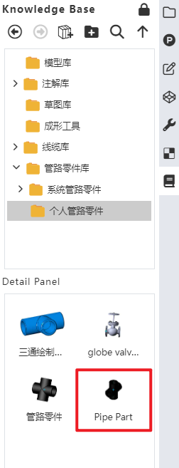
The piping components library folder in the knowledge base can be used to store piping components.
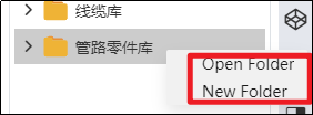
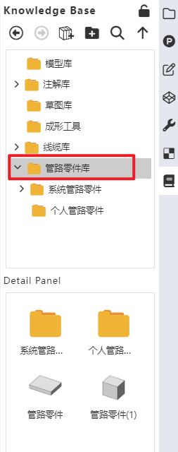
How to use:
Users can create a new folder under the "Piping Components Library" directory.
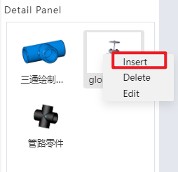
Users can right-click on a piping component, select "Insert," and then drag the component into the assembly interface.
# Add Pipe Part
Add the part to the piping components library to support the creation of subsequent piping.
How to use:
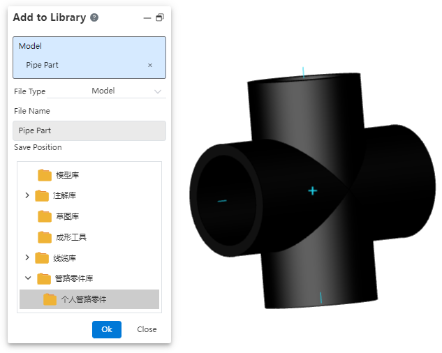
Open "Path - Add Piping Component".
Click on the part document and set the desired storage location.
Click OK.
In the knowledge base, you can find the piping component under the storage path you just specified.
# Piping Design
# Create Pipe
Generate a piping sub-assembly within an assembly.
How to use:
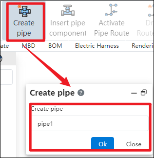
Create a new assembly, and click "Create Piping" in the piping module.
In the pop-up dialog box, enter the name for the piping sub-assembly to be created, then click OK.
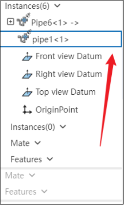
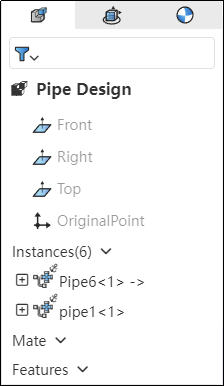
In the left-hand feature tree, if the piping instance has a blue highlighted border, it indicates that the piping is activated and ready for you to design the piping assembly according to your requirements.
# Enter/Exit Pipe
Control the entry and exit of piping sub-assemblies.
How to use:
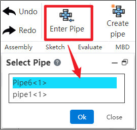
In the piping module, click "Enter Piping," select the desired piping name, and then click OK.
If the piping instance in the left feature tree has a blue highlighted border, it indicates that you have successfully entered the piping.
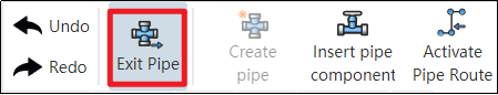
Click "Exit Piping" in the upper-left corner; if the piping instance in the left feature tree no longer has a highlight, it indicates that you have successfully exited the piping.
# Active/Exit Route
Control the activation of piping routes.
How to use:
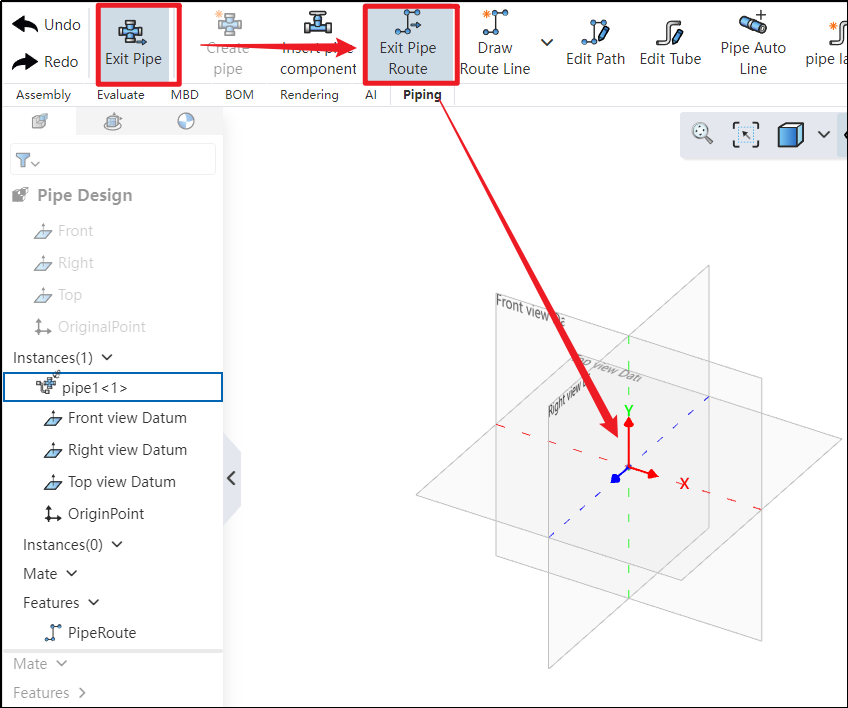
Under the condition of entering the piping, click to activate the path
 . After activation, you can use 3D sketching to draw the piping route.
If the coordinate origin displays the three axes, it indicates that the path has been successfully activated.
Click "Exit Path" in the upper-left corner; if the three axes disappear, it indicates that the path has been successfully exited.
# Draw Route Line
Use this command to create a path line for the piping. The piping path defines the routing direction of the pipe, and each piping contains only one path.
How to use:
Click to create the path
 under the condition of path activation.
Users can choose the creation mode according to their drawing habits.
If the selected creation mode is "point-to-point," users can choose the line style as needed. If the selected mode is "three-axis" or "parallel to axis," the drawn path can only be a straight line.
Set the pipe parameters.
Click OK.
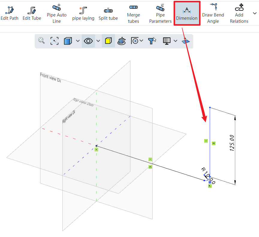
Click on the dimension constraint under the piping module to add dimensions to the created path, fully defining the 3D sketch.
Dialog Box Control Instructions:
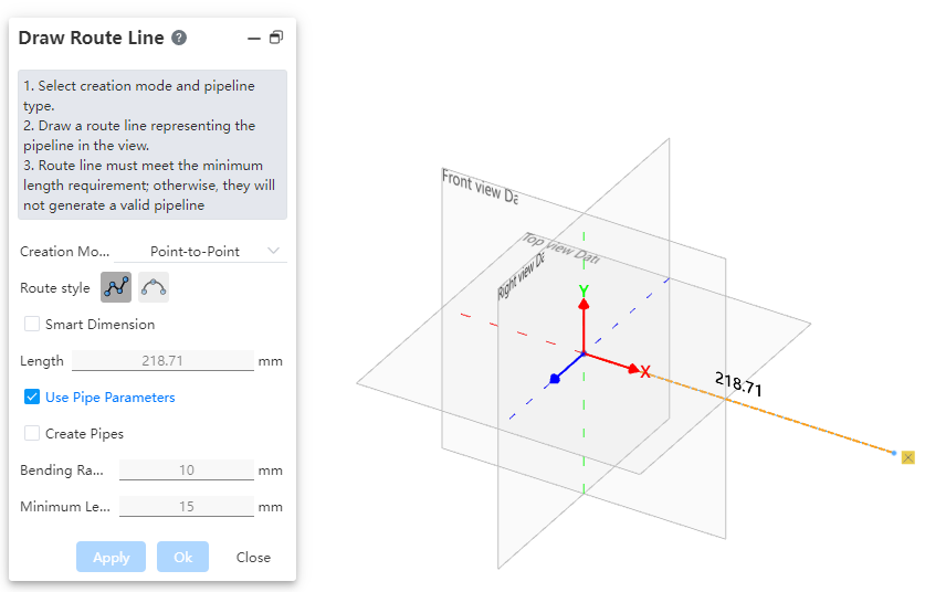
Creation Mode: The method for drawing the path.
Point-to-Point: Defines straight lines or curves based on the positions of points.
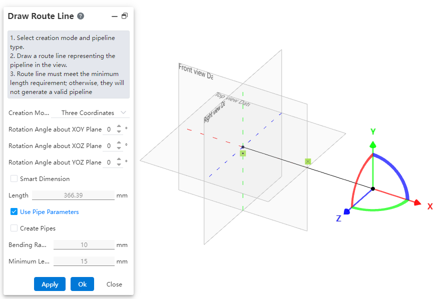
Three-Axis: Generates a path along the direction of the coordinate axes by dragging the three axes.
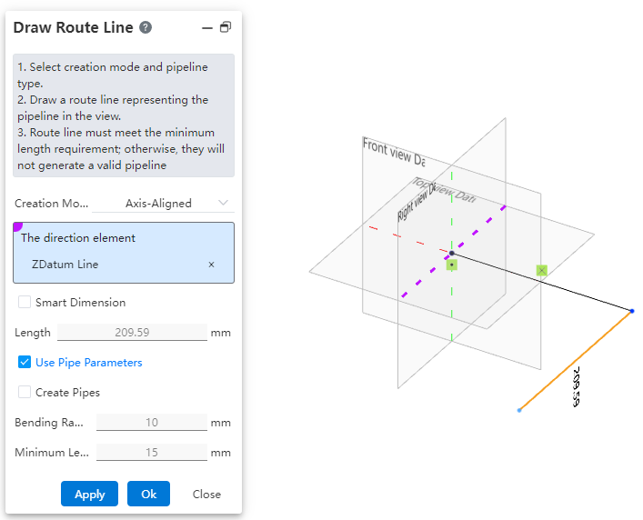
Parallel to Axis: Creates a path parallel to an axis by selecting a sketch line, a reference axis, or any point in space.
Create Dimension Constraints: When checked, the 3D dimensions are automatically applied to the path after entering the length.
Use Pipe Parameters: When checked, all subsequent dimension parameters after path creation are disabled and automatically use data from the "Pipe Parameters" settings. When unchecked, users can manually customize the pipe parameters.
Create Pipe: When unchecked, only the path is drawn without creating a pipe (default state). When checked, the pipe is created simultaneously with the path based on the selected options and values. Users can customize pipe parameters and choose whether to use grade-driven settings.
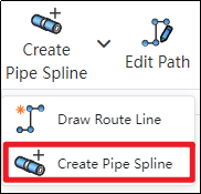
# Create Pipe Spline
Use this command to create a path line for flexible hoses, typically a spline curve.
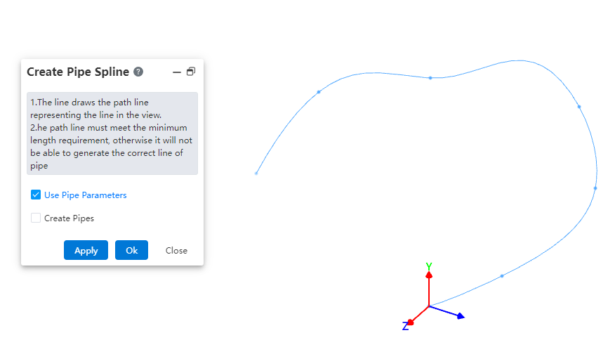
How to use:
- Under the condition of path activation, click the dropdown menu at "Draw Path" and select the "Draw Hose Path" command.
In the viewport, select different points to generate a spline curve.
Based on your requirements, choose whether to use pipe parameters and whether to create the pipe. Click OK.
Note: The operation methods for the "Pipe Parameters" and "Create Pipe" options are consistent with those in the "Draw Path" command.
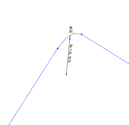
# Draw Bend Angle
Manually add a bend angle between adjacent path lines.
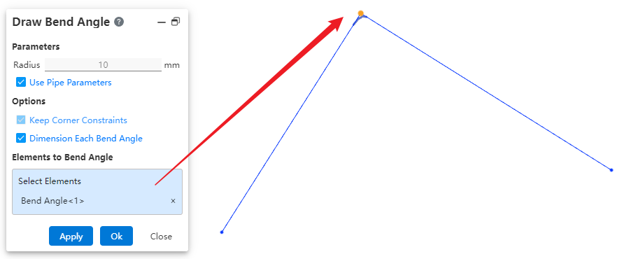
How to use:
Draw two straight lines under the condition of path activation.
Similar to the fillet command in the sketch, click on "Draw Bend Angle" to create a fillet between the two lines.
Dialog Box Control Instructions:
Use Pipe Parameters: When checked, the radius size cannot be modified. The default value is 10 mm. When unchecked, users can customize the bend angle size.
Maintain Corner Constraints: Maintains the tangent constraint between the bend angle and the two adjacent edges.
Dimension Each Bend Angle: When multiple bend locations are selected, checking this option ensures that each bend angle is dimensioned. If unchecked, only one bend angle will be dimensioned.
Elements for Bend Angle Creation: Select a vertex or a path line.
# Pipe Auto Line
After creating or activating a piping route, automatically draw a path line between the two selected connection points.
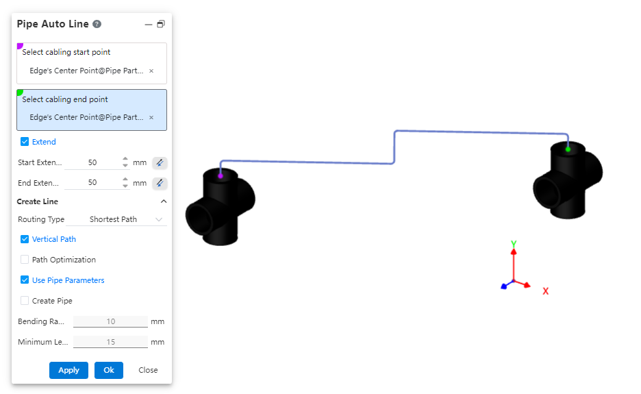
How to use:
Insert piping components.
Click the "Auto Routing" command and select the start and end points of the route.
Choose whether to extend the route outward as needed.
Select the routing method.
Choose whether to use a vertical path as required.
Set pipe parameters and decide whether to create the pipe.
Dialog Box Control Instructions:
Routing Start/End Points: You can select all connection points and the endpoints of the current piping path.
Extend Outward: When checked, the automatic routing path line will generate two additional lines at the beginning and end, extending along the direction defined by the rule.
Routing Method: Choose between the shortest path or routing along the coordinate axes.
Vertical Path: Appears when the routing method is set to shortest path. When checked, the automatically generated path lines will be perpendicular to each other.
Routing Order: Appears when the routing method is set to along coordinate axes. When checked, you can select the sequence of the three coordinate axes for routing.
Use Pipe Parameters: When checked, all subsequent dimension parameters after path creation are grayed out and use data from the "Pipe Parameters" settings. If unchecked, users can customize the pipe parameters.
Create Pipe: When unchecked, only the path is drawn without creating a pipe (default). When checked, the pipe is created simultaneously with the path based on the selected options and values. Users can customize pipe parameters and choose whether to use grade-driven settings.
# Add/Delete Relations
Add and remove constraints for route lines. Refer to the operation method for adding/removing constraints in 3D sketches.
# Edit Path
Allows modifying parameters of route lines, such as dimensions, orientation, and bend angles.
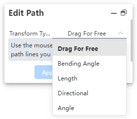
How to use:
Click the "Edit Path" command and select the method for editing the path.
Depending on the selected method, pick the geometric elements and set the parameter values.
Dialog Box Control Instructions:
Free: Allows dragging the 3D sketch of the path.
Fillet: Creates a fillet.
Length: Sets the segment length and dimension annotations.
Orientation: Moves points/path lines toward the direction of the axis.
Angle: Rotates a straight line/arc around the rotation axis by a specified angle.
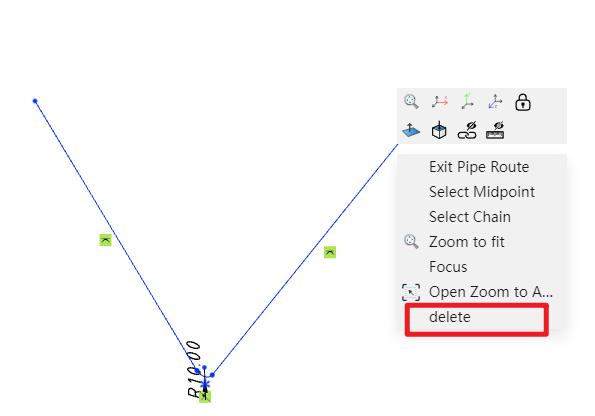
# Delete Path
Delete already drawn route lines.
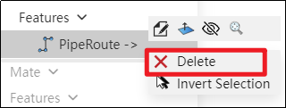
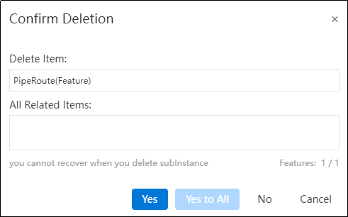
How to use:
Right-click the path feature in the feature panel and select Delete.
In the pop-up dialog box, click Yes to delete the entire path.
Note: To delete a specific segment of a path, right-click the segment and select "Delete." Alternatively, you can click on the segment and press the Delete key.
# Pipe Parameters
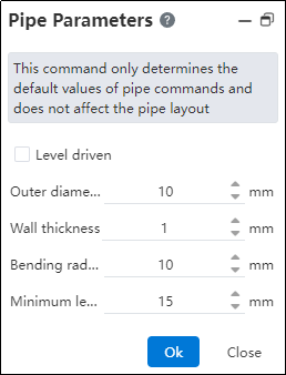
How to use:
Click on "Pipe Parameters".
Customize the default pipe values and click OK.
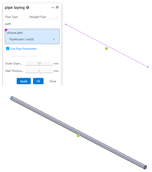
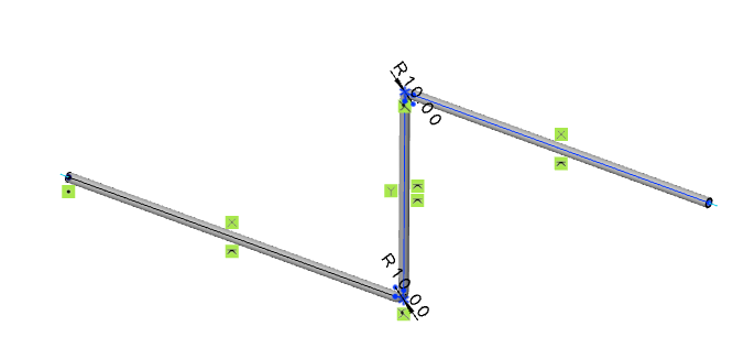
# Pipe Laying
After drawing the path, you can route pipes along it, placing the pipes onto the path.
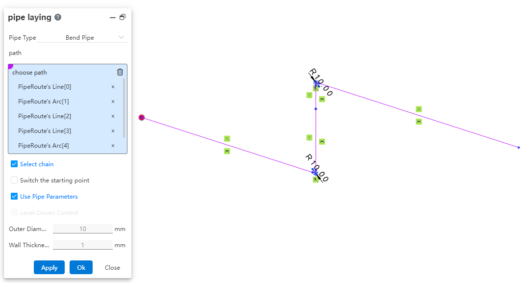
How to use:
Click "Piping." Select the type of pipe to be generated.
Select the path line. Choose whether to check "Select Chain, Switch Start Point" as needed.
Choose whether to use pipe parameters and grade-driven settings as required.
Dialog Box Control Instructions:
Select Chain: When checked, clicking on a line segment of the path will automatically pick the entire chain to which the segment belongs for routing the pipe. If the generated pipe type is a straight pipe, only individual line segments can be picked one by one, and chain selection is not supported. Chain selection is supported for bent pipes and flexible hoses.
Switch Start Point: When checked, you can change the starting position of the routed pipe. After selecting a continuous path, the start point can only be switched between the start and end points of the continuous segments. Straight pipes do not support switching the start point, while bent and flexible hoses do.
Use Pipe Parameters: When checked, all subsequent dimension parameters after path creation are grayed out and automatically use data from the "Pipe Parameters" settings. If unchecked, users can customize the pipe parameters.
Grade-Driven: When checked, you can select an existing grade rule to input data.
# Insert Pipe Component
Place piping components with piping attributes within the piping system.
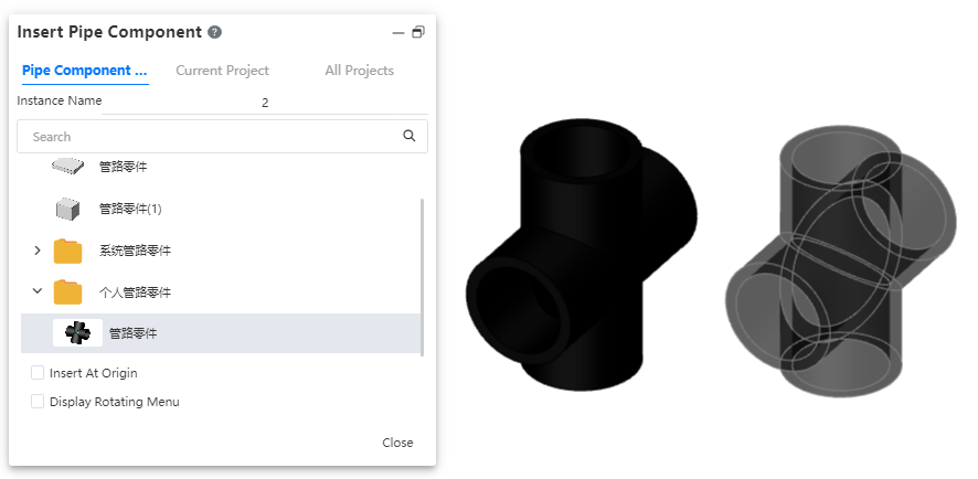
The operation method is consistent with inserting components in an assembly. The piping module has a dedicated piping components library.
# Edit Piping Component
Edit parts placed within piping, and add modeling features.
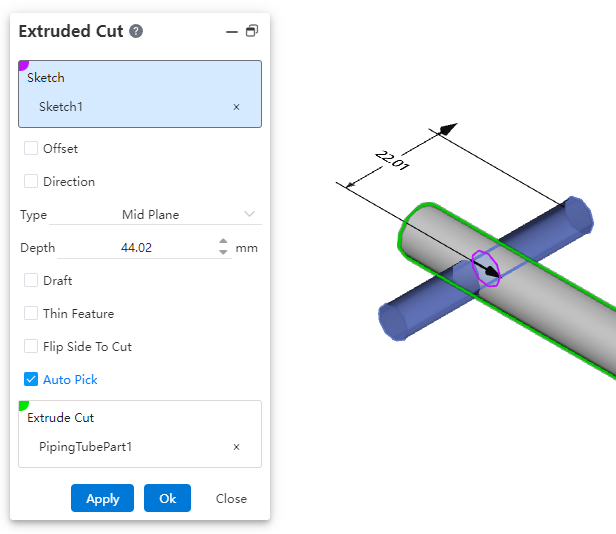
Use the "Edit Part" function under the Assembly module to add features to the pipe.
Note: The "Edit Part" function under the Assembly module cannot edit parts inserted from the knowledge base.
# Edit Piping Document
You can edit the pipe document within the piping system and continue adding modeling features.
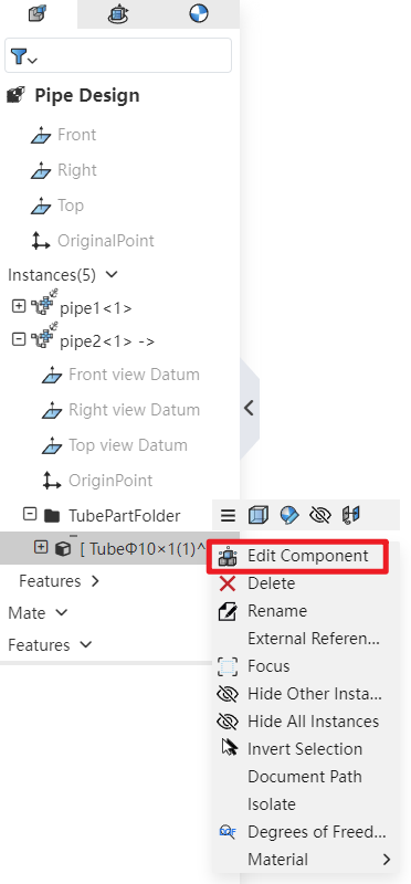
How to use: In the Feature Panel, locate the piping instance, expand it, and then find the Piping folder. After expanding the folder, right-click on the pipe and select "Edit Part" to continue adding features to the pipe.
# Edit Tube
Support editing the dimensions and specifications of already created pipes.
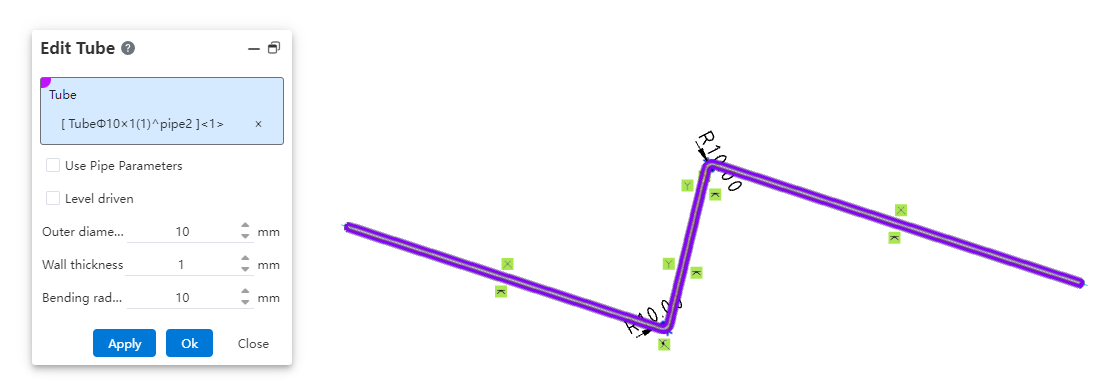
How to use:
Under the condition of path activation, click the "Edit Pipe" command.
Select the pipe to be edited and modify the pipe parameters.
Click OK; the pipe instance will be immediately updated according to the modified parameters.
# Split Tube
Break a single pipe into two connected pipes.
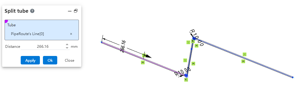

How to use:
Under the condition of path activation, click the "Break" command.
Select the path line of the pipe to be broken and set the break distance.
Click OK; the pipe will be automatically divided into two segments.
# Merge Tubes
Merge two coaxial connected pipes into a single pipe.
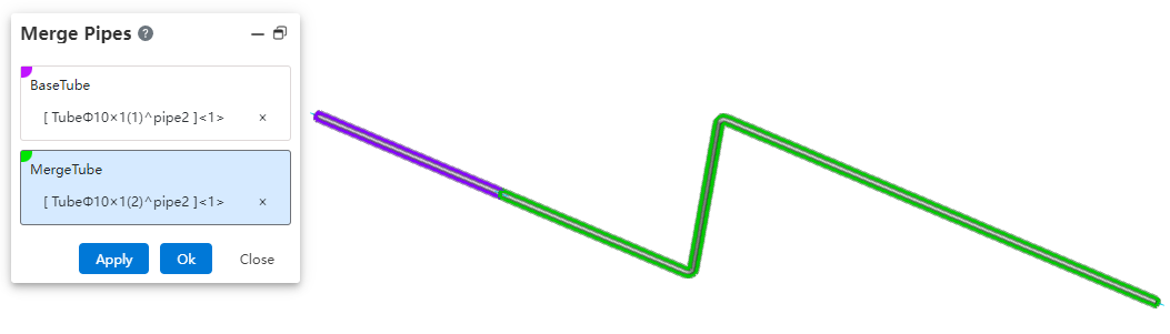
How to use:
Under the condition of path activation, click the "Merge" command.
Select the two pipe segments to be merged.
Click OK; the two pipe segments will be merged into a single pipe.
# Related Features
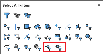
# Select Filters
Added filtering options for connection points and route points in the selection filter. After enabling the filter, only corresponding elements can be selected.
# System Setting
New piping-related options added in system settings.
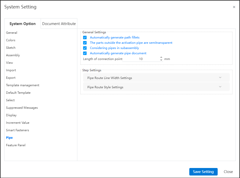
Dialog Box Control Instructions:
Automatic path fillet generation: When creating a path or performing automatic routing, automatically add a fillet between two adjacent path lines at their turning points.
Transparency of external piping components: When activating a piping route, display other components in a semi-transparent manner.
Sub-assembly piping count: Control whether piping within sub-assemblies appears in the "Enter Piping" command. If this option is unchecked, when selecting a sub-assembly containing piping in the assembly and clicking "Enter Piping," the piping name within that sub-assembly will not be displayed in the "Enter Piping" dialog.
Connection point length: Control the length of connection points displayed in the model.
Path settings: Used to control path-related parameters.
Path line width: Set the display width of the path.
Path style: Set the display style of the path. Default is line style, but circular style is also available.