
# Welcome to CrownCAD 2026 R2
CrownCAD 2026 R2 incorporates extensive user feedback to fully meet your design requirements. In terms of usability, we are committed to enhancing user experience; in functionality, we continuously add essential commands that help you quickly complete product design and development tasks.
Main Enhancements:
| Sketch | Support for directly importing local DWG files into sketches. |
| Supports copying sketches to a specified plane. | |
| Supports concentric constraint between 3D sketch lines and circular elements. | |
| Features | Loft boss/base supports end constraints, with three new constraint types added: direction vector, perpendicular to sketch, and tangent to face. |
| Sheet Metal | Added the lofted bend command, which can be used to create square-ended ventilation openings and other sheet metal components. |
| Drawing | Support the creation of centerlines through arc slots and sketch elements; enhance linear and circular centerline annotation scenarios, aligning with slot and sketch element linear and circular annotations. |
| Supports adapting hole annotation creation styles through multiline text position for different drawing standards. | |
| Piping | Split the Interface Points function into Piping Interfaces and Electrical Interfaces, and update the display styles of Piping Interfaces in the viewport. |
| Add the Path Axis feature, which can be used to set intermediate positions of path lines in pipelines. | |
| When creating a pipeline, it supports setting pipeline parameters. | |
| When drawing a path, add a checkbox option for "End point path vertical". | |
| Inserting piping component support allows users to insert instances that match the characteristics of piping components from the current project or other projects as fittings. | |
| Add automatic bend angle, support picking path chain to automatically create bend angle. | |
| Automatic routing supports picking up the path axis to set the via points of the path line. | |
| Add flexible hose automatic routing, supporting automatic layout of flexible hose path lines based on starting points and path axes. | |
| BOM | In the BOM tool - materials breakdown form, it is possible to set whether to consolidate pipes. |
# Sketch
# Insert DWG
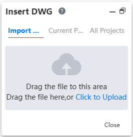
Supports directly importing local DWG files into the sketch. After clicking the import button, the document will be imported into the project and inserted into the current sketch.
# Copy Sketch
Supports selecting a sketch and then clicking Ctrl+C to copy the sketch. Clicking Ctrl+V will copy it to the front view reference plane. If a plane is selected after clicking Ctrl+V, it can be pasted to the corresponding plane.
# Co-axial Constraint
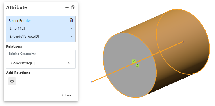
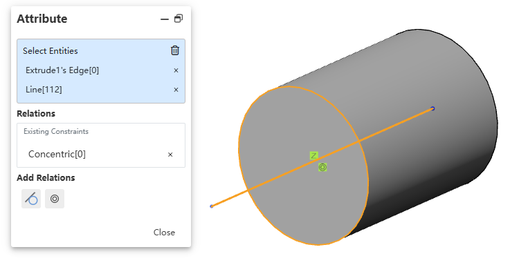
Supports selecting straight lines and/or cylindrical surfaces or arc curves inside a 3D sketch to add "Co-axial Constraint", making the selected straight line and the axis of the cylindrical surface or arc curve aligned (same axis), ensuring that the two maintain an accurate coaxial relationship in space.
# Features
# Lofted Boss/Base
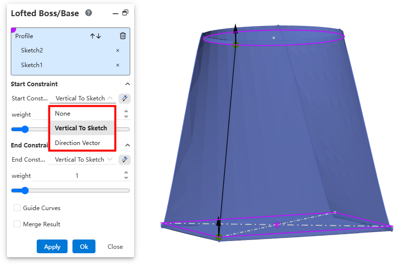
Loft boss/base supports end constraints, with three new constraint types added: direction vector, perpendicular to sketch, and tangent to face.
# Sheet Metal
# Lofted Bend
Added the Lofted Bend command, which can be used to create sheet metal components such as the round-to-square ventilation openings.
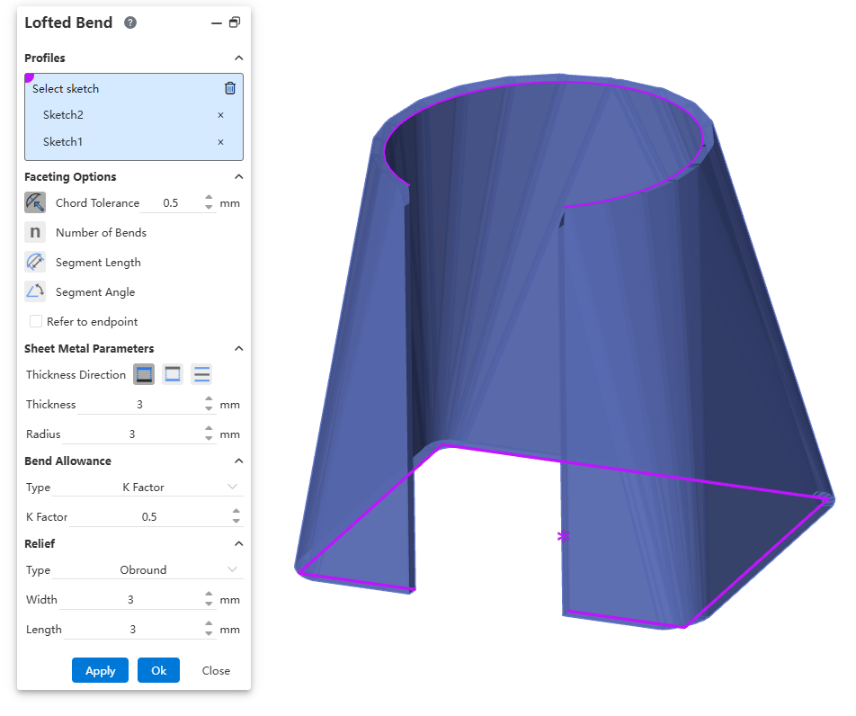
How to use:
Open the Developed Bend command.
Pick two sketches as the profiles for the develop.
Set the parameters and options.
Click OK to complete the feature creation.
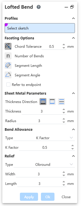
Dialog Box Controls Explanation:
Select Sketches: Pick two sketch profiles.
Developed Bend Options: Controls the effect of the developed bend, influencing the number of bends.
Reference End: Controls the effect at the corners of the profile edges.
Thickness Direction: Chooses the "thicken" direction relative to the sketch profiles.
Thickness: Sets the thickness of the sheet metal.
Radius: Sets the radius of the bend in the sheet metal.
Developed Bend Parameters, Release Slot: Similar to Base Flange.
Explanations:
Sketches must be single, continuous, non-crossing open loop contour.
Sketches must be located on parallel reference planes or flat surfaces.
The opening direction of the sketches must be clear and consistent.
Linear edges of the two sketches should be parallel, and the number of line segments should be as equal as possible.
Avoid sharp transitions; add fillet arcs at complex changes.
# Drawing
# Center Mark
Enhancement of the Centerline Command Functionality: Expanding the types of objects that can be created using centerlines, now supporting the creation of centerlines via arc slots and sketch elements. Enriching the scenarios for linear and circular centerline annotations, including support for linear and circular annotations of slots and sketch elements.
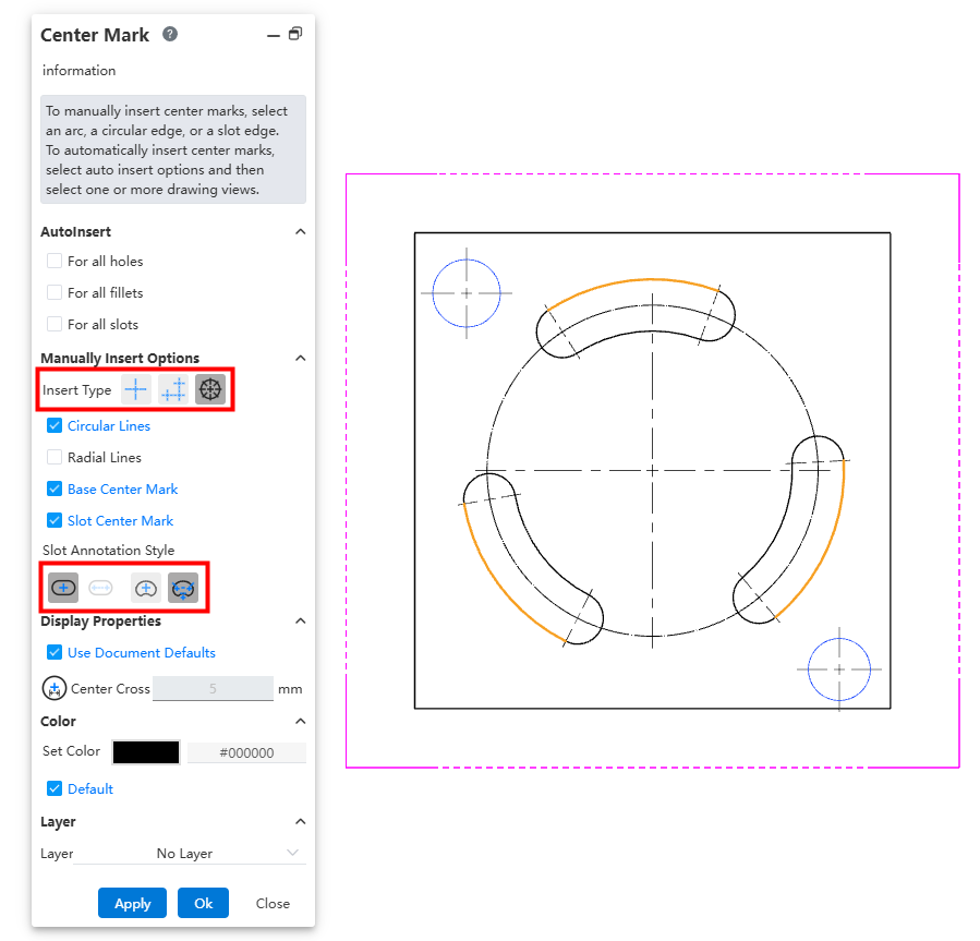
How to use:
Activate the Centerline command.
Select the projection-generated or sketch-generated element to be annotated.
Set the layout and slot annotation style.
Click OK to complete the centerline creation.
Explanations:
Linear and circular centerline annotations do not support mixed selection standards; they only support annotations for a single circle/arc, slot, or arc slot.
# Hole Callout
Hole Callout Command Function Enhancement: Multi-line text positioning adaptation supports different hole callout creation styles under various drawing standards.
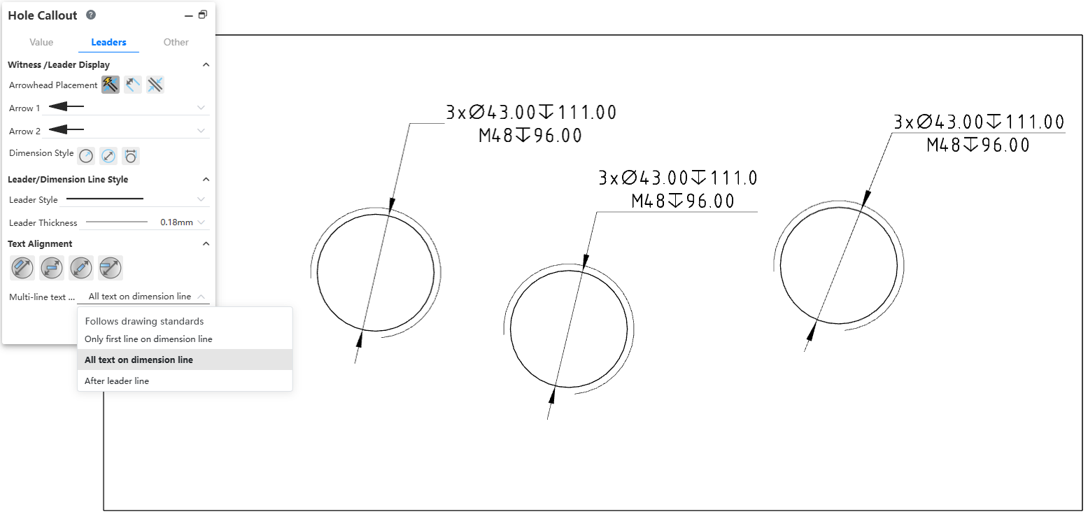
How to use:
In the system settings - Document Properties, set the drawing standard: GB, ISO, or ANSI.
After clicking the Hole Callout command, select the projected outline edge of the hole. The default position of the multiline text for hole callouts created under different standards will vary.
Click the Multiline Text Position dropdown in the Hole Callout panel to select your preferred multiline text position option.
Click OK to complete the hole callout creation.
# Piping
# Pipe Route Axis
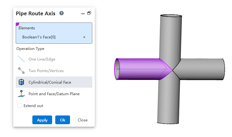
The pipe route Axis can be used in pipelines to set the path for the path line or define waypoints along the path, and the creation process is similar to that of a reference line.
How to use:
Create a part, draw the geometry, and then click "Pipe Route Axis".
Select geometric elements to determine the position.
The default length of the path axis depends on the selected elements. To modify the path axis length, adjust the extension parameters to control the length of the path axis.
Explanations:
A straight line/edge: Create a path axis based on a straight line or edge.
Two points/vertices: Create a path axis based on the connection line between two points.
Cylinder/Solid of revolution: Create a path axis aligned with the axis of a cylinder or solid of revolution.
Point and surface: Create a path axis passing through a point and perpendicular to a surface.
# Create Pipe
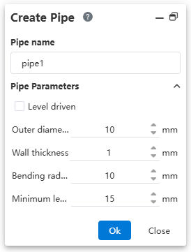
When creating the pipeline, display the pipeline parameters. You can preset pipeline parameters. After setting the parameters, enter the pipeline and then open the pipeline parameter function. The displayed values are consistent with those set at creation, and the process of creating the pipeline remains unchanged.
# Draw Route Line
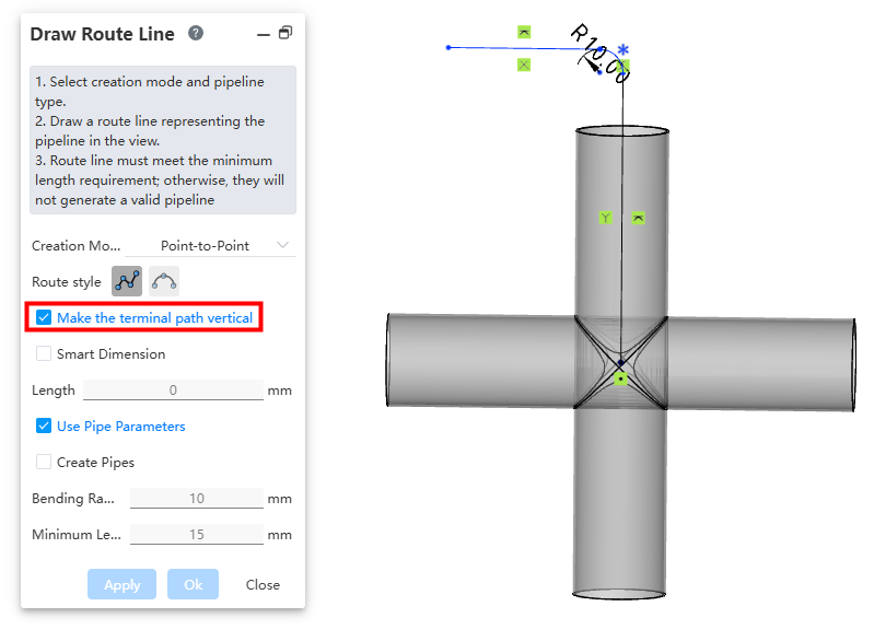
When drawing the point-to-point mode for path selection, add a checkbox option called "Endpoint Path Perpendicular." When the endpoint is a circular edge or connection point, selecting this option will ensure that the endpoint path line remains perpendicular to the connected line. If the option is unchecked, the behavior will be the same as in the CrownCAD 2026 R1 version.
# Pipe Auto Line
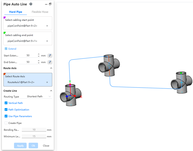
Automatic wiring distinguishes between hard and soft pipes using tabs. During automatic wiring, it supports picking multiple path axes and automatically wires in the order from start point to path axis 1 to path axis 2, and so on, up to the end point, according to the picked order.
How to use:
Insert the pipeline components.
Click the "Pipe Auto Line" command, then select the starting point and endpoint of the wire sequentially.
Choose whether to extend outward as needed.
Decide if you want to pick the path axis. If you do, you can set the direction for each path axis.
Select the wiring method.
Set the pipeline parameters and choose whether to create the pipe.
Dialog Box Controls Description:
Routr Axis:Pick one or more path axes existing in the current pipeline.
Reverse Direction: After selecting a path axis, use this option to adjust the direction in which the path line passes through the axis.
Flexible Hose
After creating or activating the pipe, automatically draw the hose path line between the two selected connection points.
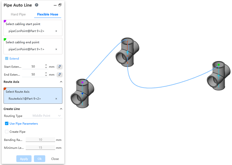
How to use:
Insert pipeline components or draw the path.
Click the "Pipe Auto Line" command to switch to Flexible hose.
Select the start and end points of the line separately.
Set the outward extension length.
Choose whether to pick the path axes as needed. When picking path axes, you can set the direction for each path axis.
Select the wiring method.
Set the pipeline parameters and choose whether to create the pipe.
Dialog Box Controls Description:
Start/End point: Can select all connection points and the endpoints of the current pipeline path line.
Extend Length:Additional front and back two lines are generated for the automatic path line along the rule-defined direction.
Route Axis: Can pick one or multiple path axes from the current pipeline.
Reverse Direction: After picking the path axis, this option can adjust the direction of the path line passing through the path axis.
Wiring Method: Can select midpoint, endpoint, or all points.
Use Pipeline Parameters:After checking,all subsequent dimension parameters for drawing the path are grayed out and use the data from “Pipeline Parameters.”If unchecked,the user can customize the pipeline parameters.
Create Pipe:When unchecked,only draw the path without creating the pipe;default is unchecked.When checked,generate the path and create the pipe according to subsequent options and values.The user can customize pipe parameters and whether to use level drive.
# Auto Bend Angle
Automatically add bend angles between all adjacent path lines in the path chain.
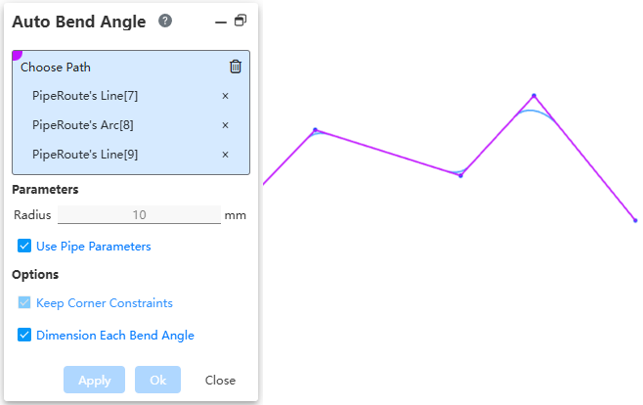
How to use:
Under the condition of activated path, draw multiple consecutive straight lines.
Click on "Auto Bend Angle", pick any path line, and fill the entire path.
After setting the fillet parameter, click OK to automatically generate a fillet at each corner.
Dialog Box Control Description:
Select Path: In the viewport, pick the path line to automatically fill the entire path it belongs to.
Use Pipe Parameters: Check this to make radius size unmodifiable. Default is 10mm. Uncheck this to customize the fillet size.
Maintain Corner Constraint: Keep the fillet tangent to both adjacent edges.
Label Each Fillet Size: When selecting multiple positions to set fillets, check this to label each fillet. Uncheck this to only label one fillet.
# BOM
# Pipe BOM
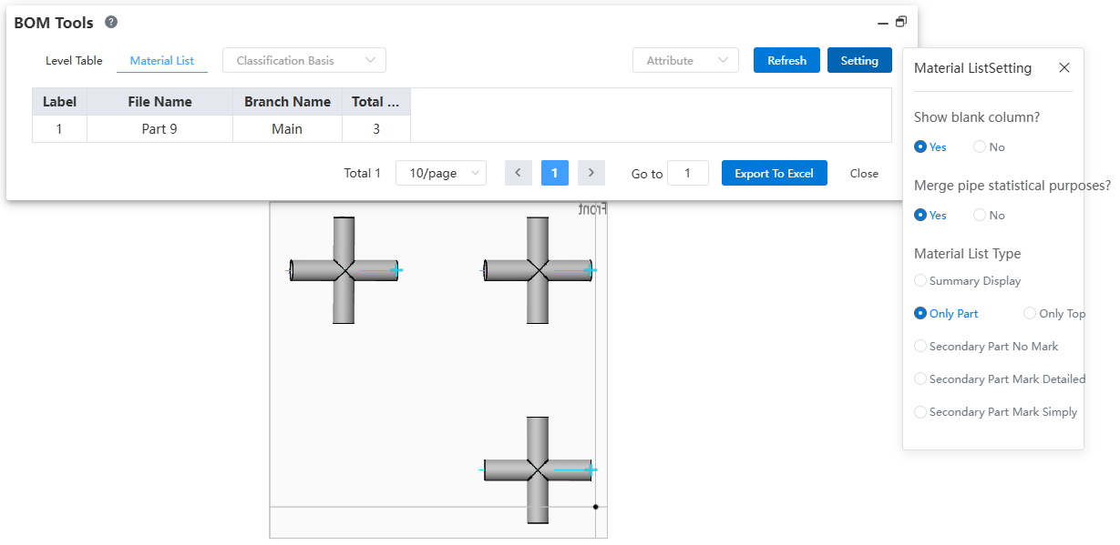
In the material list of the 【BOM Tool】, you can set whether to merge and count pipes. When merged, pipes of the same specifications are counted as one entry and the merged length is calculated.
← Applications 2026 R1 →