# Piping
# Pipe Route Axis
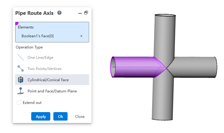
The pipe route Axis can be used in pipelines to set the path for the path line or define waypoints along the path, and the creation process is similar to that of a reference line.
How to use:
Create a part, draw the geometry, and then click "Pipe Route Axis".
Select geometric elements to determine the position.
The default length of the path axis depends on the selected elements. To modify the path axis length, adjust the extension parameters to control the length of the path axis.
Explanations:
A straight line/edge: Create a path axis based on a straight line or edge.
Two points/vertices: Create a path axis based on the connection line between two points.
Cylinder/Solid of revolution: Create a path axis aligned with the axis of a cylinder or solid of revolution.
Point and surface: Create a path axis passing through a point and perpendicular to a surface.
# Create Pipe
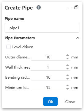
When creating the pipeline, display the pipeline parameters. You can preset pipeline parameters. After setting the parameters, enter the pipeline and then open the pipeline parameter function. The displayed values are consistent with those set at creation, and the process of creating the pipeline remains unchanged.
# Draw Route Line
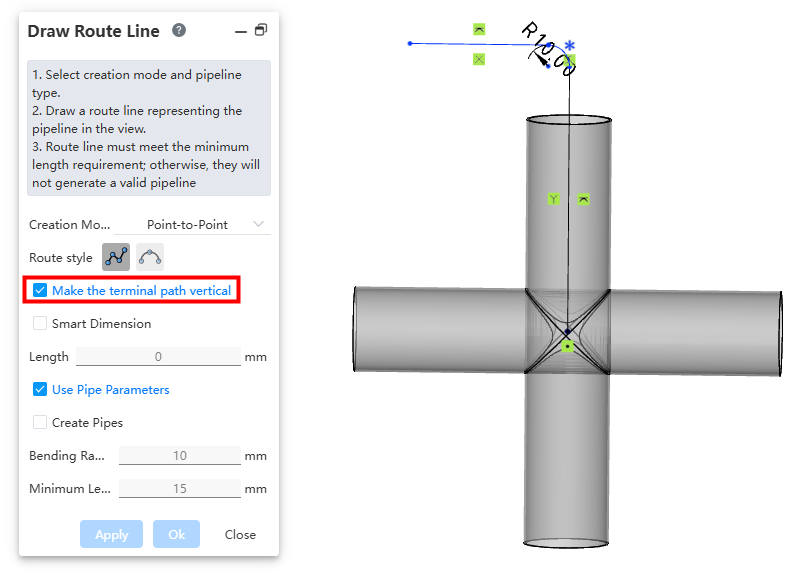
When drawing the point-to-point mode for path selection, add a checkbox option called "Endpoint Path Perpendicular." When the endpoint is a circular edge or connection point, selecting this option will ensure that the endpoint path line remains perpendicular to the connected line. If the option is unchecked, the behavior will be the same as in the CrownCAD 2026 R1 version.
# Pipe Auto Line
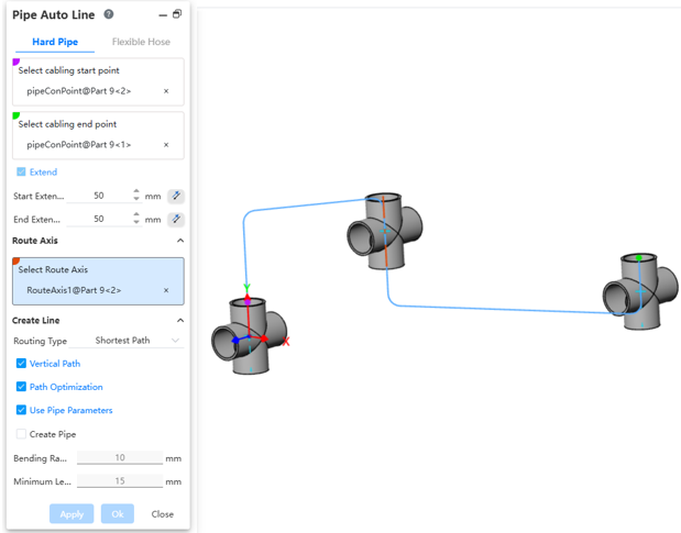
Automatic wiring distinguishes between hard and soft pipes using tabs. During automatic wiring, it supports picking multiple path axes and automatically wires in the order from start point to path axis 1 to path axis 2, and so on, up to the end point, according to the picked order.
How to use:
Insert the pipeline components.
Click the "Pipe Auto Line" command, then select the starting point and endpoint of the wire sequentially.
Choose whether to extend outward as needed.
Decide if you want to pick the path axis. If you do, you can set the direction for each path axis.
Select the wiring method.
Set the pipeline parameters and choose whether to create the pipe.
Dialog Box Controls Description:
Routr Axis:Pick one or more path axes existing in the current pipeline.
Reverse Direction: After selecting a path axis, use this option to adjust the direction in which the path line passes through the axis.
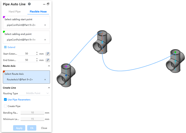
Flexible Hose
After creating or activating the pipe, automatically draw the hose path line between the two selected connection points.
How to use:
Insert pipeline components or draw the path.
Click the "Pipe Auto Line" command to switch to Flexible hose.
Select the start and end points of the line separately.
Set the outward extension length.
Choose whether to pick the path axes as needed. When picking path axes, you can set the direction for each path axis.
Select the wiring method.
Set the pipeline parameters and choose whether to create the pipe.
Dialog Box Controls Description:
Start/End point: Can select all connection points and the endpoints of the current pipeline path line.
Extend Length:Additional front and back two lines are generated for the automatic path line along the rule-defined direction.
Route Axis: Can pick one or multiple path axes from the current pipeline.
Reverse Direction: After picking the path axis, this option can adjust the direction of the path line passing through the path axis.
Wiring Method: Can select midpoint, endpoint, or all points.
Use Pipeline Parameters:After checking,all subsequent dimension parameters for drawing the path are grayed out and use the data from “Pipeline Parameters.”If unchecked,the user can customize the pipeline parameters.
Create Pipe:When unchecked,only draw the path without creating the pipe;default is unchecked.When checked,generate the path and create the pipe according to subsequent options and values.The user can customize pipe parameters and whether to use level drive.
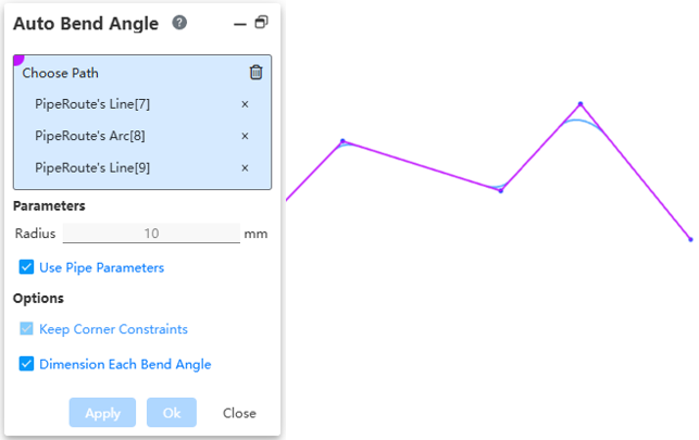
# Auto Bend Angle
Automatically add bend angles between all adjacent path lines in the path chain.
How to use:
Under the condition of activated path, draw multiple consecutive straight lines.
Click on "Auto Bend Angle", pick any path line, and fill the entire path.
After setting the fillet parameter, click OK to automatically generate a fillet at each corner.
Dialog Box Control Description:
Select Path: In the viewport, pick the path line to automatically fill the entire path it belongs to.
Use Pipe Parameters: Check this to make radius size unmodifiable. Default is 10mm. Uncheck this to customize the fillet size.
Maintain Corner Constraint: Keep the fillet tangent to both adjacent edges.
Label Each Fillet Size: When selecting multiple positions to set fillets, check this to label each fillet. Uncheck this to only label one fillet.