
# Sheet Metal
# Base Flange
The Base Flange feature has added "Up to Vertex" and "Up to Surface" options to flexibly control the termination condition of the Base Flange.
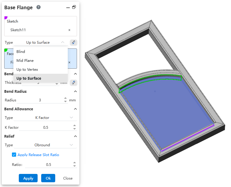
Usage:
Click the "Base Flange" command to open the dialog box.
Pick a non-closed profile sketch.
Select the option "Up to Vertex" / "Up to Surface".
Pick the point / face to terminate the extrusion.
Click OK to complete creation.
# Edge Flange
# Up to Vertex
The Edge Flange feature has added the "Up to Vertex" option to flexibly control the termination condition of the Edge Flange.
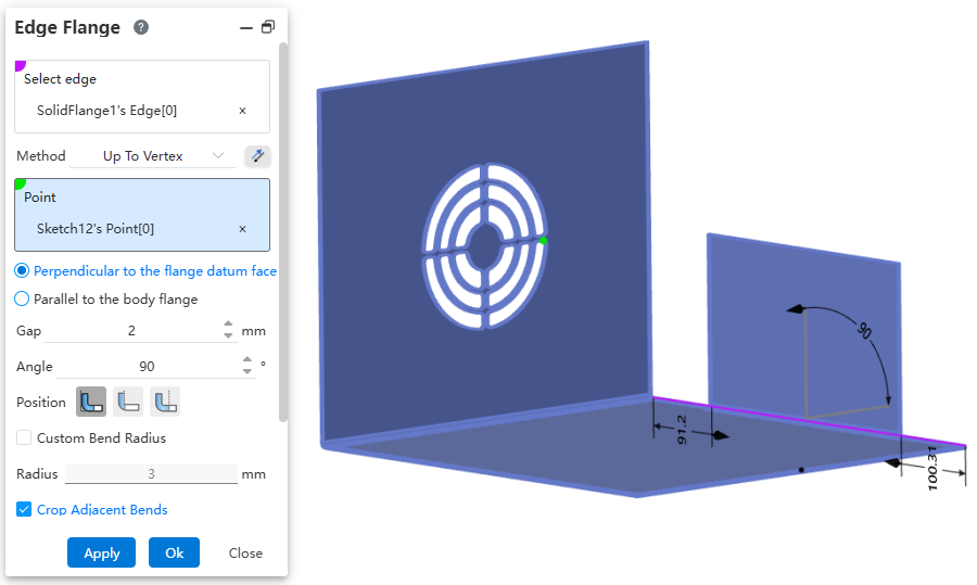
Usage:
Click the "Edge Flange" command to open the dialog box.
Pick an edge.
Select the option "Up to Vertex".
Pick the point to terminate the extrusion.
Set the point's action direction to "Perpendicular to the flange datum face" / "Parallel to the body flange".
Click OK to complete creation.
Dialog Box Control Descriptions:
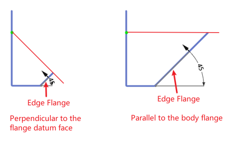
Perpendicular to the flange datum face: The action direction of the selected point is perpendicular to the Edge Flange.
Parallel to the body flange: The action direction of the selected point is parallel to the Base Flange.
# Apply Release Slot Ratio
The Edge Flange feature has added the Apply Release Slot Ratio function, allowing control over the release slot size via a ratio relative to the sheet metal thickness.
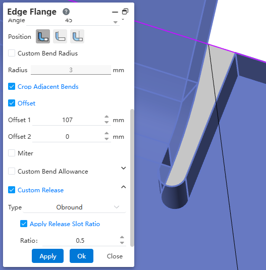
Usage:
Click the "Edge Flange" command to open the dialog box.
Pick an edge.
Set the Offset so that release slots appear on both sides of the flange.
Check "Custom Release Slot", select the release slot type as "Rectangular/Obround", and check "Apply Release Slot Ratio".
Set the release slot ratio.
Click OK to complete creation.
Note: Ratio Value = Release Slot Width / Sheet Metal Thickness, Release Slot Length = Release Slot Width.
# Cut Vent
The Cut Vent command has been added to quickly generate vents on the model.
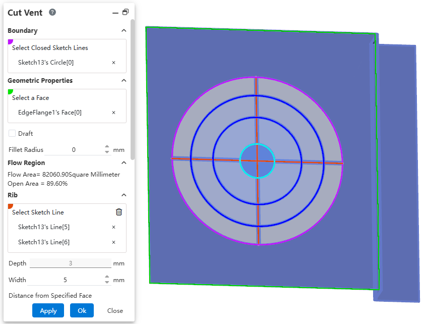
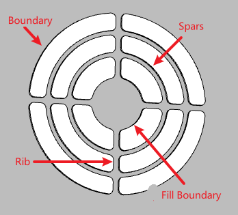
Usage:
Click the "Cut Vent" command to open the dialog box.
Select the boundary sketch to specify the external boundary of the vent.
Select the face where the vent will be created.
Select "Rib, Spars, or Fill Boundary" as needed.
Set parameters such as fillet radius.
This function involves many parameters. After configuration, click "Add or Update Favorite" to save the settings. Subsequently, parameters can be reused directly by selecting the favorite.
Click OK to complete creation.
Dialog Box Control Descriptions:
Boundary:
- Select Sketch Segments: Select sketch lines representing the vent boundary, supporting multiple lines combined into a closed profile.
Geometry Properties:
Select a Face: Select the face to place the vent.
Draft: Check to enable draft settings.
Fillet Radius: Sets the fillet radius at the intersections between the vent Boundary, Rib, Spars, and Fill Boundary. Set to 0 to add no fillet.
Flow Area: Automatically calculates the flow area of this vent based on the preview.
Rib:
Select Sketch Segments: Select sketch lines representing the Rib.
Depth: Sets the Rib depth. On sheet metal bodies, Rib depth is fixed equal to sheet metal thickness.
Width: Sets the Rib width.
Distance from Specified Face: Sets the offset distance from the Rib's starting position to the face.
Spars, Fill Boundary: Similar to Rib, the related parameters control "Spars" and "Fill Boundary" respectively.
Favorites:
Dropdown: Used to select saved parameters.
Add or Update Favorite: Used to create a new favorite with current parameters or update an existing favorite.
Delete Favorite: Used to delete an existing favorite.