
# Sketch
# Spline
Each pass-through point on the Spline supports adjusting control handles to precisely control the curve shape.
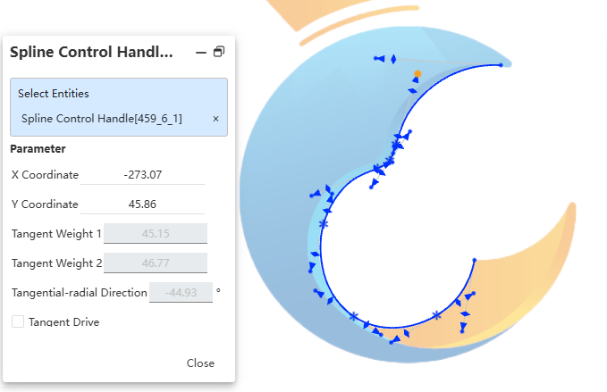
Usage:
- Draw a Spline.
- Select the Spline. Control handles will appear on each pass-through point.
- Drag the control handles to modify the curve shape.
Note 1: Selecting the curve displays all control handles on it. Deselecting the curve hides unadjusted control handles.
Note 2: Hold the Alt key while dragging a control handle to move the handles on both sides synchronously.
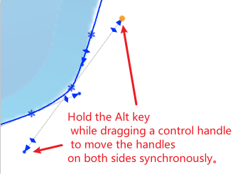
Curve Control Handle Description:

Circular Control Handle: Drag to adjust the handle's length and direction.
Triangular Control Handle: Drag to adjust the handle's length without changing direction.
Diamond-shaped Control Handle: Drag to adjust the handle's direction without changing length.
Note: Gray control handles indicate an inactive state (i.e., not manually adjusted). Blue control handles indicate an active state (i.e., manually adjusted).
Dialog Box Control Descriptions:
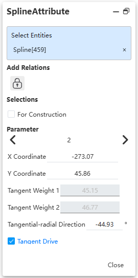
Add Constraint: Displays available constraints. Click to add the constraint to the selected element.
Reference Line: Controls whether the current element is set as a reference line.
Index: Displays which point on the curve corresponds to the current parameter. Click the left/right arrows to switch points.
Coordinates X, Y: Displays the coordinates of the current point.
Tangent Weight 1, 2: Displays the weights of the control handles on both sides of the current point.
Tangent Radial Direction: Displays the direction of the current point's control handle.
Tangent Drive: Check this option to manually set the control handle direction in the dialog box. Dragging other control handles will not affect this handle's direction. This option is automatically checked when dragging control handles in the viewport.
# Real-time Preview
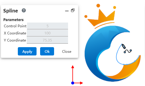
When drawing a Spline, a real-time curve preview is displayed based on the cursor position.
# Line
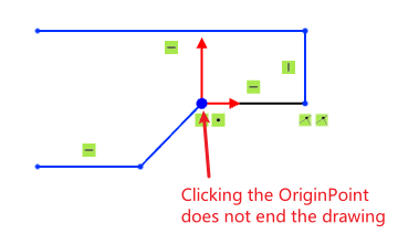
When drawing a Line, clicking the OriginPoint does not end the drawing; you can continue drawing lines.
# Trim
# Keep the trimmed elements as reference lines
Supports the "Keep the trimmed elements as reference lines" option.
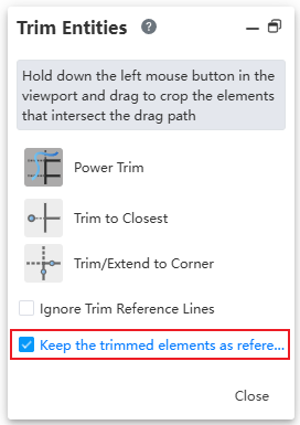
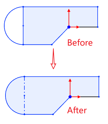
Check this option to trim without deleting the lines. Instead, the lines are converted to reference lines, which helps preserve sketch constraints.
# Trim/Extend to Corner
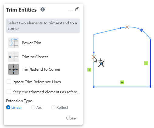
The "Trim/Extend to Corner" feature has been added. It supports one-click trimming to form a corner between two sketch lines, eliminating the need for multiple trim/extend operations. This makes sketch trimming more flexible and effectively improves modeling efficiency.
Usage:
Open the Trim command.
Select the "Trim/Extend to Corner" mode.
Click the curve in the viewport to create a corner. An X marker appears at the click location.
Select the other curve in the viewport to create a corner. Another X marker is displayed during preview.
Click to create the corner.
Note: When the selected curves have multiple intersections, the corner will be created at the intersection point closest to the X marker.
Extension Type Description:

Linear: Extends along the tangent direction of the Spline at the endpoint to be extended.
Arc: Extends along the selected Spline at the endpoint to be extended, maintaining curvature continuity.
Reflect: Extends the curve as a mirror image. The mirror plane is perpendicular to the curve plane, positioned at the location perpendicular to the curve tangent at the endpoint to be extended.
# Check Sketch Validity
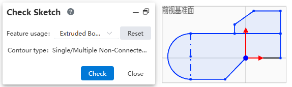
The "Check Sketch" command has been added. Before creating or modifying sketches for features (e.g., Extrude, Revolve, etc.), run this function first to check whether the sketch meets modeling requirements or contains potential issues.
Usage:
Open the Check Sketch command.
In Feature usage, select the type of feature to which this sketch will be applied.
Click "Check". The system automatically checks whether the sketch can be applied to the selected feature.
If the check fails, a prompt message will appear explaining the cause of the error.
Click the OK button in the prompt message. The system automatically opens the "Repair Sketch" command to perform repairs.
Dialog Box Control Descriptions:
Feature usage: Select the type of feature to which this sketch will be applied.
Reset: Click to reset the Feature usage.
Contour type: Displays the contour type corresponding to the feature based on the selected feature.
Check: Click to check whether the sketch can be applied to the selected feature.
# PointOnPlane Constraint
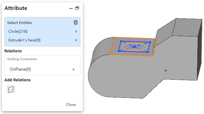
A new PointOnPlane constraint has been added to 3D Sketches. It is used to constrain sketch lines, points, or curves to lie fully on a plane.
Usage:
In the 3D Sketch, select the sketch elements to constrain: 3D Sketch lines, curves, or arcs.
Hold the Ctrl key and select the plane to constrain to.
Click the PointOnPlane button in the Add Constraint section of the Property Dialog. The sketch elements are constrained to the plane.