# Parts and Features
# Extruded Boss/Base / Extruded Cut
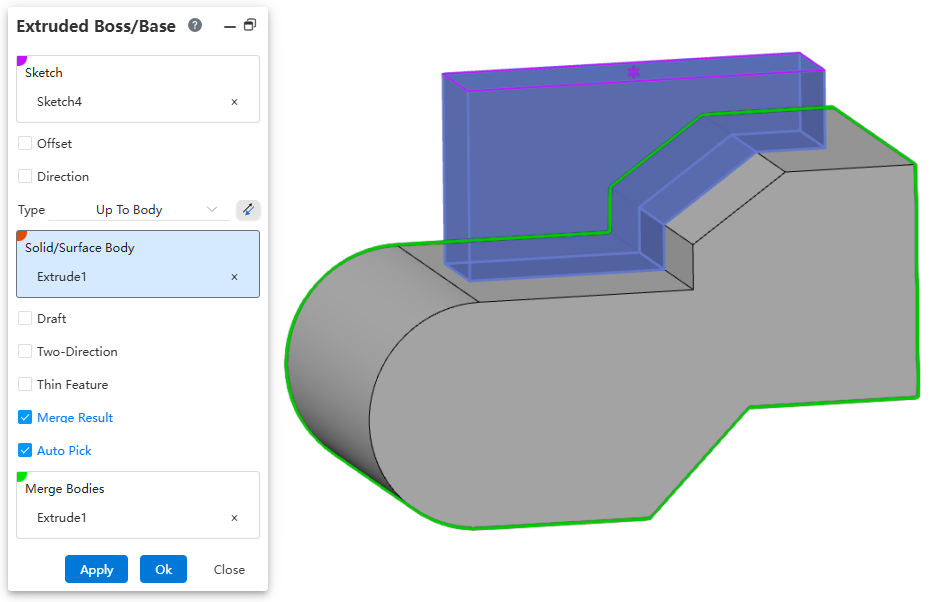
The "Up To Body" option has been added for Extruded Boss/Base and Extruded Cut. This option is primarily used in scenarios where the feature needs to terminate on multiple faces of a single body.
Usage:
Open the Extruded Boss/Base or Extruded Cut command.
Select the sketch.
Set the option to "Up To Body".
Select the target body/surface.
Click OK to complete the creation.
# Plane
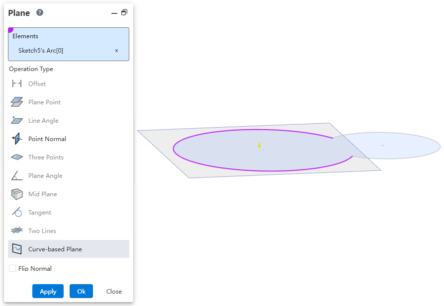
A new Curve-based Plane option has been added, supporting the creation of a Plane using a curve that belongs to a single plane.
Usage:
Open the Plane command.
Select Curve-based Plane for the operation type.
Pick a curve belonging to a single plane. A Plane preview will be displayed.
Click OK to complete the creation.
# Hole Wizard
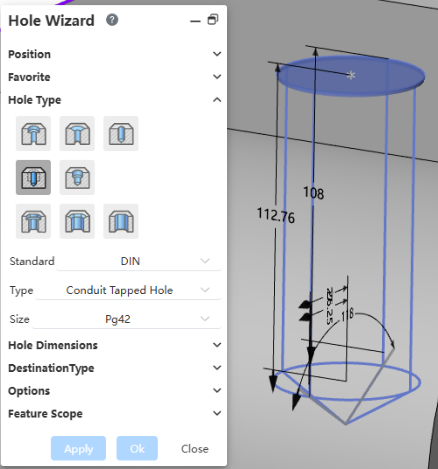
The Hole Wizard standards have been expanded, adding "DIN, JIS, ANSI Metric" standards.
# Pattern Mirror
The Pattern Mirror function supports recording the checkbox state of the Geometry Pattern option.
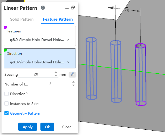
Checking Geometry Pattern can significantly improve feature creation speed, while unchecking Geometry Pattern enables Pattern Mirror in complex scenarios.
You can set the checkbox state according to modeling requirements. The system will automatically record your last setting to avoid repeated configuration.
# Delete Face
The Delete Face command has added a Hole type, enabling batch deletion of holes that meet the conditions.
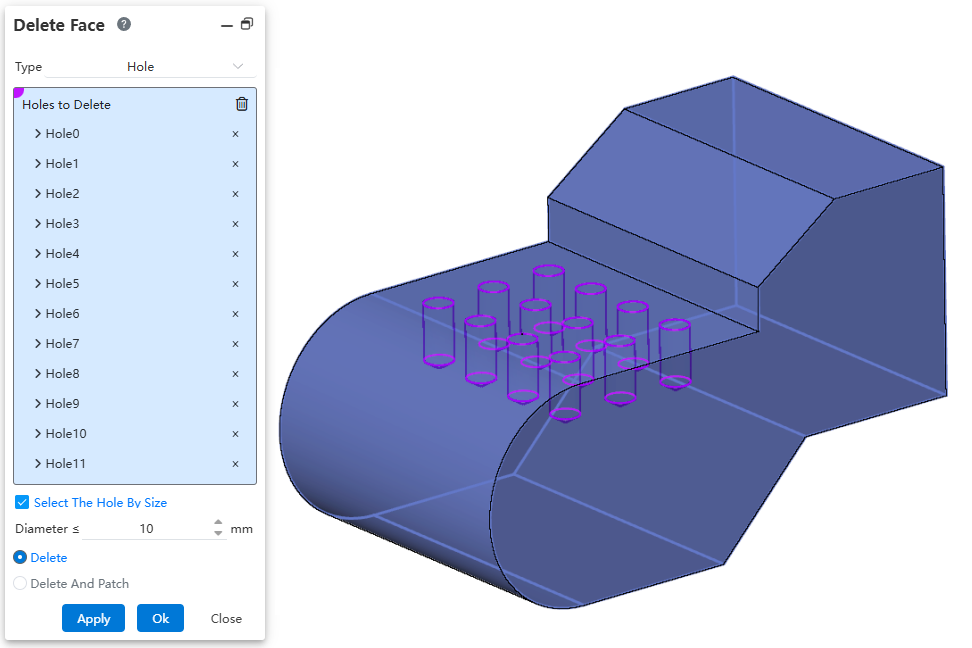
Usage - Manual Selection:
Open the "Delete Face" command.
Change the type to "Hole", and uncheck "Select The Hole By Size".
Click or box-select holes in the viewport to pick them.
Holes of the same size as the selected hole but not picked will be highlighted in green for selection.
Set "Delete and Patch" to ensure the solid can be patched after deleting the hole.
Click OK to complete deletion.
Usage - Automatic Selection:
Open the "Delete Face" command.
Change the type to "Hole", and check "Select The Hole By Size".
Set the hole diameter parameter.
Click or box-select holes in the viewport; all holes less than or equal to the specified diameter will be automatically picked.
Set "Delete and Patch" to ensure the solid can be patched after deleting the hole.
Click OK to complete deletion.
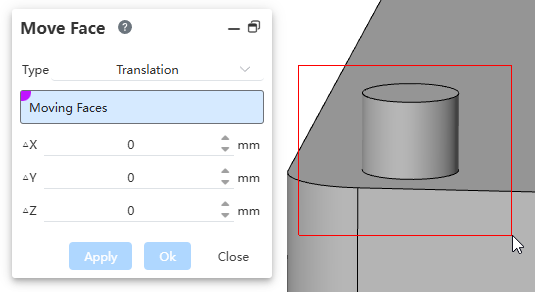
# Move Face
The Move Face command supports box selection of faces. For scenarios where multiple faces need to be moved simultaneously, box selection allows for quick selection, improving modeling efficiency.