# Thickness Analysis
The [Thickness Analysis] command can identify the thin and thick areas of the parts, determine the different thicknesses of the parts, and assist the designer in evaluating the product structure.
How to use:
1) Click the [Thickness Analysis] command of the evaluation module.
2) Set the target thickness and other parameters.
3) Select the entity to analyze as needed.
4) Click Calculate and wait for the calculation to complete to view the results.
5) Click Close to finish.
Dialog box element description:
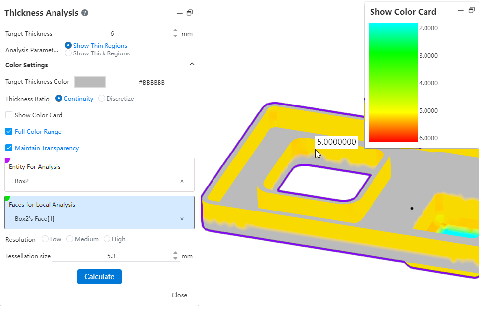
Target Thickness: Enter a target thickness value that will be used as the standard for analysis.
Display Thin area: The area below the target thickness is displayed in the viewport.
Display Thick area: Display areas less than and greater than a specific thickness range, and display thin area is mutually exclusive, both are required.
Thick area restriction: This item is displayed only when the display thickness area is selected. Enter the maximum thickness to calculate the area that is not in the range.
Make the corners as zero thickness treatment: After checking, the corners of the parts will not be regarded as weak when calculating, but as consistent thickness treatment.
Target thickness color: This color is the color displayed to meet the thickness target area.
Thickness ratio: You can choose to display the color in a continuous or discrete manner.
Display color card: The color card that displays the thickness ratio on the right side of the dialog box when checked. The number of discrete values can be set in the color card when the thickness ratio is selected discretely.
Full color range: The product provides a default gradient range color, uncheck this option to customize the color.
Minimum Thickness color: This item is displayed only when the full color range is unchecked. Together with the target color, the color displayed in the area is controlled.
Retain transparency: This option takes effect when the selected entity is set to a transparent appearance.
Entity to be analyzed: This option is displayed only when there are 2 or more entities in the part, and the thickness analysis calculation can be performed after the entity is specified.
Face of local analysis: This option is optional, and multiple faces on the same entity can be picked up. The faces of the entity can be specified for analysis. The whole entity is calculated by default when no faces are picked up, and only the picked faces are calculated when picking up.
Resolution: The higher the resolution, the smaller the surface, the more accurate the result, but at the same time the calculation time will be longer. Low: The maximum value of the surrounding box /503. Medium: Maximum value of encircling box /502. High: Max of the encircling box /50.
laking: The value is displayed at the selected resolution after picking up the flaking, and the value can also be entered. Supported input range: [0.5, the maximum value of the surrounding box /50*3].
Note:After opening the thickness analysis, the curves and surfaces in the parts will automatically become hidden, and the display will be restored after closing the function.