# Data Exchange
Data exchange is used for data sharing of different types of files, either by importing files from other applications into the CrownCAD software or by exporting multiple format models for use by other applications. The interface for importing outside the project, inside the project and inside the document is shown in the figure below:


# Import
The imported files include parts, assembly, engineering drawings, pictures and videos, and the format is supported
Standard version:
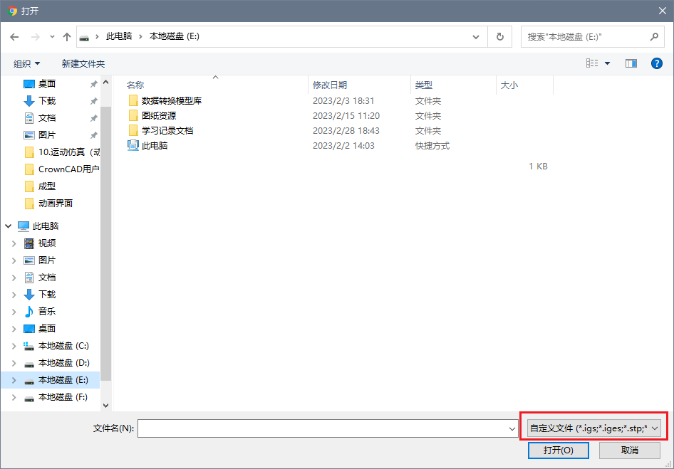
.igs, .iges, .stp, .step,Catia(.catproduct, .catpart), ParaSolid(.x_t), SolidWorks(.sldasm, .sldprt,) NX(.prt), PTC(.asm, .prt),.stl, .obj,.dwg, .dxf, .pdf, .zip, .rar, .png, .jpg, .jpeg, .bmp, .gif, .mp4, .svlx
Pro Edition:
.igs, .iges, .stp, .step, Catia(.catproduct, .catpart), ParaSolid(.x_t, .x_b), SolidWorks(.sldasm, .sldprt, .slddrw),SolidEdge( .par), NX(.prt),Inventor(.iam, .ipt) PTC(.asm, .prt,.drw), .stl, .obj, .ifc,.cgr,3dm,.3dxml,.rvm, .jt, .sat, .rvt, .dwg, .dxf, .zip, .rar, .pdf, .png,.jpg, .jpeg, .bmp, .gif, .mp4, .svlx, ppt(.ppt, .pptx), word(.doc, .docx),Emp,emn,vda
Tips to use:
1)Import up to 10 files at a time, optionally compressed into a zip.
2)For Standard Edition users, the maximum number of uploads per day is 10, and a maximum of 20M documents can be uploaded at one time.
3)The file name can be Chinese, English or numeric symbols;
4)Import a large file, which may take a long time.
# Import Setting
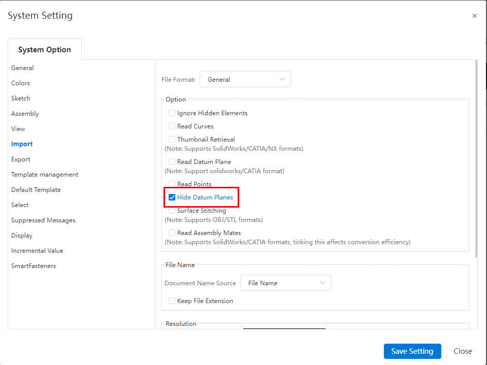
Click System Settings - System Options - Import to go to Import Settings where you can set the import formats.

Click Import - Import file command and click Import Settings on the Import interface to also enter the Settings dialog box.
# File Format - General
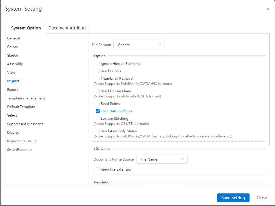
【Ignore Hidden elements】 : Controls whether to read hidden entities/surfaces/curves in the assembly file.
【Read curves】 : Controls whether to read curves.
【Read the original model file thumbnail】 : Control whether to read the original model file saved in the thumbnail, support SolidWorks/CATIA/NX format.
【Read point】 : Control whether to read the point.This feature supports reading spatial points from Creo, UG, CATIA, and SolidWorks models. These points are then imported as 'datum points'.
【Hide datum】 : Controls whether the datum of the imported model is displayed or hidden by default.
【Stitch mesh】 : Select stitch to do as a whole import, there is only one mesh in the feature panel; Without stitching, the grid is imported in blocks, and each grid in the feature panel is regarded as a grid.
【Read constraint】 : Controls whether to import the assembly fit relationship, which may affect the conversion efficiency.
【Document name source】 : A file in the format of CATIA. The component name recorded in the file may be different from the file name. When importing such files in CC, it is supported to read the part name information recorded in the file, and you can choose to use "file name" or "part name recorded in the file" as the name of the part document after import.
【Retain file name extension】 : When the document name source is "file name", control whether to retain the file name extension.
【Resolution】 : Set the precision of the imported model, only for non-grid class models.
# File Format - NX
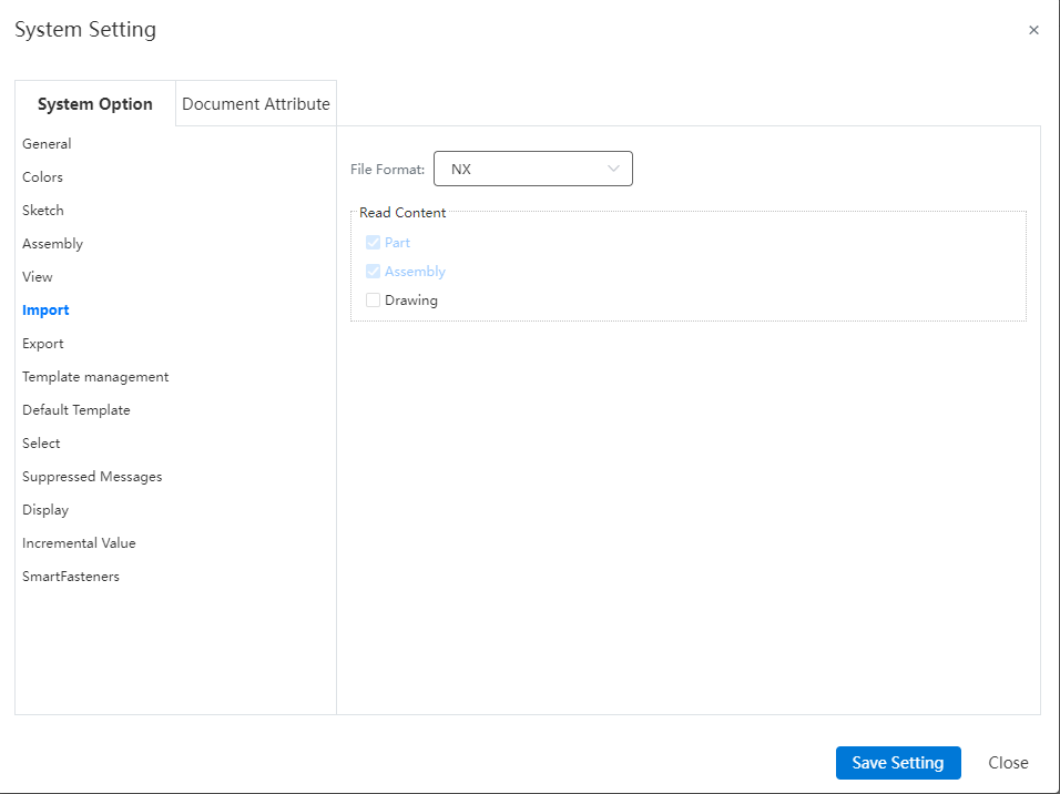
[Engineering drawing] : When importing NX file, the engineering drawing in the file is read by default.
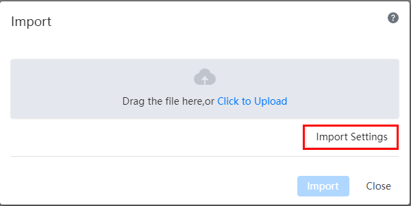
# Import Interface
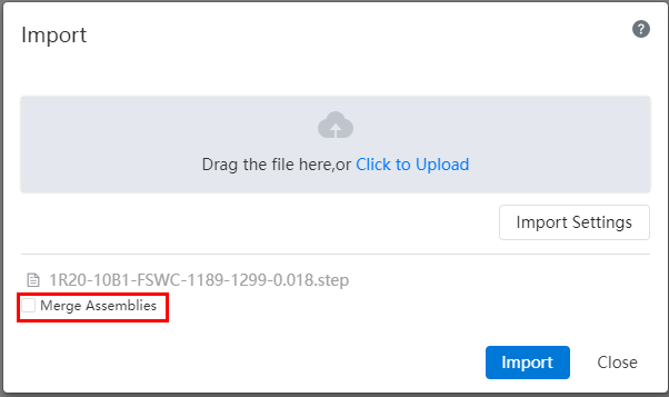
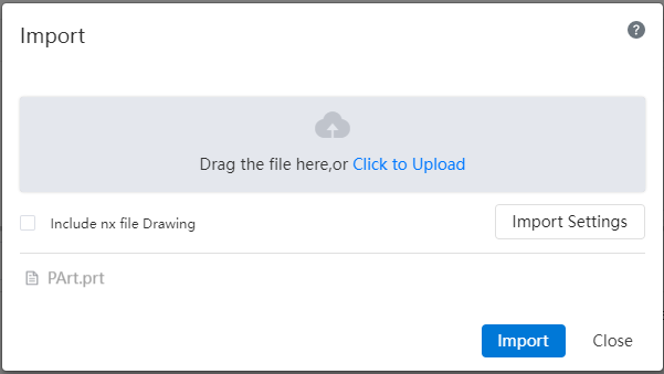
Click the import-Import file command to bring up the Import dialog box:
You can drag the file to the dialog box, or click Upload, specify the file path and filter the file format, click Import after upload, start the upload and conversion operation, the process can be viewed in [Task].
# Assembly Import
Multiple file assembly model, you can package all model files into a zip file, and make the zip file name consistent with the top assembly file name, the default conversion of the top assembly after uploading.
If the assembly is inconsistent at level 2, the user needs to manually select the document that needs to be converted.
When importing an assembly in intermediate format, the option "Do you want to merge the assembly?" will be prompted:
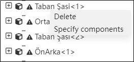
- The missing parts in the import assembly can be specified manually by right-clicking the menu:
- Right-click a missing part in the feature panel to choose to specify the part or remove it.
Select the specified part from the menu and the "Specify Part" dialog box will pop up.
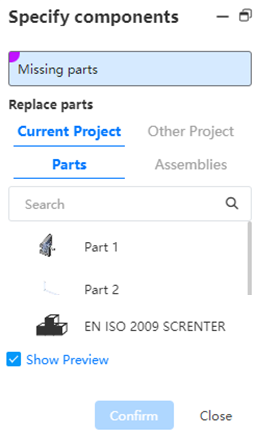
- If there is a document with the same name as the missing part within the current project, the part or assembly with the same name within the current project is selected by default.
- If there is no part with the same name, the part or assembly of the current project is displayed by default. If the missing part is an assembly, the assembly of the current project is displayed by default.
The "Show Preview" function makes the preview of the selected part appear in the location of the missing part in the viewport. This item is not checked by default.
Select the part and click OK. The missing part will be replaced by the selected part.
# Drawing Import
Support to read NX, SolidWorks, Creo, CATIA drawings.
- When uploading prt file, add "include NX file engineering drawing" option, if checked, convert, if not checked, do not convert; Checked is only valid for the current Settings, and the conversion is performed according to the Settings in "Import Settings" by default.
- List of tasks:
- When uploading: Only one record appears in the task list;
- During and after conversion: Display two records "xxx.prt" and "XXX.prT.DWG";

- The "Cancel button" can be used to cancel the conversion model or engineering drawing respectively;
- After successful conversion, you can use the open button to jump to the corresponding model or project drawing respectively;
- If there is no project drawing in the prt file, and the user has checked the project drawing, the pop-up prompt "No dwg read". The engineering drawing task status displays "Not read".
- Creo drawings must be uploaded at the same time as the drawings and the 3D model file they reference in order to convert correctly, it is recommended to package the file as a compressed package and upload it.
# Folder Import
For files that need to be converted in batches, you can directly upload the folder, and the system will import all files in the folder. For unsupported formats, the system will prompt "This type of file is not supported" when opening.


# Datum Import
Support to import SOLIDWORKS, CATIA format model datum plane.
Usage:
Open System Settings and click System Options-Import
Check Read datum (not checked by default)
# Export
# Export part
Export the parts, File format:IGES(.iges)、STEP(.step)、NX(.prt)、CATIA(.catpart)、SolidWorks(.sldprt)、ParaSolid(.x_t)、STL(.stl)、OBJ(.obj)、IFC(.ifc)、X_B(.x_b)、FBX。
Click  the icon to bring up the drop-down menu, select the options
  in the menu, the pop-up dialog box is as follows:
Custom naming of exported documents is supported.
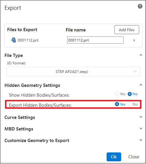
You can choose whether to export the geometry in a hidden/uninstalled state.
In the "Restore Hidden Bodies/Surfaces to Display State" settings under hidden geometry, selecting "Yes" will display the relevant geometry and export it.
When "Restore Hidden Bodies/Surfaces to Display State" is selected as "No," if you check "Yes" for the "Export Hidden Bodies/Surfaces" option, the hidden geometry will be exported.
# Export Assembly
Export assembly, Support the IGES file format IGES(.iges)、STEP(.step)、NX(.prt)、CATIA(.catpart)、SolidWorks(.sldasm)、、STL(.stl)、OBJ(.obj)、IFC(.ifc)、X_B(*.x_b)、FBX。
- Click the icon to bring up the menu, select the options in the menu, the pop-up dialog box is as follows:
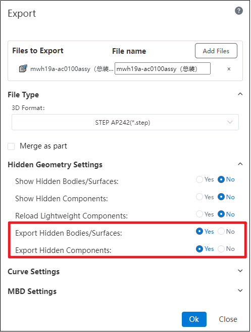
Merge as parts: Check to merge assembly as one part export. When this is checked, you can select the geometry you want to save.
- All Parts: Export all parts.
- External faces: Export only the external faces of the parts, ignoring the internal elements.
Hide Geometry Settings:
In the "Restore Hidden Bodies/Surfaces to Display State" and "Restore Hidden Parts to Display State" options under hidden geometry settings, selecting "Yes" will display the relevant geometry and parts, which will then be exported.
When "Restore Hidden Bodies/Surfaces to Display State" and "Restore Hidden Parts to Display State" are selected as "No," if you check "Yes" for the "Export Hidden Bodies/Surfaces" and "Export Hidden Parts" options, the hidden geometry and parts will be exported.
# Export Drawings
Export engineering drawing, file format support DWG, DXF, PDF; DWG, DXF support Release14, 2000, 2004, 2007, 2010, 2013, 2018.
Click the icon to bring up the drop down menu, select the options in the menu, the pop-up dialog box is as follows:
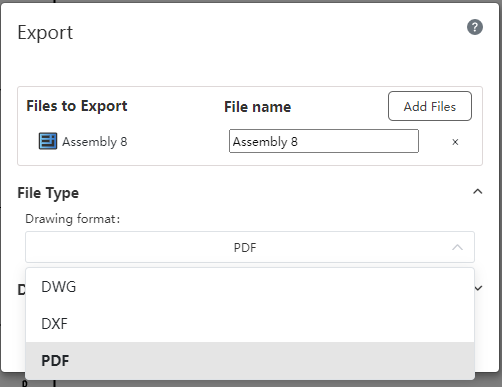
When exporting the PDF, the view of the coloring style in the project drawing will keep the display model color.
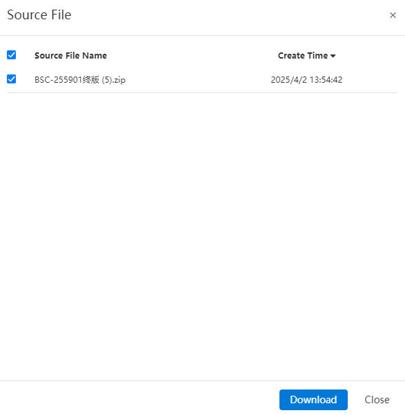
# Source File
Click on the source file , it displays all downloadable imported files of the current project. After selection, the user can download the chosen file to their local device in its original format.
# Export to Geometry
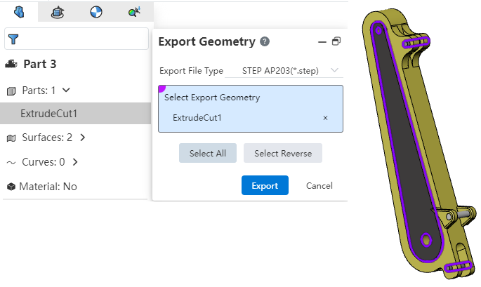
To utilize the "Export to Geometry" function, you can customize which solids, surfaces, and other geometries are included in the exported file.
Method 1:
Right-click on the geometry to be exported.
Click "Export Geometry."
Select the geometry elements and output format for export.
Click "Export" to complete the operation.
Method 2:
From the "Import/Export" dropdown menu, select "Export Command."
Click the button labeled "Select Geometries for Export."
Choose the desired geometry elements and specify the file format.
Click "Export" to finalize the process.
Dialog Box Controls Explanation:
Output Format: Specifies the file format used during export.
Select Geometry Elements: Allows you to choose which geometries will be exported.
All Select: When clicked, selects all geometry elements within the document for export.
Inverse Select: Toggles selection state of all geometric entities (selected becomes unselected and vice versa).
# Export Curves
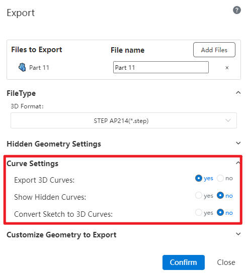
This feature supports exporting curves simultaneously while exporting models and allows detailed settings for the exported curves.
Control Descriptions:
Export Spatial Curves: A control to decide whether or not to export curves.
Convert Hidden Spatial Curves to Display State: A control determining if hidden curves will be displayed after export.
Convert Sketches to Spatial Curves for Export: Determines whether sketches are exported as spatial curves.
Additional Notes:
The Parasolid (x_b, x_t*) format requires enabling the "Convert Hidden Spatial Curves to Display State" option.
In IGES format:Solids/surfaces are exported while maintaining their hidden state when applicable.When exporting components, hidden parts are excluded from export.
Sketches can only be converted into spatial curves for export if they are in a visible state.
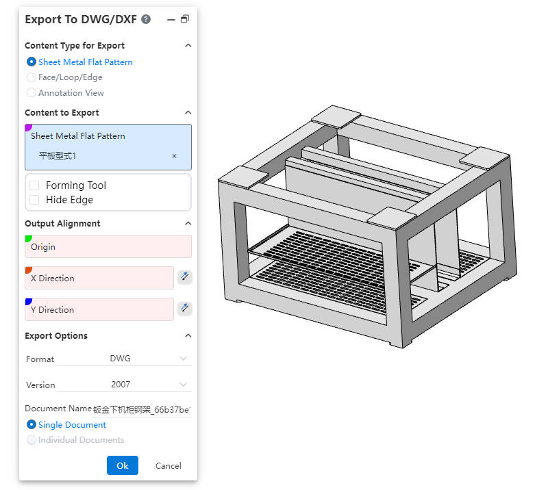
# Export DWG/DXF
This feature enables the one-click export of engineering drawings containing the outer contours of sheet metal flat layout models.
How to use:
Click "Export DWG/DXF" in the Import/Export drop-down menu.
Select the output content type, content, alignment, file format, etc.
Click OK to open a preview window.
In the preview window, select unwanted lines and click "Delete" to remove them.
When exporting multiple contents, use the left/right buttons to switch drawings.
Click OK in the preview window to complete the export.
Dialog Box Control Descriptions:
Output Content Type: Used to select the type of content to be exported.
Sheet Metal Flat Layout View: Exports sheet metal flat layout views. Only available for parts with sheet metal features. If multiple sheet metal components exist, you can export flat layout views for each separately.
Face/Loop/Edge Lines: Select mutually parallel faces, edges, or loops, and project them onto the same plane to output as an engineering drawing.
Annotation View: Select one or more view directions to generate corresponding views based on the selected directions.
Objects to Export: Select the objects to export based on the selected output content type.
Output Alignment: Set the point in the model that aligns with the origin of the engineering drawing and the XY direction alignment. This is an optional setting.
Output Options: Control the file format, version, filename, and settings for multiple drawings.
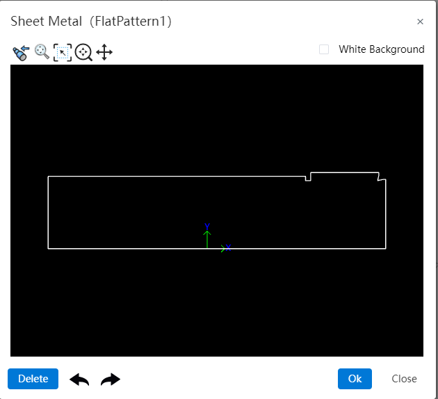
Dialog Box Controls:
Buttons (from left to right): Previous Page, Previous View, Adaptive, Focus on Specific Area, Zoom, Pan, Next Page
Previous Page: Click to switch to the previous page.
Previous View: Click this button to return to the previous view perspective.
Adaptive: Same function as in the viewport interface.
Focus on Specific Area: Same function as in the viewport interface.
Zoom: Click and hold the left mouse button to drag up/down. Dragging upward zooms in, dragging downward zooms out.
Pan: Click and hold the left mouse button to pan.
Next Page: Click to switch to the next page.
White Background: Check this option to change the preview viewport background color to white.
Delete: Select lines in the preview window, then click this button to delete them.
Undo/Redo: Undo or redo deletion operations.