# Hole Table
Supports the generation of hole tables and corresponding location identifiers.
Generation method:
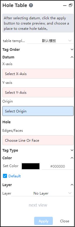
Click [hole table] command to pop up the hole table dialog box.
Select the default table template provided by the system.
Marking order: Expandable option, select XY with radial either way.
Reference point: When positioning the reference location for a hole, point or line elements can be selected. Where a point serves as the origin (X=0,Y=0), lines can be used to define the XY-axes. While the origin can be used independently for positioning, both X and Y-axes must either be selected together or one axis with the origin. The Y-axis is optional.Hole: Select the edge line or face of the hole that you want to add to the hole table.
Mark type: Expandable selection, default is ABC, can be switched to 123 mode.
Next view: Only available during table insertion process, holes from multiple views can be added to one hole table.
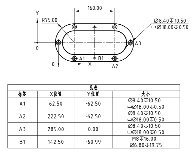
Click the left mouse button and the hole table is generated at the mouse.
Click the left mouse button; a hole table is generated at the cursor position.
Coordinate Direction Editing Method:
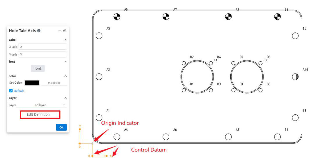
Select the origin indicator to display the "Hole Table Axes" dialog box, where you can configure the text, font, and annotation layer for the X-axis and Y-axis.
Click the "Edit Reference Definition" button in the "Hole Table Axes" dialog box to redefine the coordinate system reference.
Select the indicator and drag the control point to reverse the XY direction, as well as modify the offset distance and direction of the arrow leader from the origin.