Welcome to CrownCAD 2024 R2
CrownCAD 2024 R2 draws the most authentic feedback from users to maximize customer needs. In terms of usability, it is committed to improving customer experience; In terms of functionality, continuously adding commands that customers urgently need can help you quickly complete product design and development work.
Major enhancements:
| Sketches | Optimize sketch line display |
| Add face to sketch features | |
| Add insert picture | |
| Add direct with datum reference | |
| Added "Double click feature to edit associated sketch size" setting | |
| 3D sketches support splitting | |
| Features | Holes: Add custom thread depth, custom hole style, pick up the center point directly |
| Rotary boss/cut supports multiple contours | |
| Scan boss/excise: Supports multiple contours, path supports selection chain | |
| Added the ability to copy surfaces | |
| Assembly | Optimize fit reversal direction |
| Coordinate: support coordinate system, edge line midpoint, center of the circle | |
| Support through the coordinate system transformation | |
| Add triple axis moving parts | |
| Added "Make it stand alone" | |
| Drawing | Adding a half profile |
| Optimized section view: Support to create a projection view as the parent view, local view, support to pick up the center of the circle | |
| Add dimension chain | |
| Add arc length annotations | |
| Optimized dimensional values and standardized display of section lines | |
| Support manual adjustment of center symbol line, center line length | |
| Support marking on the center symbol line | |
| Added ISO and ANSI standard drawing formats | |
| Support for replacing existing drawing sheets | |
| Add insert picture | |
| Support for exporting realistic rendering style drawings | |
| Sheet metal | Base flange supports symmetrical drawing |
| Support custom bending coefficient table | |
| Weldment | Added ISO default style |
| Corner brace supports inherited parameter Settings | |
| Applications | Support for resizing ICONS |
| Select the version to open without entering the document | |
| Support version node renaming | |
| Recycle bin supports sorting by deletion time | |
| Optimize quick determination commands | |
| Optimize the partial scene right-click menu | |
| Add comment unread information | |
| Add "Move" "Delete" permission to share items | |
| Optimize the copy item, increase the location, copy progress | |
| Optimize product navigation | |
| More locations support search items | |
| Support for reading import file thumbnails | |
| Add multiple document open | |
| Optimize task panel | |
| Pickups | Cutaway view state picks up internal elements |
| Translucency supports through-pick | |
| Material Library | Added Search materials |
| Added "AISI304" material |
# Sketch
# 2D sketch
# Optimize sketch line display
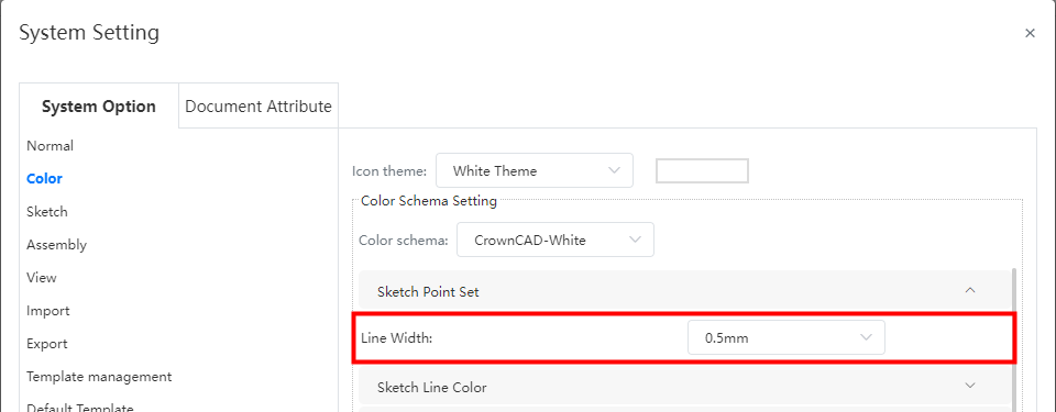
To make it easier to distinguish sketch lines from dimension lines, the default width of sketch lines has been adjusted from 0.25mm to 0.5mm.
This adjustment takes effect only for the color scheme preset by the system and will not affect your custom scheme.
You can make custom adjustments in "System Settings - System Options - Colors - Sketch Drawing Settings -" Sketch Line Width ".
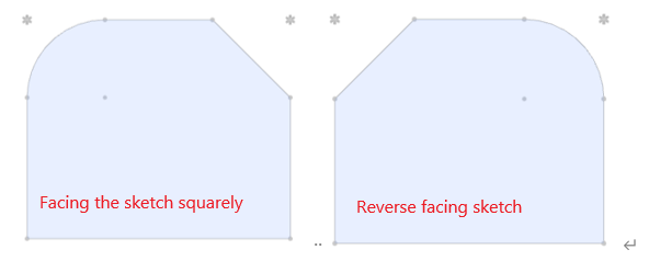
# Look squarely at the sketch features
Right-click the sketch in the viewport or feature panel, add the "Face on"  command to the menu, click this command to face the sketch.
When you have already faced the sketch, click the "Face on" command again to reverse face on the sketch.
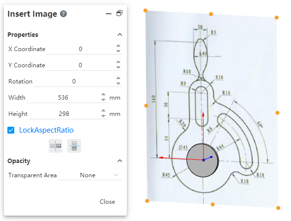
# Insert picture
Insert pictures are supported in 2D sketches for contrast drawing or as a reference.
- Support png,jpg,jpeg,bmp format pictures.
- Only one image can be inserted at a time.
- The inserted picture is not associated with the picture in your project or locally to your computer.
How to insert:
1)Go to 2D sketch.
2)Click the [Insert Picture]  command in the sketch module.
3)Import a picture in the dialog box or select an existing picture in your project.
4)Click Apply. The picture is inserted 1:1 to the sketch origin and automatically enters the editing state.
5)Change the size and position of the picture by modifying the parameters in the dialog box or dragging the picture TAB. The changes take effect immediately.
6)Click the "Close" button to finish inserting the picture.
How to edit:
1)Double click on the picture. A dialog box will pop up with a control label displayed around the picture.
2)Change the size and position of the picture by modifying the dialog box parameters or dragging the picture TAB. The changes take effect immediately.
3)Click the "Close" button to finish editing.
How to delete:
Method 1: Right-click the picture, select "Delete", confirm and delete.
Method 2: Left click on the picture, press delete, confirm and delete.
Transparency:Control the transparent area of the picture.
- None: The picture is not transparent overall.
- From file: For pictures that contain transparent information, such as PNG, the transparent area recorded in the picture appears as transparent.
- Full image: Controls the transparency of the picture as a whole, with 0 being completely opaque and 100 being completely transparent.
# Direct reference with datum level
The reference plane perpendicular to the plane of the sketch is supported in the sketch, and the projection line of the datum plane in the sketch is used as the external reference line.
The datum surface can be used as a reference function: adding constraints, marking dimensions, mirroring axes.
Example:
1)Go to sketch.
2)Pick up the datum in the viewport and hold down ctrl to pick up one more sketch line.
3)In the dialog box that pops up, you can add "Parallel, Vertical, Collinear" constraints for the datum and the selected sketch line.
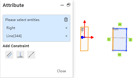
4)For example, add a "parallel" constraint, then the selected datum remains parallel between the projected line in the sketch and the selected sketch line.
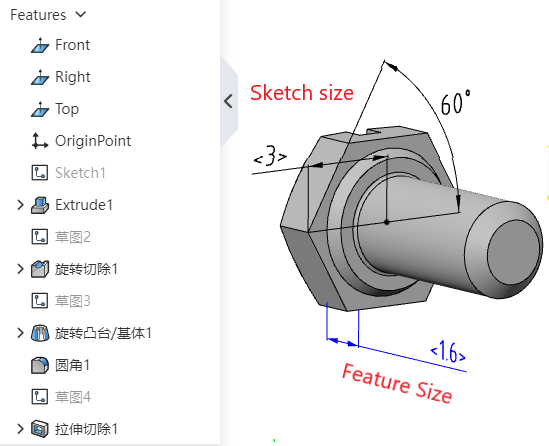
# Double click on the feature to edit the associated sketch size
Double-click the feature in the feature panel to display the feature and its associated sketch size in the viewport. Click the size to modify it directly.
This function is controlled through the "System Settings - System options - Sketch - Double click feature edit size" option.
| The "Double Click Feature Edit Size" option checks the status | Double Click Feature Effect | Double click Sketch effect |
|---|---|---|
| Tick | Show the dimensions of the feature and feature association sketch | Show sketch dimensions, will not enter Edit sketch state |
| Unchecked | Only feature sizes are displayed | Go to Edit sketch state |
Note 1:In the size display state, click anywhere in the viewport or list to turn off the displayed size.
Note 2:This function can only be used outside of the sketch, double clicking on the feature/sketch while editing the sketch will not show the size.
# 3D Sketch
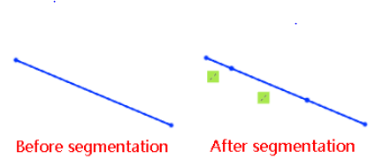
# Split
The "split"  feature is now supported for use in 3D sketches.
Click anywhere on the sketch line, and the line segment breaks into two lines from the click position and automatically adds constraints. The constraint type is the same as the break in the 2D sketch.
Refer to Full User Manual -2D Sketch - Split"" for details。
# Features
# Hole
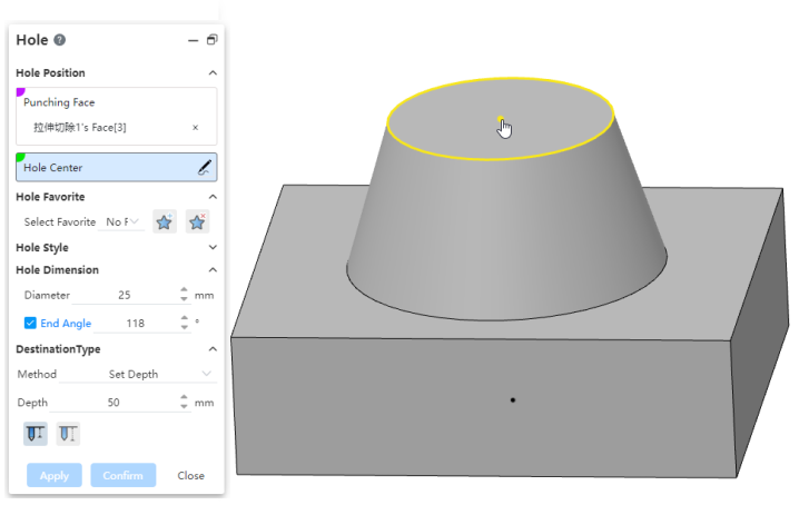
# Custom thread depth
The thread depth of "Thread hole, taper thread hole" in the "hole" command supports customization.
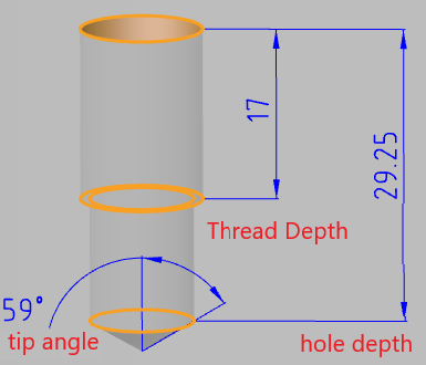
You can customize the thread depth by dragging the Viewport TAB or modifying the parameter of "Thread Depth" in the dialog box.
Dialog box function description:
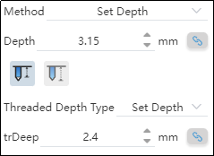
Automatically calculate the depth:Usually, the thread depth and the overall depth of the hole there is a correlation, the system supports the automatic calculation of the other depth according to one depth.
- When the "Automatic depth calculation"
 button behind the depth is pressed, it means that the depth will be automatically adjusted according to the other depth.
 - You can manually click the "Automatically calculate Depth" button as required to switch its pressed state to control whether the system needs to automatically calculate this depth.
Custom parameter display:After a custom parameter is modified, it will be highlighted with a yellow background, indicating that the parameter is not the default parameter of the selected specification.
Restore Default values:Click the "Restore Default Values" button to restore the parameters in the group that are inconsistent with the default values of the selected specifications to the default values of the selected specifications.
# Customize the hole style
You can bookmark custom hole parameters so that they can be called repeatedly in subsequent designs.
Create a collection:
1)Open the parts document and click on the [Hole] command.
2)Select the desired type of hole and customize the modification parameters as needed.
3)Click the "Add or Update Favorites"  button.
4)Enter a name for your collection.
5)Click OK and the creation is complete.
To use Favorites:
1)Open the parts document and click on the [Hole] command.
2)Set the appropriate punch face and hole center point.
3)Select the desired type of hole.
4)Select the collection you want to use.
5)Click OK to create the hole feature using the parameters of the selected collection.
To edit the collection:
1)Open the parts document and click on the [Hole] command.
2)Select the type of hole you want to edit the hole collection and customize the modification parameters as needed.
3)Click the "Add or Update Favorites" button.
4)Select the name of the hole collection you want to edit from the drop-down box. The dialog box will prompt you to update this collection.
5)Click OK, the editing is complete, and the selected hole collection is updated to the new parameters set in step 2.
Note:Editing the favorites does not affect the hole features that have already been created.
To delete a collection:
1)Open the parts document and click on the [Hole] command.
2)Select the hole collection you want to remove.
3)Click the Delete Favorites  button.
4)Select the name of the hole collection you want to edit from the drop down box, and the dialog box will prompt "Will update this collection."
5)Click OK, the editing is complete, and the selected hole collection is updated to the new parameters set in step 2.
Note 1:Deleting a collection does not affect the hole features that have already been created.
Note 2:Hole favorites can also be deleted in system Settings, see "Managing Favorites" for details.
To Manage your favorites:
1)Open the "System Settings - Template Management - Hole Favorites" page.
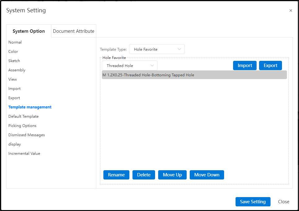
2)Select the type of hole and the specific hole collection you want to manage.
3)You can perform management operations such as "Delete, rename" by clicking buttons on the interface.
Import/Export Favorites:
1)The System Settings - Template Management - Favorites page is displayed.
2)Click the "Export" button, and the hole favorites data file can be downloaded to the local PC through the browser.
3)Click Import, select an existing local data file, and set how to handle the Duplicate hole data file.
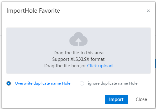
4)Click the "Import" button to complete the import.
Note:Import and export operations affect all types of hole collections.
# Pick up the center points directly
When specifying the center point of the hole, hold the mouse on the edge of the circle for a while, and when the center of the circle is displayed, you can pick up the center as the center point of the hole.
# Rotate the boss/cut out
Rotating the boss/excision supports selecting a sketch containing multiple Outlines, rotating to produce an entity containing multiple unconnected areas.
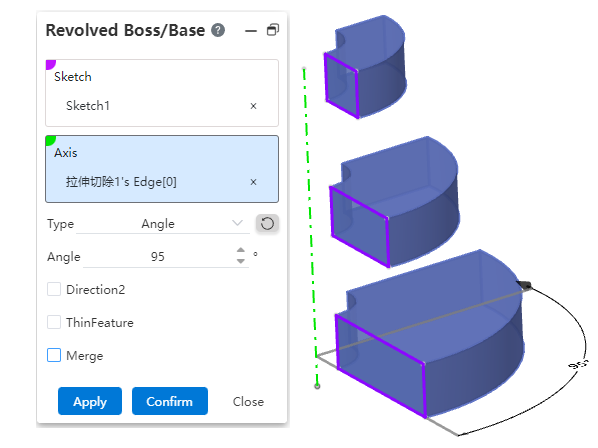
Rotate boss/Excise support select undissolved text for rotation.
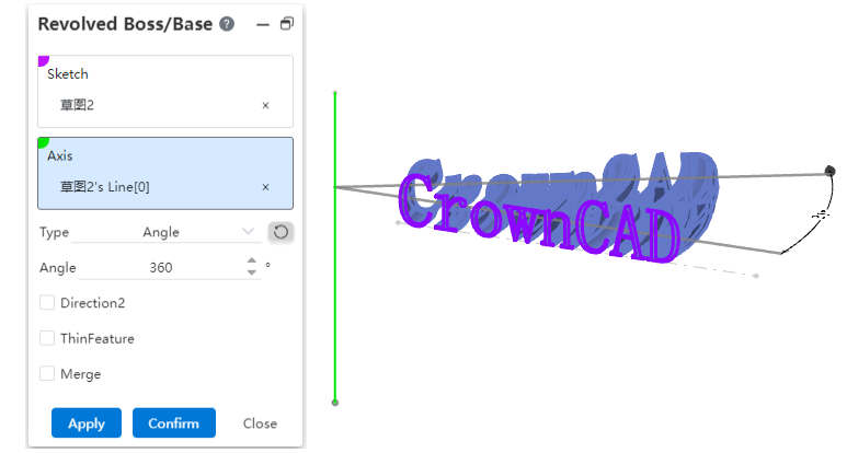
Note:If the outline in the sketch intersects, or the result after rotation intersects, the feature cannot be created.
# Scan the boss/excise
Scanning the boss/excision supports selecting a sketch containing multiple disjointed Outlines and scanning to produce a solid containing multiple disjointed areas.
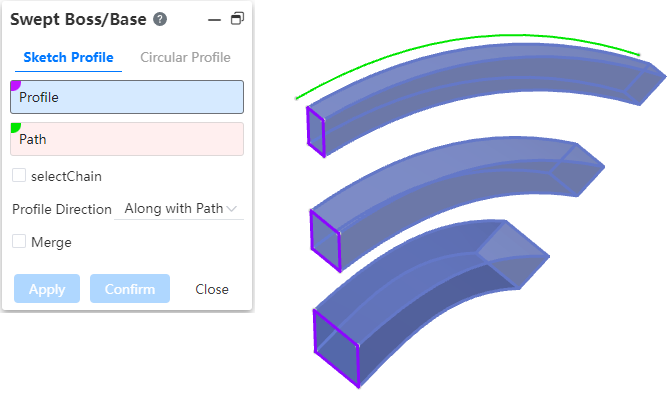
Scan boss/Excision support selects undissolved text for scanning.
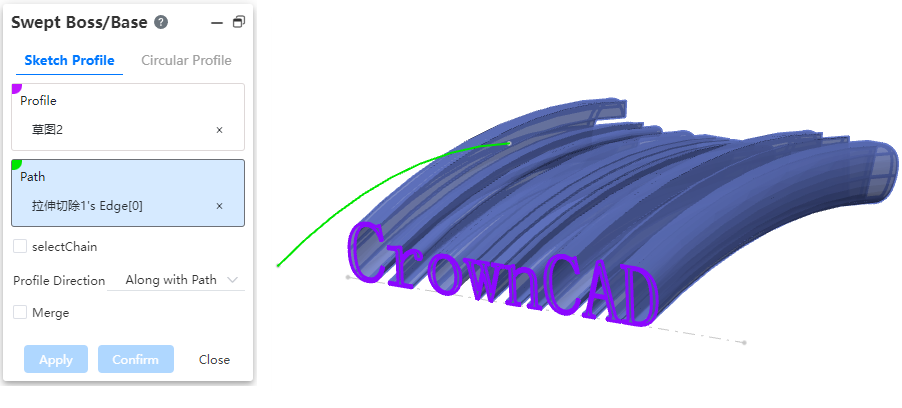
Note:Features cannot be created if the Outlines intersect within the sketch, or if the scan results intersect.
The scan path supports the "select chain" function, check this, the system automatically calculates the line connected with the selected element as the scan path.
Note:Select chain function action elements are only available for lines of the "Sketch non-reference line, spatial curve" type.
# Duplicate surfaces
The surface module supports the "Copy surfaces" command. It can be used in the assembly Topdown environment, which can directly extract the surface of other parts and maintain the correlation relationship.
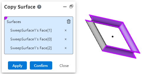
Steps to use:
1)Click the [Copy Surfaces]  command of the surface module.
2)Select the surface you want to copy in the viewport, which can be picked up from a solid or a surface.
3)Click OK/Apply and the selected surface piece is copied.
Note:After copying, the connected pieces will be stitched into a curved surface.
# Assembly
# Mate
Optimize to fit the default orientation, which is now the orientation you want in most scenarios.
Support to pick up the "coordinate system" to add a match.
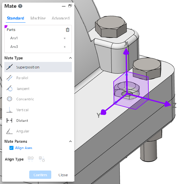
- Pick coordinate system with other elements, coordinate system origin with other elements to cooperate.
- Pick up two coordinate systems and display the "Alignment Axis" option when selecting the "Overlap" type. Check "Align Axes" so that the two coordinate systems coincide exactly.
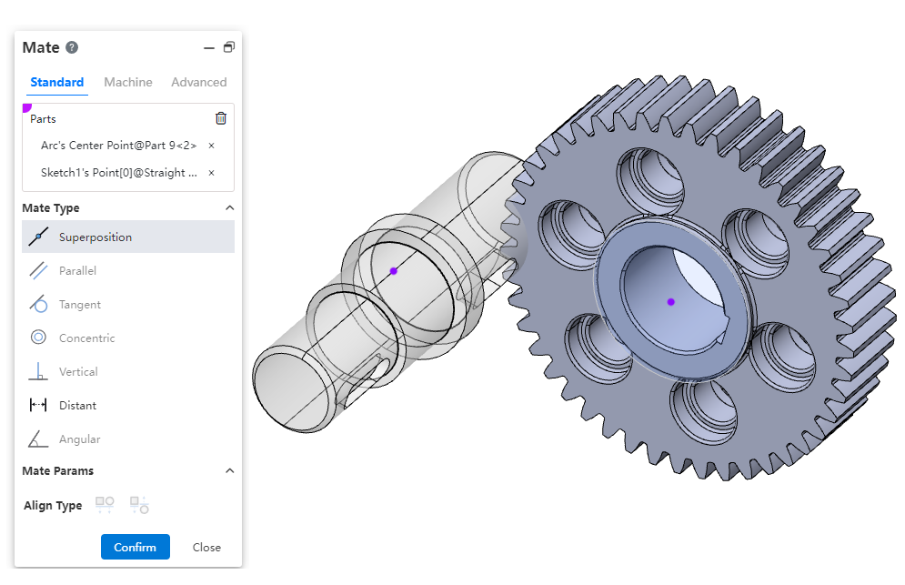
Support picking "midpoint of edge line, center of sketch circle" to add fit.
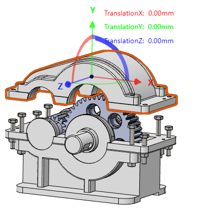
# Transform instance
The Transform instance function supports the "coordinate system" mode.
![]()
Note:You can expand the parts in the feature panel and click the eye button after the reference coordinate system feature to display the coordinate system for picking up in the viewport. Or click the reference coordinate system feature directly in the feature panel to pick up.
# Triple axis moving parts
Supports moving parts by dragging and dropping the triple shaft.
How to use:
1)Right click on the part you want to move in the viewport.
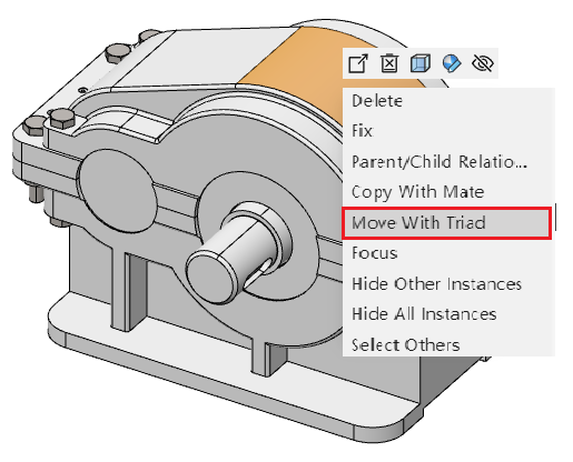
2)Select "Move with Triple Axis" and the triple axis is displayed on the part.
3)Drag and drag the triple axis to move the part.
4)Click on the blank space of the viewport to end the move.
Note:Fixed parts cannot be moved, and there is no "Move by triple axis" option in their right-click menu.
# Make it independent
Supports saving existing parts in the assembly as a new document, and the assembly will reference the newly generated document.
How to use:
1)Right click on the part you want to stand alone in the viewport or feature panel.
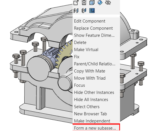
2)Select the "Make it Separate" option.
3)Set the name and location of the new document.
4)The selected part is saved as the new document, and the new document is assembled to replace the original document.
# Drawing
# Section view enhancement
# Half section
Support for creating half section views.

Use the Section view command, switch to the "Half Section" Tab, select the section direction, click in the view to specify the section position, move the mouse and place the view to complete the half section view creation.
# Section view label can be edited font
Click the "Font" button in the Section View dialog box to set the font for the Section view label.
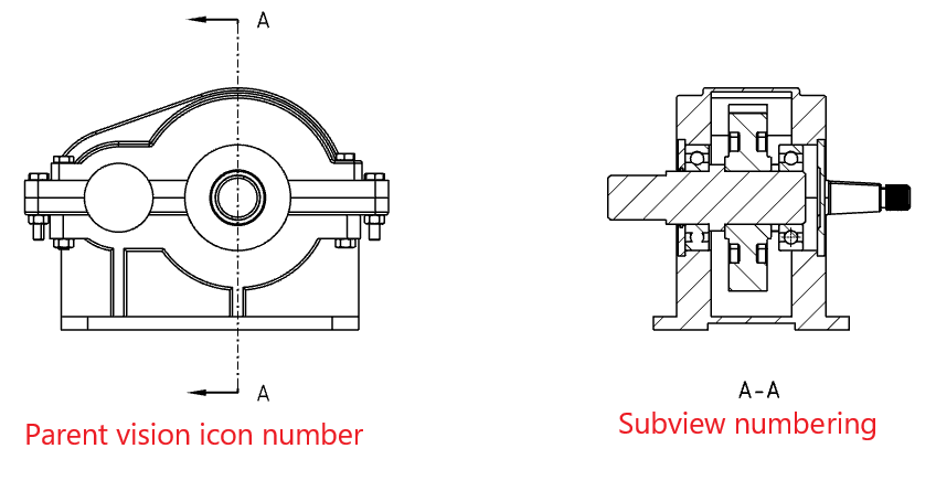
After setting the font, you will be asked if you want to apply it to the subview at the same time. Select OK to change the label font for both the parent view and the subview; Select Cancel and change only the label font for the parent view.
Click the label of the subview directly, and you can set the label font of the subview separately in the pop-up "Comment" dialog box.
# The cut line can pick up the center of the circle
When you create a normal section view specifying a cut line, place the mouse over the edge of the circle and the cut line automatically passes through the center of the circle.
When creating a half cutoff view or adding a step feature to the cut line of a normal view, since you may need to place the pass point on the circular edge (instead of the center), the center will not be captured automatically, but the center will be highlighted so that you can capture the center manually.
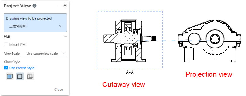
# Projective view
In the projection view, you can select the section view for projection. The projection content is the complete model rather than the model that is cut.
# Local view
# Support section view
Section view can be selected to create a local view, and the projection content is the model after cutting.

# Support to modify the scale
Local view scaling supports selecting custom scaling.
By default, it is twice the size of the parent view. After creating the local view, select the local view. In the "View Scale" of the dialog box, you can customize the scale.
# The name of the local view can be edited in font
Click the "Font" button in the local View dialog box to set the font for the local view label.
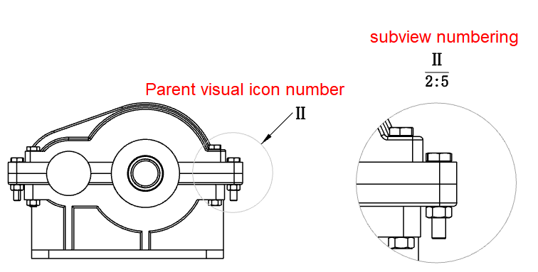
After setting the font, you will be asked if you want to apply it to the subview at the same time. Select OK to change the label font for both the parent view and the subview; Select Cancel and change only the label font for the parent view.
Click the label of the subview directly, and you can set the label font of the subview separately in the pop-up "Comment" dialog box.
# Size
# Dimension chain
Supports the creation of dimension chain annotations.

Creation steps:
1)Click the [Size Chain]  command in the Smart Size drop-down menu.
2)Left click to select the point or line as the dimensioned element of dimension Chain 0 size.
3)Left click again after moving the mouse to place size 0.
4)Select the other elements you want to label to generate the dimension chain label.
5)Click the "Close" button to end the annotation.
Note:Only elements in the same direction can be annotated, not angles.
Add dimension:Right-click the dimension chain that has been created and select "Add to dimension chain" to select other elements to add to the dimension chain.
Delete dimension:Select the dimension of the dimension chain and delete it by the Delete key or right-click menu. Select the non-0 size to delete only the selected size, select the 0 size to delete the entire size chain.
Turn line:When two annotated elements are close to each other, the system automatically turns the size boundary line. Right-click the size chain can manually open/close the turn line, and the size of the open turn line can be adjusted along the direction of the size line.

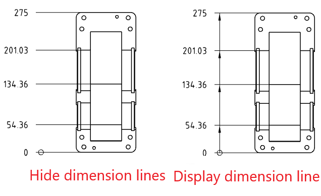
Hide the dimension line:Through the dimension chain dialog box or right-click menu can control whether to display the dimension line in the dimension chain, in order to create a dimension chain that meets the requirements of the drawing standard.
Unalign:The size lines in the size chain line up with each other by default, right-click the size and select "Unalign" so that the selected size can be dragged and dropped independently without maintaining alignment.

# Arc length annotation
Support for creating arc length annotations.

Creation steps:
1)Click the [Label Arc Length]  command in the Smart Size drop-down menu.
2)Click the left button to select the arc edge line to display the arc size preview.
3)Click the left button again after moving the mouse to place the arc dimensions.
4)Continue to select other arcs that you want to label for continuous labeling.
5)Click the "Close" button to end the annotation.
Note:Only arc edges can be annotated.
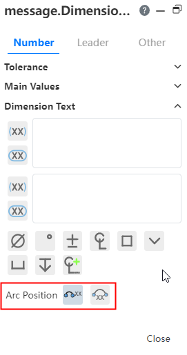
Label style:The size boundary style can be modified as shown in the following figure.
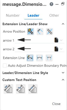
Arc symbol position:The arc length marked arc position and dimension boundary line style can be modified as shown in the following picture.
# Section line optimization
When the dimension value coincides with the profile line, the profile line will break the deflecting dimension value.

# Center symbol line
The center symbol line default out of length can be set in "System Settings - Document Properties - Center Line/Center symbol Line".
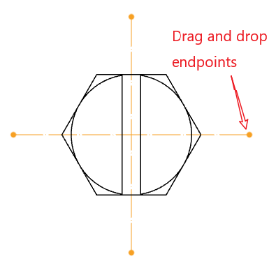
Select the center symbol line that has been created and drag the end point of the center symbol line to modify the length of the center symbol line.
Size, roughness and other annotations support annotation on the center symbol line.
# Center Line
The centerline default overlength can be set in "System Settings - Document Properties - Centerline/Center Symbol Line".
# In-view sketch
When sketching in view, it supports capturing the center of the circle inside the view.
Hold the mouse on the edge of the circle for a while. When the center of the circle is displayed, you can pick up the center.

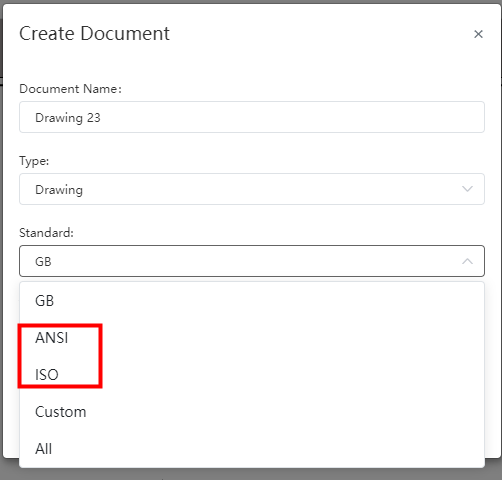
# Standard Drawing Format
New drawings supporting ANSI and ISO standards.
When creating a drawing, select the required standard to invoke the drawing of the corresponding standard.
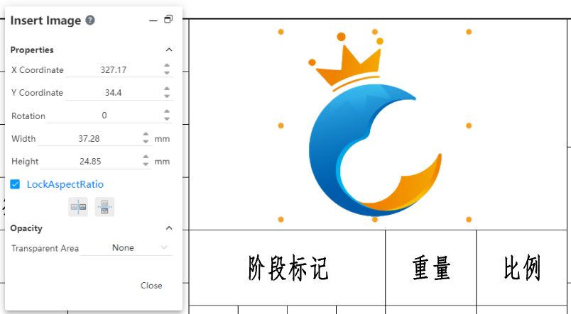
# Insert picture
Insert picture is supported in the engineering drawing.
- Support png,jpg,jpeg,bmp format pictures.
- Only one image can be inserted at a time.
- The inserted picture is not associated with the picture in your project or locally to your computer.
- The picture cannot be inserted into the view, i.e. the picture cannot be inserted while locking the focus view.
How to insert:
1)Click the [Insert Picture] command in the sketch module.
2)Import a picture in the dialog box or select an existing picture in your project.
3)Click Apply and the picture is inserted to the origin in a 1:1 ratio and automatically enters the editing state.
4)Change the size and position of the picture by modifying the dialog box parameters or dragging the picture TAB. The changes take effect immediately.
5)Click the "Close" button to finish inserting the picture.
How to edit:
1)Double click on the picture. A dialog box will pop up with a control label displayed around the picture.
2)Change the size and position of the picture by modifying the dialog box parameters or dragging the picture TAB. The changes take effect immediately.
3)Click the "Close" button to finish editing.
How to delete:
Method 1: Right-click the picture, select "Delete", confirm and delete.
Method 2: Left click on the picture, press delete, confirm and delete.
Transparency:Control the transparent area of the picture.
- None: The picture is not transparent overall.
- From File: For pictures such as PNGS that contain transparent information, display the transparent area recorded in the picture as transparent.
- Full picture: Controls the transparency of the picture as a whole, with 0 being completely opaque and 100 being completely transparent.
# Alternate map
Support replacement maps after the drawing is created.
Replacement method:
1)Right view panel drawing.

2)Click the "Properties" option to bring up the drawing Properties dialog box.
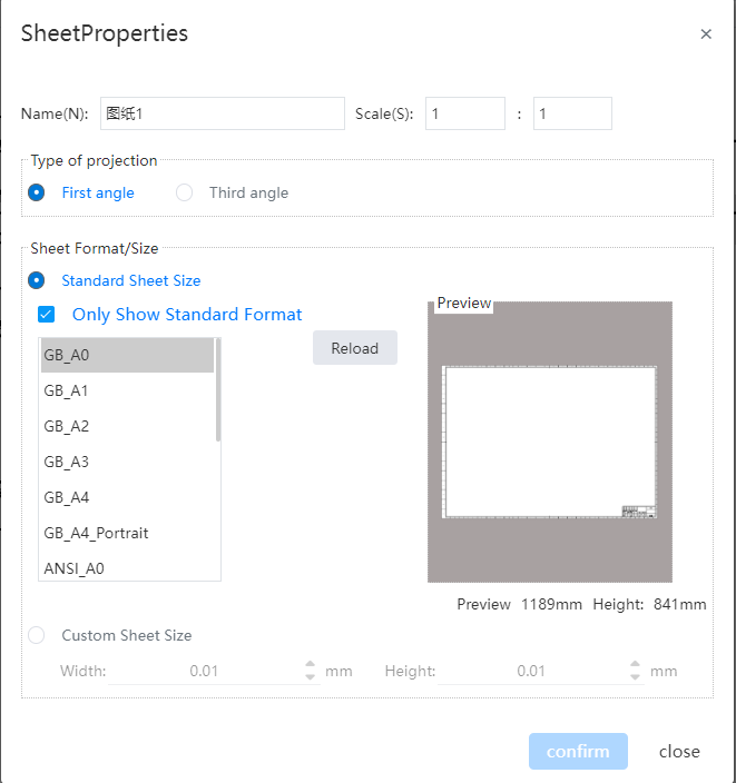
3)Select which drawing format you want to replace to in the dialog box.
4)Click the "Confirm" button to complete the replacement.
Note 1:The contents of the drawing format disappear after replacement, and the contents of non-drawing format such as views and annotations remain unchanged.
Note 2:Select the current drawing format and click "Reinstall" to restore the drawing format content as the default content.
# Export
When exporting a PDF, the view set to coloring style will be exported as coloring style, i.e. the model colors will be displayed.
# Sheet Metal
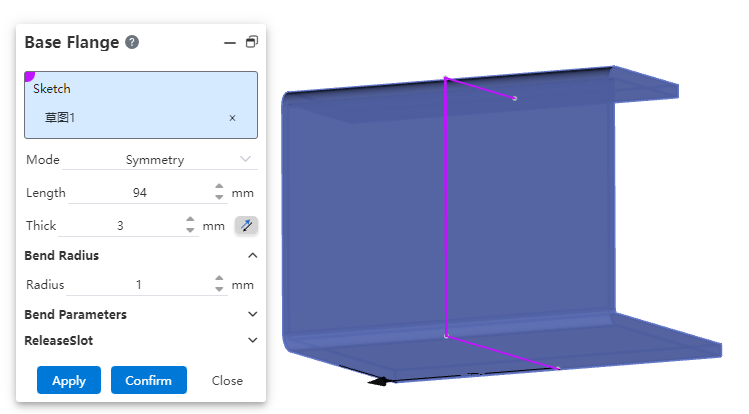
# Base flange
The base flange supports the "bilateral symmetry" mode, and draws symmetrically from the sketch reference to both sides to generate the base flange.
# Table of bending coefficient
Support user-defined bending coefficient table.
How to upload:
1)Click Upload in "System Settings - System Options - Template Management - Bending Coefficient Table", the dialog box will pop up.
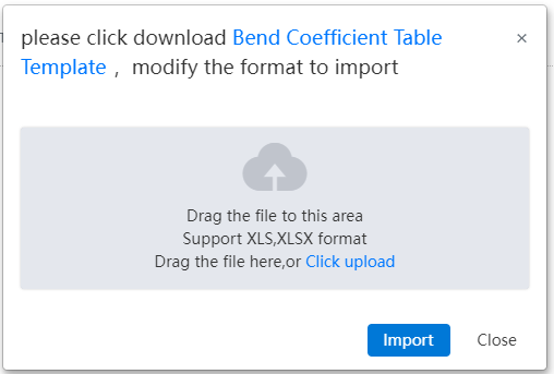
2)Click "Bending Coefficient Table Template" in the dialog box that pops up to download the template.
3)Follow the template format to create the bending coefficient table.
4)Place the bend coefficient table file into the dialog box.
5)Click Import to complete the upload.
Bending factor table contents:
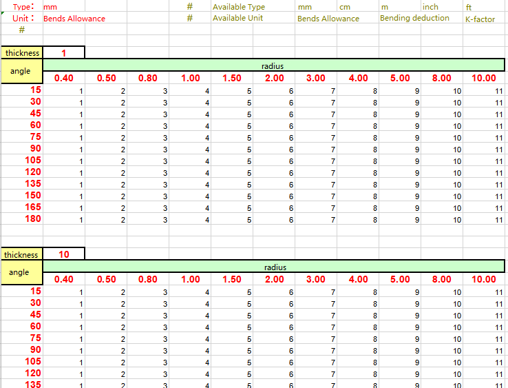
- Unit:Set the unit of the bending coefficient in the current bending coefficient table. The unit can be mm, cm, or meter.
- Type:Set the type of the bending coefficient table. The supported types include bending coefficient, bending deduction, and K-factor.
- Thickness:Set the thickness of sheet metal corresponding to the current bending coefficient table. One table can contain multiple bending coefficient tables of thickness, and the radius values of each bending coefficient table need to be consistent.
- Angle:Set the sheet metal bending Angle. (Different thickness parameter sheet, Angle can be different.)
- Radius:Set the sheet metal bending radius. (The bending radius must be the same for parameter tables of different thicknesses.)
Note 1:A table can contain a table of bending coefficients of multiple thicknesses, separated by blank rows, and the spacing of blank rows cannot exceed 10.
Note 2:Fill in the corresponding bending coefficient in the cell corresponding to the Angle and radius of the bending coefficient table.
Modify the bending coefficient table:
1)In "System Settings - System Options - Template Management - Bend Coefficient Table" select the bend coefficient table you want to modify.
2)Click Download to download the table to your local computer.
3)Modify the form.
4)Re-upload the form, taking care to keep the form name the same.
5)You will be prompted to override the form, click OK to complete the changes.
Note 1:Modifying the form does not affect the features already generated.
Note 2:If you need to update the features to the latest table, edit the features again and re-select the table.
To manage the table of bending factors:
1)In System Settings - System Options - Template Management - Bend Coefficient Table, select the bend coefficient table to be modified.
2)Click buttons such as "Delete, Rename" to manage the bend coefficient table.
# Weldment
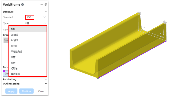
# Structural members
GB standard added H steel type presets.
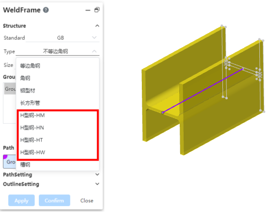
New ISO standard and structure profile type presets under multiple ISO standards.
# Corner strut
The corner brace supports inheriting the parameters used last time, which makes it easy for you to quickly create multiple corner braces with the same parameters.
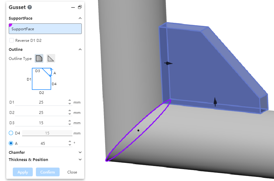
Note:The recorded parameters are temporary, and the historical parameters will be cleared and restored to default values after you refresh the page.
# Apply
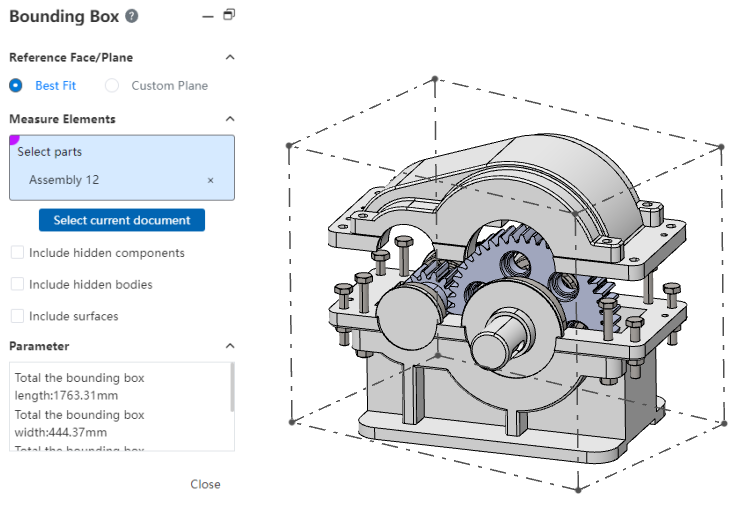
# Bounding Box
Support for measuring the minimum cube area parameters that fully enclose the model.
How to use:
1)Click the [Boundary Box]  command of the evaluation module, and the "Boundary Box" dialog box will pop up.
2)Set the bounding box generation mode "best fit, custom plane".
- Best fit: The direction of the bounding box is automatically adjusted to generate the bounding box with the smallest volume.
- Custom plane: Specify a plane where one face of the bounding box is parallel to this plane to generate a bounding box of minimum volume that meets the condition of parallelism.
3)Click Select Current Document to select the current document, or select the element you want to measure in the Viewport/Features panel.
- Select Current document: Calculate the bounding box of all models in the current document, with options to control whether to include hidden elements/surfaces.
- Select Measurement elements: Manually specify which models to measure and calculate the bounding boxes that surround all the selected models. Surfaces/entities can be picked up in parts and parts can be picked up in assembly.
4)The boundary box is displayed in the viewport, and the parameters of the boundary box are displayed in the dialog box.
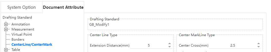
# Document Properties
Engineering drawings support setting the default extension length of the center line, and the setting item is located in "System Settings - Document properties - Center line/center symbol line".
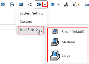
# Resize the icon
Icon size modification is supported, which can be modified through the "System Settings drop-down box".
# Versions and Branches
Select version to open without entering the document:
1)In the document list within the project, right-click the document and select "Version".
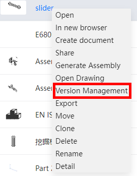
2)Select version in the dialog box that pops up to open it.
Nodes and branches support renaming:
1)Click Version in the document to open the Version and Branch dialog box  .
.
2)Right-click the node or branch you want to rename to bring up the naming dialog box.
3)Enter the name and click "Modify" to finish renaming.
Note 1:The same name is not allowed for different branches.
Note 2:Nodes under the same branch are not allowed to have the same name.
# Recycle Bin
Support sorting by deletion time.
# Quick determination
Optimize the quick determination function for sketches/parts/assemblies/engineering drawings.
Sketch:Use the "Straight Line, Polygon, spline curve, cross curve" command. Right-click while drawing to add [Create, Exit] option in the function list, click "Create" to create elements but not exit the command, click "Exit" to create elements and exit the command.
Parts/Assembly/Drawing:When the mouse is operating in the viewport, you can quickly switch the next pick box or quickly create features.
- For commands that have multiple pick boxes, the mouse
 displays as when the pick completes the contents of one pick box. Right click at this point to switch to the next pick up box.
 - When the required elements of the feature are set and can be created, the mouse
 will display as. Click the right button to create the feature.
# Right-click menu
# Feature right-click
Partial right-click operations can still be performed in the list after entering the sketch in the parts and assembly document.
You can select "Exit Sketch" when entering sketch right click datum in part.

Other options in the right-click menu have the same function as outside the sketch, but the "Edit feature, Delete, rename" function cannot be used.
# Generate an assembly
How to use:
1)In the document list, right click the part or assembly document and click the "Generate Assembly" option.
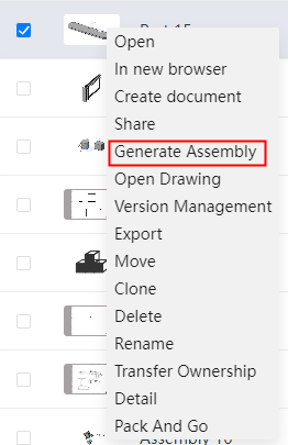
2)Select the template and set the name.
3)Click the Create button to create the assembly and the selected document is automatically inserted into the assembly.
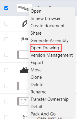
# Open drawings
In the document list, right click the part or assembly document and click the "Open Engineering Drawing" option. The associated engineering drawing of the selected document will automatically open.
# Comments
When you open a document with unread comments, the comment icon  in the upper right corner shows the number of unread messages.
When there is an unread message, opening the comment will automatically display the position of the first unread message, and the unread message will automatically update after reading, click again to jump to the second message, and so on until the message is all read.
# Share
Share When selecting editing permissions, add the "Move, Delete" permission control items for documents in the project. By default, two items are selected. Cannot be selected when read-only permission is selected.
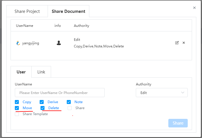
Moving or deleting corresponds to documents and folders in the project. When sharing a folder, the items in the folder cannot be moved/deleted.
# Copy Project
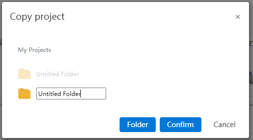
Copy items support the choice of destination location, support for fast new folders.
The progress bar is displayed during the copying process. No operation can be performed on the project at this time.
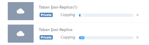
Click the cancel button after the progress bar to stop the replication, and the progress bar will become normal and available in the project.
Note:After canceling the replication, you can not continue to copy, you need to copy again.
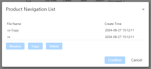
# Product Navigation
- Navigation list supports delete, rename, and copy functions.
If you click Product Navigation in a document, a new TAB is created to open the product navigation page, avoiding overwriting the currently opened document
Click Product Navigation in the Assembly document to automatically open Existing Files and locate the project where the assembly is located.
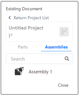
- Reference the existing assembly structure, adjust the structure, the output document can choose how to deal with the existing parts.
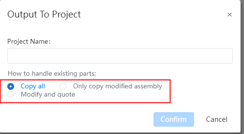
- Copy all: Copy all the existing parts to the new project, reference the copied new document.
- Copy only the modified assembly: Copy the modified existing assembly into the new project, and reference the source document for the other parts.
- Modify and reference the source document: Without copying, modify and reference the source document. Select this method, when the top-level assembly is an existing assembly, you do not need to give the project name, directly in the assembly original project to create a new document and modify the existing assembly.
- Other optimizations
- Hold down ctrl and drag parts to copy to another location.
- Support to read user-defined assembly, parts, engineering drawing templates.
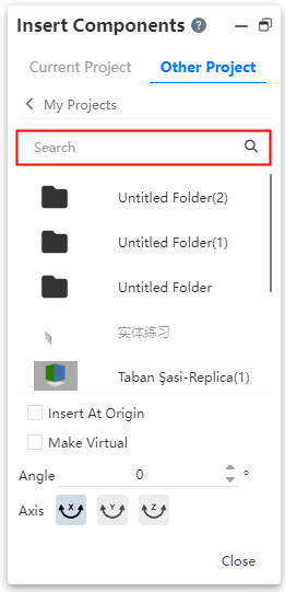
# Project Search
Add project search in dialogs such as Assembly insert parts, product navigation existing files, engineering drawing view palette, etc.
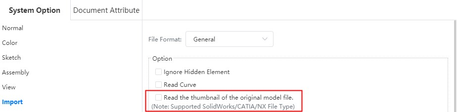
# Display thumbnails
Support for reading thumbnails of documents in SolidWorks\NX\CATIA format, this can be enabled by checking "Show Thumbnails" in "System Settings - System Options - Import - Options".
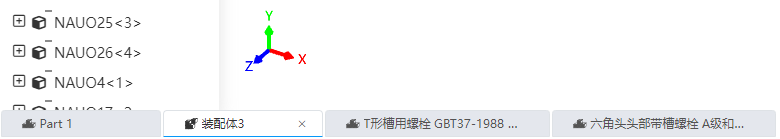
# Multi-document Open
Display all open documents in the current project under one TAB, switching documents at the bottom of the page.
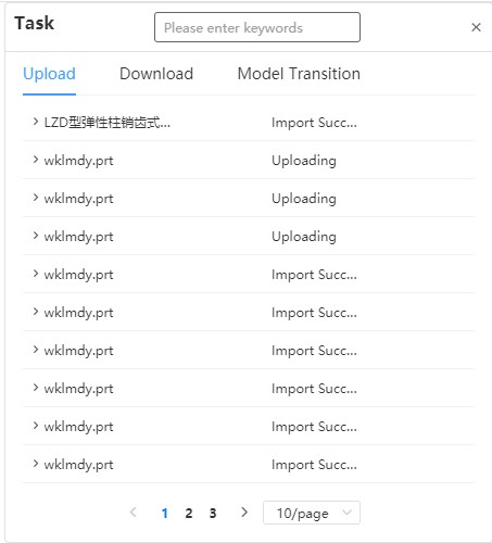
# Task Panel
Task panel adds dividers and paging Settings.
# Picks Up
In the sectioned view state, the elements inside the parts that were originally shielded can be picked up, and the faces that have been cut and hidden will not be picked up.
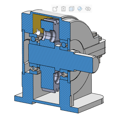
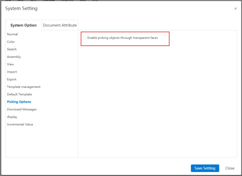
Check the option "Enable through Transparent surface selection" in "System Settings - System Options - Selection". You can pick up other non-translucent faces, edges, vertices and other elements through translucent faces.
# Material Library
Material library supports search.
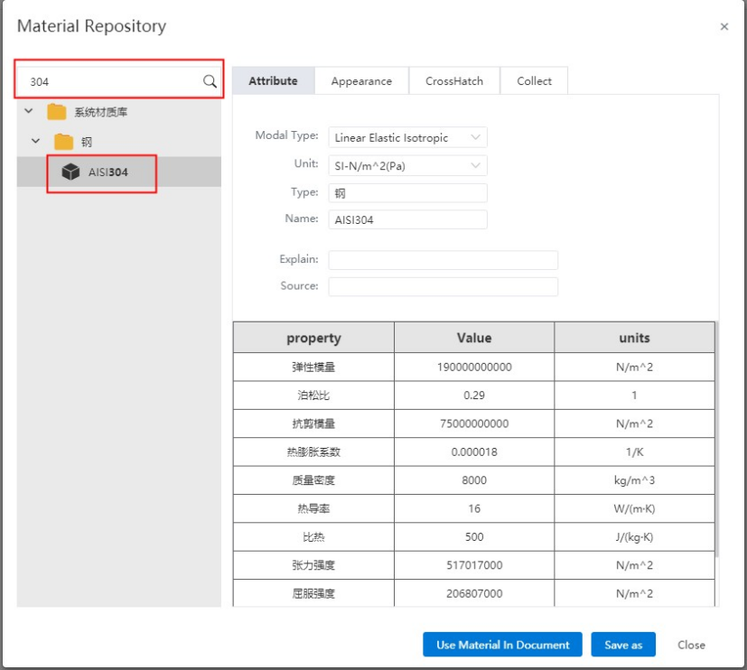
System material library added "steel" category, and provide "AISI304" material, that is, "stainless steel material 06Cr19Ni10".