# Welcome to CrownCAD 2024 R3
CrownCAD 2024 R3 draws on the most authentic feedback from users to maximize customer needs. In terms of ease of use, it is committed to improving customer experience; In terms of functionality, continuously adding commands that customers urgently need can help you quickly complete product design and development work.
Major enhancements:
| Sketches | New dimension chain, benchmark dimensioning command. |
| New 3-point center rectangle drawing command. | |
| Size: New set as driven/reference size function. | |
| Rounded/chamfered: New box selected vertices to create. | |
| Equation curve: New parabola in the curve library. | |
| Features | New Insert Geometry command. |
| Rounding: Added face rounding type. | |
| Hole: Added the function of punching holes on the pickup surface. | |
| Direct body: cuboid and cylinder support to change the dimension direction, support the input point coordinate control entity generation position. | |
| Reference line: Add operation type options. | |
| Decorative thread line: Support more edge styles, support multiple selection of edge lines. | |
| Assemble | New ability to create new subassemblies, change existing component levels. |
| Added the ability to remove parts from subassemblies. | |
| Advanced Fit: Added symmetrical, contour-centered fit types. | |
| Mirror: Added directional parts option, can customize name new document. | |
| Explosion View: Added animation explosion control and export video. | |
| Edit parts: Sheet metal modules are supported, and external references are supported for more commands. | |
| Copy as you go: Multiple parts are supported. | |
| Drawing | New Line line command to set line lines for model projection lines. |
| Added the base size command. | |
| Added automatic size alignment. | |
| New magnetic force line command to facilitate part serial number typesetting. | |
| Added a group of part serial number commands. | |
| New hole table, bending coefficient table command. | |
| New automatic boundary command, can customize the drawing area division and automatically generate picture frame. | |
| New custom drawing size function. | |
| Newly added drawing function, a single engineering drawing document supports multiple drawings. | |
| New import DWG as engineering drawing template function. | |
| Section view: Support split in split. | |
| Local view: Supports custom contours. | |
| Flat Type view: Supports clipping using the Clipping view command. | |
| Auxiliary view: Label support to modify the content, font. | |
| Size: New sleeve tolerance type, support to set reference/review size, support more circle/arc size lead style, size annotation interactive optimization. | |
| Center symbol line: Support for marking straight notch, support for automatic insertion of select view, support for generating connecting lines between center symbol lines. | |
| Table: Added the function of saving table template, added the function of adjusting row height and column width. | |
| Application: Added undo, view alignment, multiple selection delete, box selection and other application functions. | |
| Sheet metal | Base flange: Base flange parameters are used as the default sheet metal parameters. |
| Stamping: Added support for picking up entities with rounded corners for stamping. | |
| Molding: Create rib support for multiple selection lines. | |
| Piping | Piping module added. |
| Structural simulation | Added torque, pressure type of external load. |
| New rigid contact function to create associations between entities. | |
| External loads-forces, boundary constraints: Support added at edges and vertices. | |
| Report generation: More content is added to the report, and customization is supported. | |
| Applications | New selection filter feature. |
| Feature panel: New screening function in Part feature panel. | |
| View/Render | New custom textures feature for adding textures to faces. |
| Added scenery function for modifying viewport background. | |
| Added light source function to control the model lighting effect. | |
| Added render style function. | |
| New addition of viewport function, used to divide viewport into multiple areas. | |
| Set appearance: Add more appearance levels, add advanced appearance parameters. |
# Sketch
# Dimensions
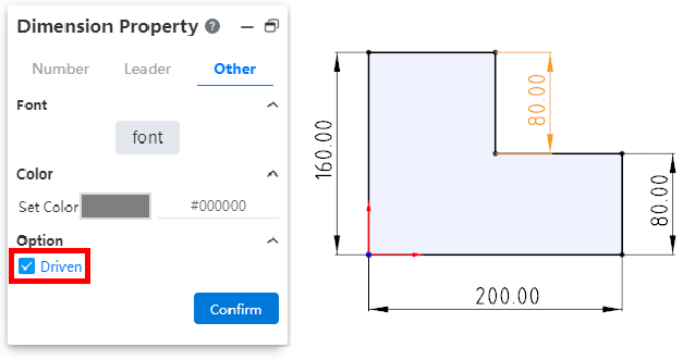
# Driven/reference size
You can create a driven size that only shows the size value but does not drive the model, with no constraint effect.
- To create the driven size:
- Method 1:In "System Settings - System Options - Sketch" select the overdefined size "Default is driven", the sketch will default to generate the driven size when the constraint size is added.
- Method 2:Select the driver size that has been marked, right-click and select "driven size", and click to change the size to driven size.
- Method 3:Select the size that has been marked, check "driven" in the "Other" item in the property panel, and the size will be changed into the driven size after confirmation.
- The slave size is switched to the driver size:
- Method 1:Select the driven size, right-click and select "Drive size", click to change the size to drive size.
- Method 2:Select the size that has been marked, uncheck "driven" in the "Other" item in the property panel, and the size will be changed to the driver size after confirmation.
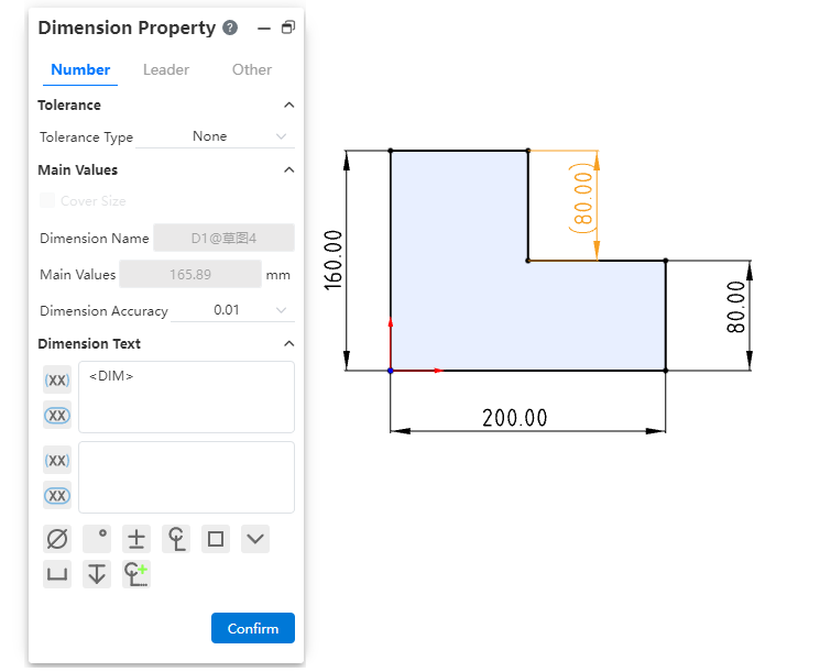
- The driven size is displayed in gray by default, and the color can be modified by "System Settings - System options - Color - Size - Color of the driven size constraint".
- The driven size value is not modifiable and is automatically updated as the relevant constraints and drive size are modified.
- Reference size:In order to better express the size used as a reference in the design, it can be identified by adding () to the size property box.
# Dimension Chain
Support for creating dimension chain annotations.
Creation steps:
1) Click the Size Chain command in the Size Constraints drop-down menu.
2) Left click to select the point or line as the dimensioned element of dimension chain 0 size.
3) Left click again after moving the mouse to place size 0.
4) Select the other elements you want to label to generate the dimension chain label.
5) Click the "Close" button to end the annotation.
Note 1:The driven/drive size can be set, and the drive size can be modified.
Note 2:See Engineering Drawing - Dimension Chain for other functions.其他功能详见
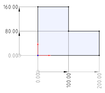
# Benchmark dimensions
Support for creating benchmark dimensioning.
How to create:
Click the Base Size command in the Size Constraints drop-down box
Picks up the elements to be annotated in turn.
The first element is the base element, and the dimensions between subsequent elements and the first element are automatically labeled.
Press Esc to end the annotation.
Note 1:The driven/drive size can be set, and the drive size can be modified.
Note 2:See Engineering Drawing - Reference Size for other functions.其他功能详见
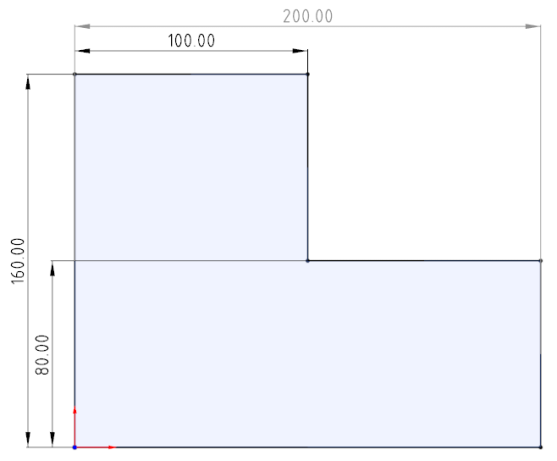
# 3 Point center rectangle
New 3-point center rectangle command to draw slanted center rectangles.
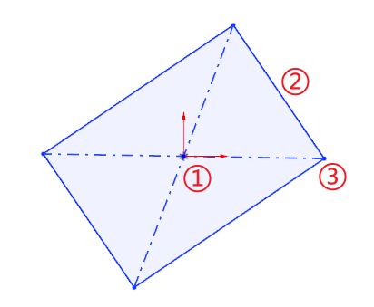
Drawing steps:
Determine the center of the rectangle by clicking the first point in the viewport as the center point.
Drag the mouse and click the second point in the viewport as the middle point of the edge line to determine the length and tilt Angle of the rectangle.
Drag the mouse to make the third point in the viewport the rectangle vertex to create the rectangle.
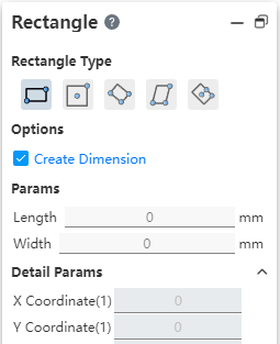
Parameter description:
| Categories | Name | Instructions |
| Parameters | Length Width | The length and width of the rectangle |
| The length and width of the rectangle | Center point XY | Coordinate value of the point at the first mouse click in the viewport |
| Coordinate 1 | Center point coordinates | |
| Coordinate 2 | Second point (midpoint of the line) coordinates | |
| Coordinate 3 - Coordinate 4 | See the coordinates of the third point in the mouth and another point on the same side of it (along the direction of the line formed by the center point and the midpoint) | |
| Detailed parameters(after drawing) | Center point XY | Coordinate value of the point at the first mouse click in the viewport |
| Coordinate 1-4 | 4 point coordinates of the rectangle |
# Spline curve
Spline curves add constraints through point support so that you can more precisely control the shape of the spline curve.
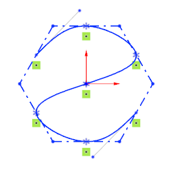
Create a curve:Draw a spline curve, capture other sketch points when left click, will automatically add coincidence constraints.
Modify the curve:Select the passing point of the spline curve, you can directly modify its coordinates in the dialog box, or add constraints.
# Point Coordinates
Points in the sketch that support input coordinates can now be entered into formulas or variables.
Note 1:Coordinate values Input variables only record the current variable value and do not maintain an association with the variable.
Note 2:Only variables of type "numeric" are supported.
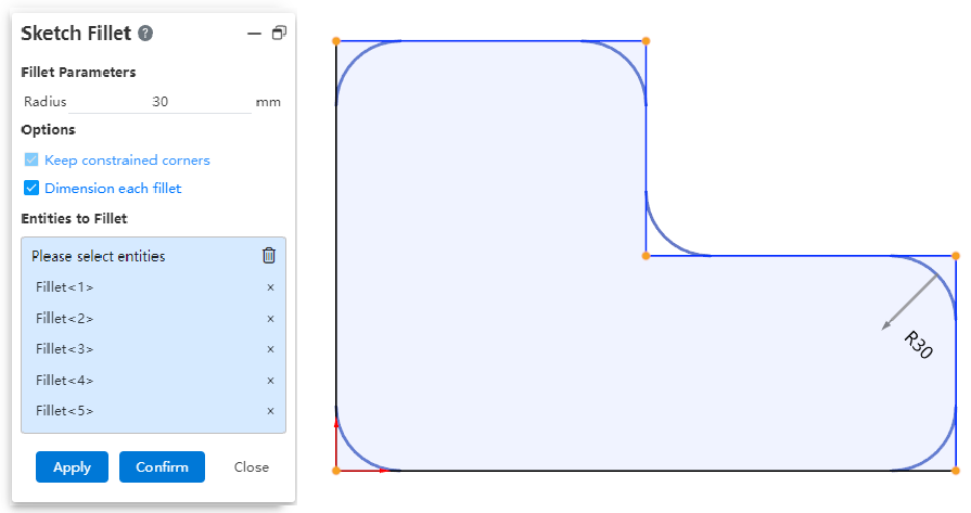
# Rounded/chamfered corners
Both the rounded and chamfered commands now support box pick picking vertices.
# Parabola
New parabola in the Equation Curve library for quick parabola creation.
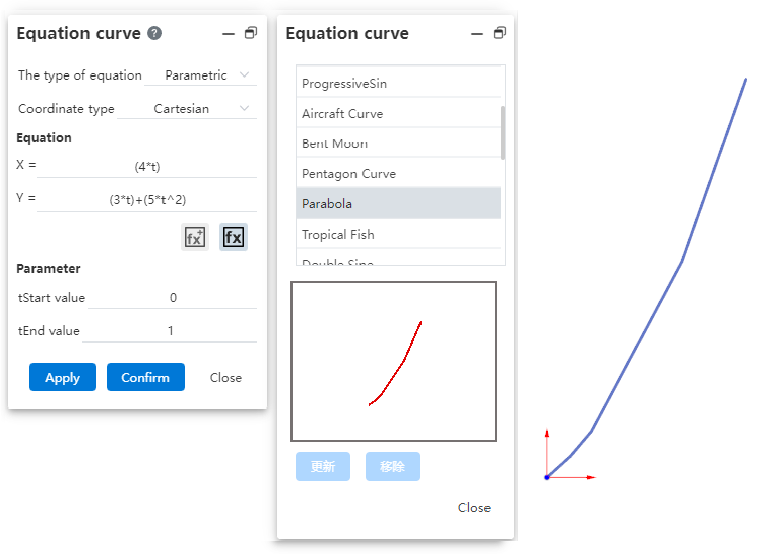
Note:You need to select "Parametric" for the equation type.
# Parts and Features
# Entity
# Hole
Add point punch holes on the pickup surface.
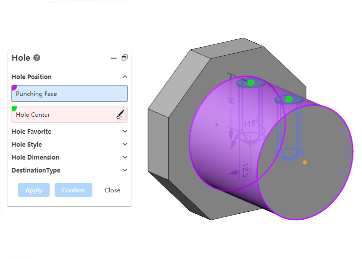
After selecting the punch face, click the left button directly on the punch face to pick up the point on the face.
Expanding the surface point in the dialog box can modify its UV parameters and change the position of the surface point.
# Direct Body
Cylinder, cuboid command support to change the dimension direction, reverse stretching.
Support input point coordinate control entity generation position.
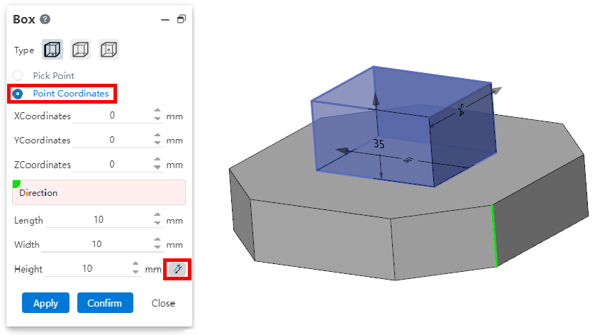
Note: Coordinate value input variable only records the current variable value, and the variable does not maintain association.
# Curved Surface
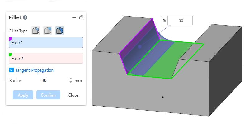
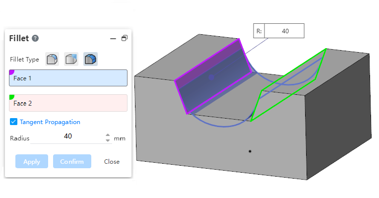
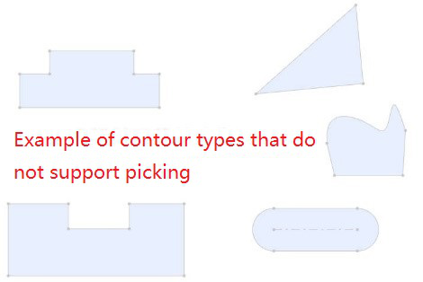
# Face rounded corners
Added face rounding function for creating rounded corners between two groups of faces that are adjacent, non-adjacent, and not contiguous.
Example:
Adjacent faces:
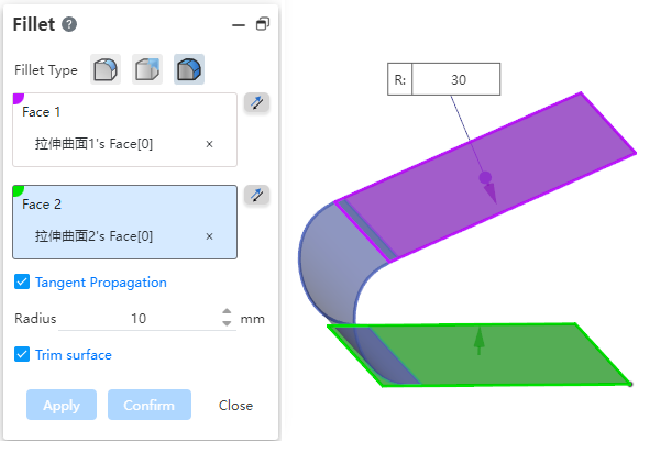
Non-adjacent faces:
Two discontinuous surfaces:
Picking surface requirements:
Only the solid/curved surface can be picked up, not the datum surface.
Surfaces 1 and 2 should be both solid surfaces or surfaces and cannot be mixed for picking.
Face 1 and face 2 of the solid surface can only be selected to belong to the same entity, face 1 and face 2 of the surface can be selected to belong to different surfaces.
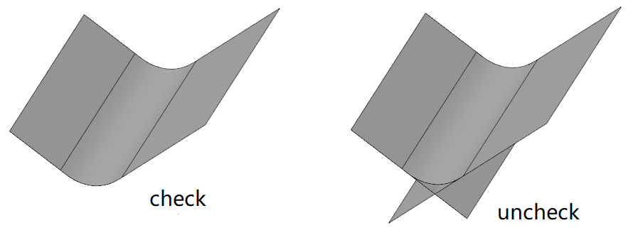
Reverse:
- Displays the reverse button when picking up the surface, which is used to set the orientation of the rounded corners relative to the group of faces.
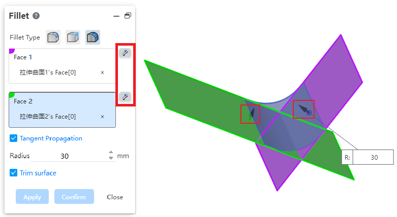
- As shown in the picture above, two face groups intersect, and all 4 directions can generate rounded corners, click the reverse button in the dialog box, or double-click the arrow direction in the view mouth to control the position of the generated rounded corners.
Tangential extension:Controls whether to automatically generate a rounded corner at an unselected tangent plane.
Radius:Controls the radius of the rounded corners. For rounded corners that are not adjacent to each other, the rounded radius should be guaranteed to exceed the boundary before it can be repaired to generate rounded corners.
Clipping surfaces:Available when only surfaces are selected. When checked, the selected surface is cropped and merged with the generated rounded surface into the same surface. When unchecked, the selected surface is left unchanged and an additional independent rounded surface is generated.
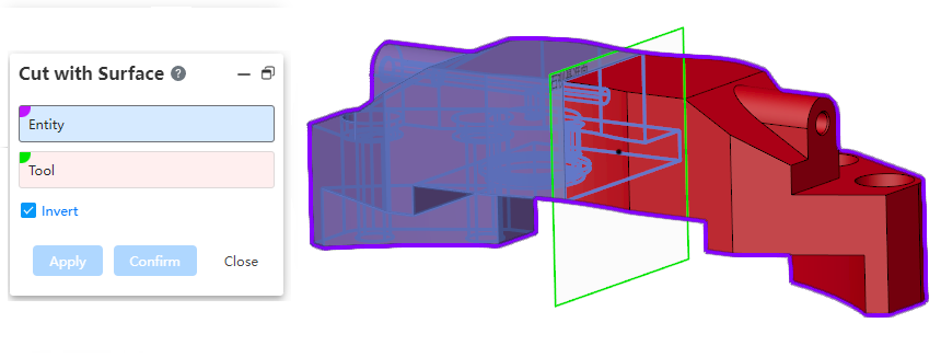
# Using a surface Cut
Support the choice of datum as the cutting tool.
Create curve:Draw a spline curve, and add a revolving beam automatically when you single-click the left mouse button while capturing other drawing points.
Modify curve:Select the through point of the spline curve, you can directly modify its coordinates in the dialog box or add constraints.
# Reference geometry
# Reference line
Add the action type option where you can specify what elements to pick up to generate a baseline.
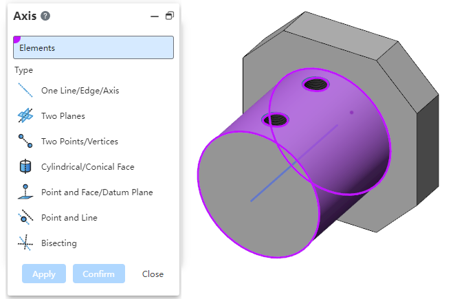
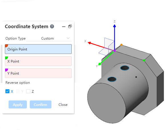
# Coordinate System
The "three-point, three-plane, dynamic, Current view" operation type of the coordinate system command supports reverse, and can be set to reverse one or two directions.
# Insert geometry
New Insert Geometry command to insert geometry from other documents into parts.
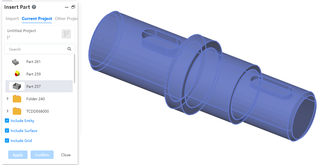
- How to do it:
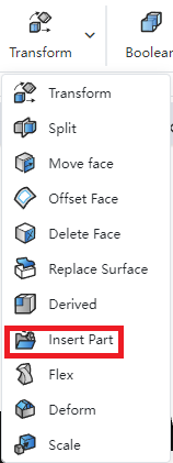
1) In the Parts document, click the Insert Geometry command in the Transform command drop-down menu.
2) Select the geometry document and the type of geometry you want to insert.
3) Click OK.
2 The inserted geometry is not associated with the source file model. Modifying the source file model does not affect the geometry that has been inserted.
3 Support for uploading or selecting existing documents in a project.
Uploading documents consumes the number of uploads.
Only part documents are supported, other documents such as engineering drawings cannot be selected.
Insert only geometry that is in the display state.
4 Support for selecting insert solid/surface/mesh.
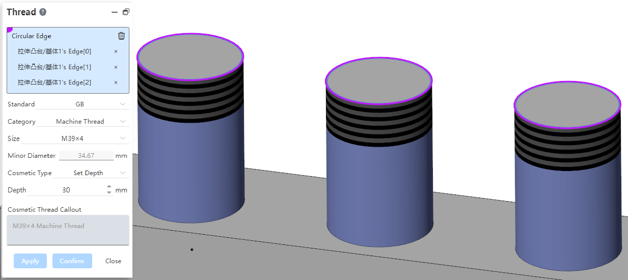
# Decorative threaded lines
Support the selection of non-round edges to create decorative thread lines.
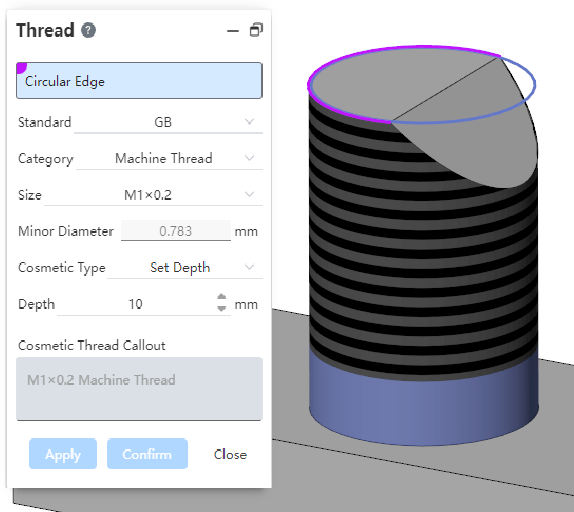
Support the hole edging lines on the cylinder.
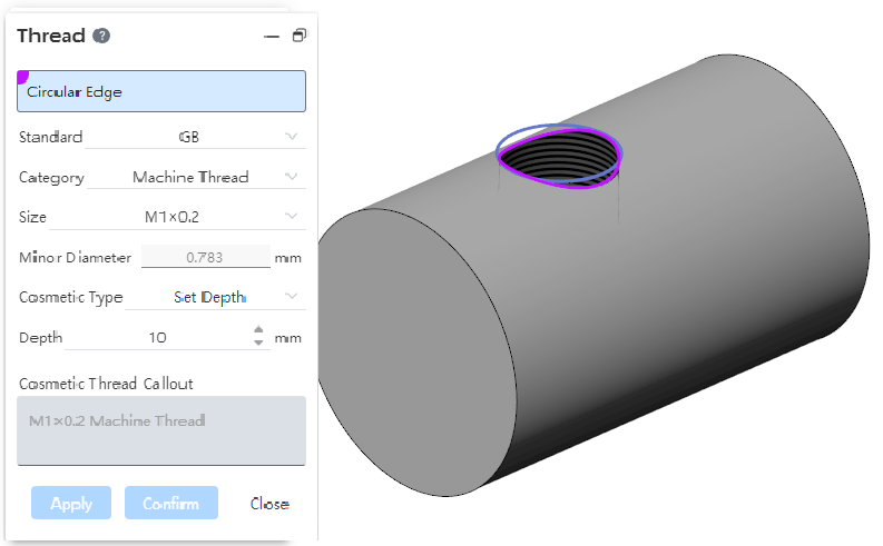
Supports multiple selection edges to create multiple decorative threads at a time.
You can only select multiple edges that are also columns or cones, and can not mix them.
When multiple cylindrical edges are selected, only the edges of the same diameter can be selected.
Each edge line generates a decorative threaded line feature that can be edited separately.
# Assembly
# Advanced Mate
# Symmetry
New symmetric fit type in Advanced fit, so that two solid elements are symmetrical with respect to the datum or plane.
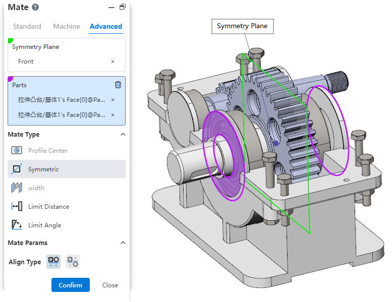
- How to use:Click Match, switch to advanced match, match type select [symmetry].
- Symmetry plane:Select a plane or datum plane.
- Parts:Pick up two elements belonging to different parts to fit together.
- Alignment type: Controls the relative orientation of two elements, including alignment in the same direction and alignment in the opposite direction.
# Center of Outline
New Outline Center Fit type in Advanced Fit aligns the geometric outline center and completely defines the part.
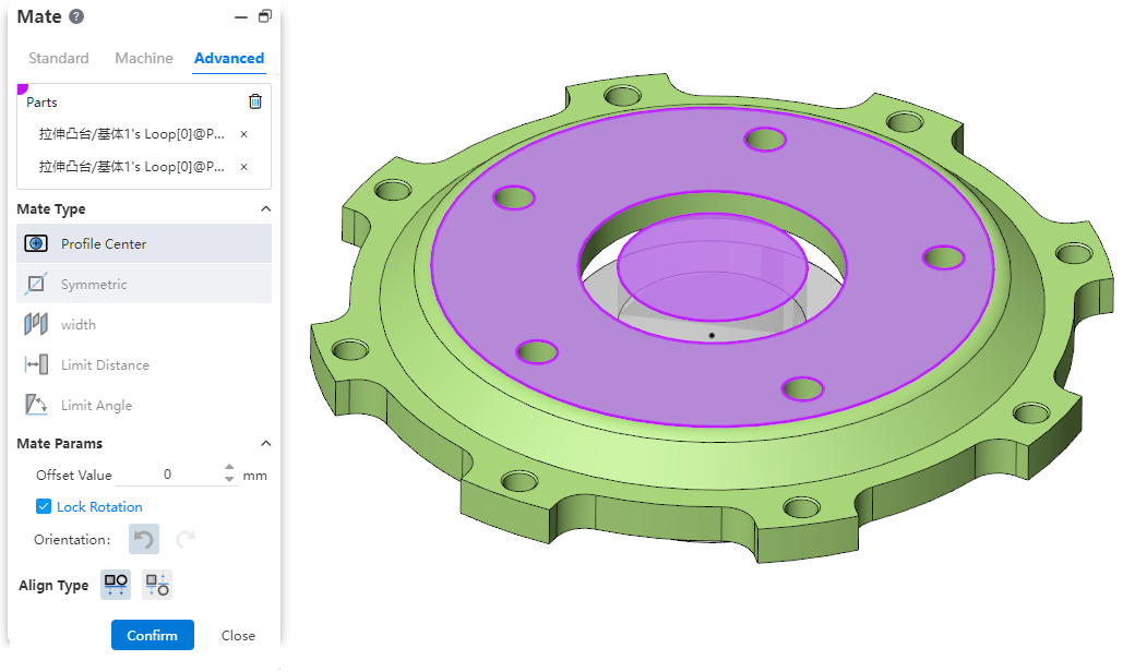
Parts:Pick up sketch lines, edges, or solid surfaces of the two entities to fit.
Element type: Closed loop sketch outline, solid edge line, solid face
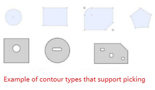
Contour type: full circle, rectangle, regular polygon, rectangle can be chamfered or rounded, face contour can contain incisions
When picking up solid edges, calculate the center of the contour based on the face on which the edges are located
Fit parameters:Offset distance, lock rotation, direction.
Offset distance: Set the offset distance of the center of the two Outlines.
Lock rotation: Select this option when selecting two circular contours to lock the rotation of the part.
Orientation: Use this feature to change the orientation of the part when selecting two non-circular Outlines.
Alignment Type:Controls the relative orientation of two elements, including the same alignment and reverse alignment.
Fit effect:After adding a fit, the contour centers of the two parts coincide, and the constraint state generates different fit effects according to different contour types and options.
When the circular outline is included, if "lock rotation" is checked, it will be completely constrained, and if it is not checked, it can be rotated around the center of the outline.
When circular contours are not included, the parts are fully bound.
# Edit parts
- Support sheet metal functions when editing parts.
- When editing parts, add support for external references in sketches and features:
| Sketches | Array: Directions, points |
| Metaoperation: point | |
| Mirror: Mirror axis | |
| Transform borders: All solid elements | |
| Cross curves: Faces | |
| Features | Transformation: direction, axis, coordinate system |
| Datum plane/line/point: point, line, plane | |
| Coordinate system: point, line, surface, coordinate system | |
| Curves | Three dimensional curves: points |
| Projection curve: Direction | |
| Spiral curve: sketching datum | |
| Curved surface | Rotary surface: Shape to the end of the surface |
| Crop the surface: Tool | |
| Offset surface: Face | |
| Extended/straight grain surface: direction | |
| Array/Base/Mirror: The value is the same as in the feature |
# Mirror
Added part orientation options, select the desired mirror orientation by looking at the preview when switching options.
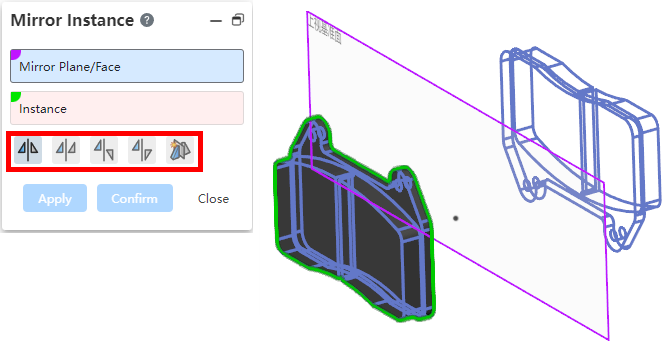
Use the "Generate new document for opposite orientation" option and click OK to customize the name of the new document.
# Generate a new subassembly
New Create a new subassembly function to place an existing part in a new subassembly, lowering the level of that part in the assembly.

Usage:Select one or more parts belonging to the same level in the assembly document, right-click [Generate new sub-assembly] option, set in the pop-up dialog box and click OK.
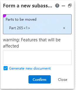
Parameter description:
Parts to be moved: Parts can be picked up or removed.
Warning: Parts that have been array, mirror, stretch cut will have their corresponding features removed, but will not be removed if they are just referring to part elements for direction, generating benchmarks, etc.
Generate new document: Check this item to generate a new assembly document in the same path as the final assembly; Do not check this, only the sub-assembly is displayed in the assembly, there is no document in the list, can not edit the jump.
Function Description:
Under Topdown, this function is not supported when editing sub-assembly.
When selecting the subpart operation of the subassembly, completing the operation directly in the subassembly does not need to enter the Topdown state.
When two parts have a fit, but only one of the parts is moved, the fit remains in the top assembly; When the two parts are matched and moved at the same time, the fit will be moved to the sub-assembly; When multiple parts move to cause coordination conflict, coordination red, wrong coordination can be edited and modified.
Note:This operation does not support cancellation.
# Remove parts
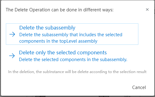
Remove sub-assembly parts from the final assembly:Right-click the parts in the sub-assembly in the final assembly document to delete the parts. You can choose to delete the sub-assembly or delete the parts from the sub-assembly.
Multiple selection deletion optimization:When multiple selection parts are deleted, you can select the specific deletion method.

Button function description:
Yes: When deleting a single part, click to complete the deletion and close the prompt box. When selecting multiple parts, click to display the information of the next deleted item, and so on until all are deleted.
All Yes: This function is available when multiple selection is available, delete all and close the prompt box after clicking.
No: When deleting a single part, click to cancel the deletion and close the prompt box. When deleting multiple parts, click to display the information of the next deleted item, and so on until the end of the option.
Cancel: Close the dialog box. If you have clicked Yes and then click Cancel when you select multiple parts, you will still delete the yes options, and the subsequent options will not be operated.
# Explosion view
Supports playback of controlled explosion animations.
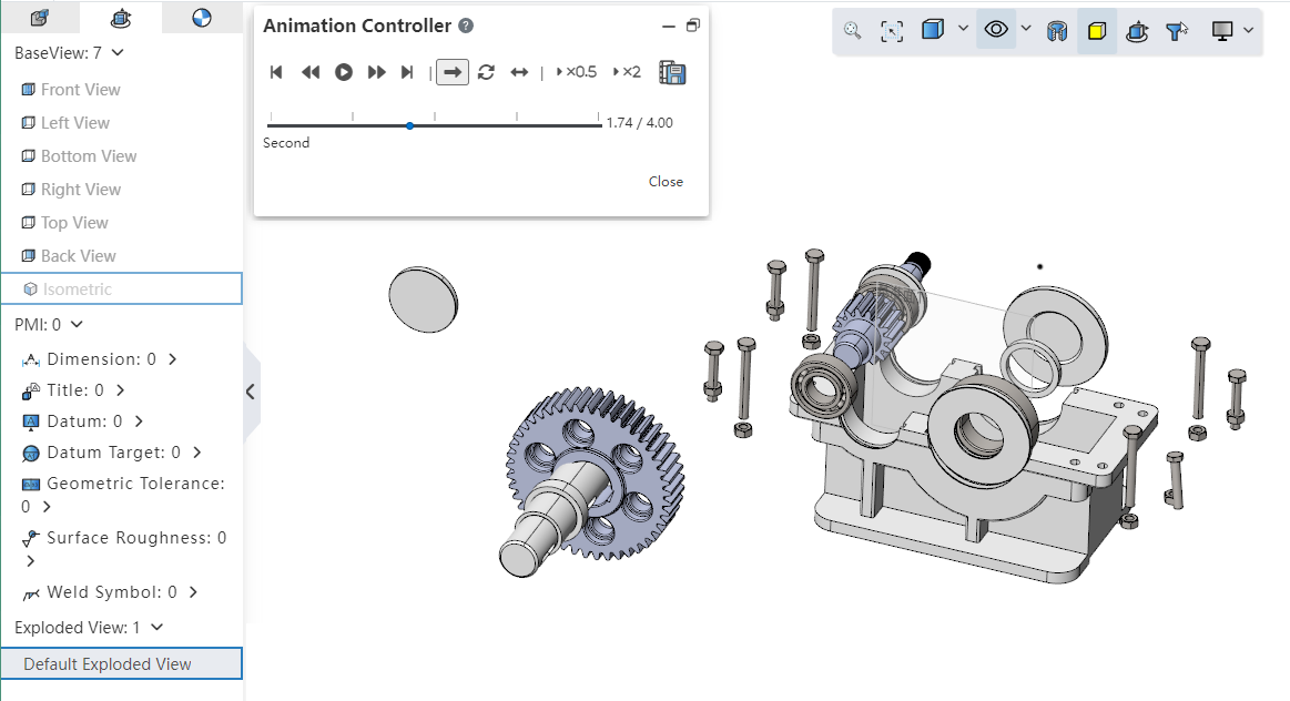
Right click the explosion view and click the "Explosion Animation" option to pop up the animation controller.
Animation controller function description
| Name | Instructions |
|---|---|
| Getting Started | Return the animation to the first screen |
| Last step | Click Pause to return the animation to the previous picture |
| Play/Pause | Play/pause the animation |
| Next Step | Click Pause to return the animation to the next screen |
| End | Move the animation to the last screen |
| Single play | Show the animation once from start to finish, then stop |
| Loop back | Play in a continuous loop (start to end) until you click Pause |
| Play back and forth | A continuous loop of playback (start to finish, end to start) until you click Pause |
| Slow playback | Play the animation at half normal speed |
| Quick play | Play at twice the normal speed |
| Export | Export animation |
Supports exporting explosion animation videos.
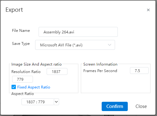
Click the Export button of the animation controller to export the explosion animation as a video.
Export function Description
| Name | Rules |
|---|---|
| File name | Set the video file name |
| Save type | Format the file |
| Image size | Set the video resolution size |
| Fix the width to height ratio | Check this option to select or set the aspect ratio, modify one parameter of the image size, and change the other parameter according to the scale |
| Width to Height Ratio | Select or set the Width/height ratio, available only when the width/height ratio is checked |
| Frames per second | Set the number of frames per second for your video |
# Copy as you go
Support multiple parts to copy.
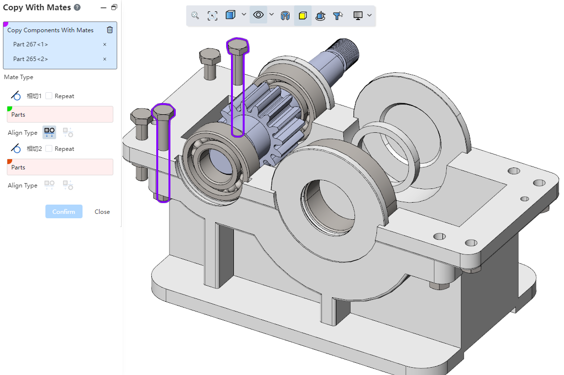
Only top parts can be picked up.
When there is a fit relationship between the picked parts, the corresponding fit is automatically added between the copied instances.
# Drawing
# Views
# Cutaway view
Support split in split, support to make a section view with the section view as the parent view.
When creating a section view, you can directly select the existing section view for cutting.
The results of the sectioning are based on the complete model.
When the sectioned view that is the parent view is reversed, the results of the sectioned view of the child are affected.
# Local view
Local views support custom contours.
How to create: Double-click on the lock focus parent view and sketch the outline in the view. Pre-pick the closed sketch outline, then click the Local View command to create a local view with a custom outline style.
Edit method: Right-click the scope outline on the parent view of the local view that has been created, and click "Edit local View Outline" to enter the sketch editing state. After drawing the outline of the closed sketch, select the outline and exit the sketch to finish editing.
When the outline is not round, you can set the style of the outline in the parent view to "Outline, Circle".
Outline: The outline in the superview is the same as the drawn outline
Circle: The outline in the superview is the outer circle that drew the outline
This option only affects the style of the outline in the parent view, and does not affect the local view display.
# Sheet metal engineering drawings
Sheet metal flat type drawings create clipping views.
# Auxiliary view
Secondary view labels change content and font.
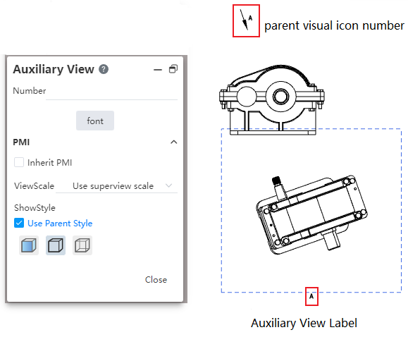
Labels include labels for the parent view and labels for the secondary view.
Modify the label content through the text box of the secondary view.
Modify the font of the label on the parent view through the Font Settings item of the Secondary View dialog box, and modify the secondary view font separately by checking the text of the secondary view.
Each time you change the label font in the Secondary View dialog box, the system will pop up a dialog box asking "Do you want to synchronize to the secondary View label?".
If yes is selected, modify the label fonts for both the parent view and the section view.
Select No to modify only the label font for the parent view.
It is not supported to double-click the view label to modify the content, only through the view dialog box to modify the label content.
# Dimensions
# Base size
Support for creating benchmark dimensioning.
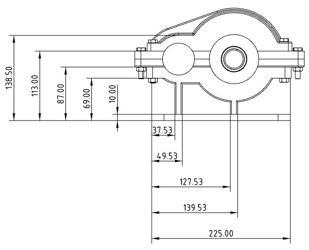
How to create:
1) Click the Benchmark Size command in the Smart Size drop-down box.

Pick up the elements you want to label in turn.
The first element is the base element, and the dimensions between subsequent elements and the first element are automatically labeled.
Press Esc to end the annotation.
Add to Base Group:Right-click the base size, click Add to Base Group, and pick up other elements to add the new size to the base group.
Size move:Distance dimensions in the same direction are combined, angular dimensions are not combined. Drag any size in the group along the direction of the size boundary line, and all sizes in the group move together.
Unalign:Right-click the dimensions in the base size and select "Unalign" so that it is called a separate size note that no longer belongs to that base size. Does not move with other dimensions in the base size and can drag and drop the position independently.
The action to unalign is unidirectional in the base size and does not restore alignment.
Each dimensioning value can be moved independently along the dimensioning line.
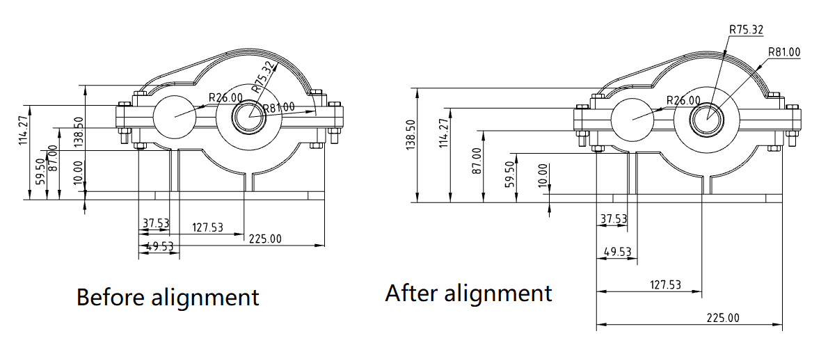
# Automatic size alignment
Multiple selection sizes support automatic alignment.
How to use:
1) Hold down ctrl or box select the size you want to align, and the size toolbar icon  pops up near the mouse.
2) Point your mouse over the icon to bring up the size toolbar.

3) Click Alignment in the toolbar and the dimensions are automatically aligned in the selected way.
Alignment method:
Automatic alignment of dimensions: Automatically adjust the position of dimension lines and dimension values according to the rules.
Linear/radial uniform equidistance: Adjust the position of the size lines so that the spacing between the size lines is evenly distributed.
Collinear alignment: Adjust the position of the size lines so that all the size lines coincide.
Align size lines up/down/left/right: Align size lines to the selected direction.
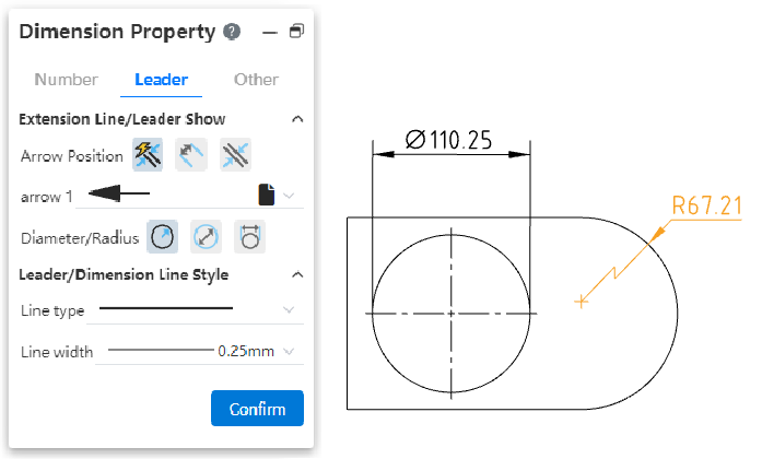
# Refer to dimensions/review dimensions
Click the red box button in the sizing dialog box to create a reference size, review size.
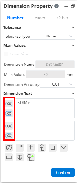
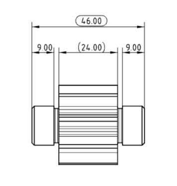
# Fitted tolerances
Dimensional tolerance types support sleeve tolerances.
- Tolerance type:Sleeve tolerance Optional "sleeve, tolerance and sleeve, sleeve (only show tolerance)" three display styles.

Cascading style:This can be used when using "Fit, Tolerance, and fit". When "hole bushing, axle bushing" is set at the same time the tolerance class code, the stacked style of the tolerance class code is controlled.
Classification:This can be used when using "sleeve fit, tolerance and sleeve fit, sleeve fit (show tolerance only)". "User Defined, Gap, Transition, Interference" may be selected.
User definition: can be any combination of "hole sleeve close, shaft sleeve close" tolerance grade code.
Gap, transition, interference: first set the "hole bushing (or shaft bushing)" tolerance grade code, the system automatically selects the qualified "shaft bushing (or hole bushing)" tolerance grade code can be selected.
Automatic calculation of tolerance variables: This can be used when using "tolerance and sleeve fit, sleeve fit (only show tolerance)". Used to automatically calculate tolerance values.
"Hole bushing, axle bushing" only set the tolerance grade code of one of the items, automatically calculate the upper and lower tolerance variables according to the selected and marked size.
When the tolerance grade code of "hole bushing and axle bushing" is set at the same time, this item is not available.
Uncheck this, you can manually set the upper and lower tolerance variables.
Note 1:Sleeve tolerances only apply to length/distance dimensions, not Angle dimensions.
Note 2:The input box of "hole fitting, shaft fitting" can input text to quickly retrieve the required tolerance level code, or you can directly input text, delete the text to clear the options.
# Dimension annotation interactive optimization
A number of adjustments were made to the details of dimensioning interaction to improve the fluency of operation. For example, after marking a size, you can directly select other elements for continuous marking, without first clicking the blank to confirm the generation.
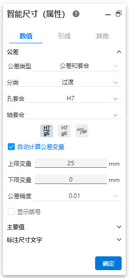
# Circle/arc size lead style
For dimensional labeling of round/arc edges, you can set a variety of lead styles in the Size styles on the dialog Lead tab page.
- Radius Style:New interior lead display effect Settings.

- Diameter style:Added interior lead display effect and number of arrows Settings.
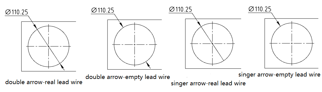
- Linear Style (New):New sets circle/arc dimensioning to linear style. Select and drag the tabs shown by the arrows below to rotate the dimensions around the center of the circle.

# Comments
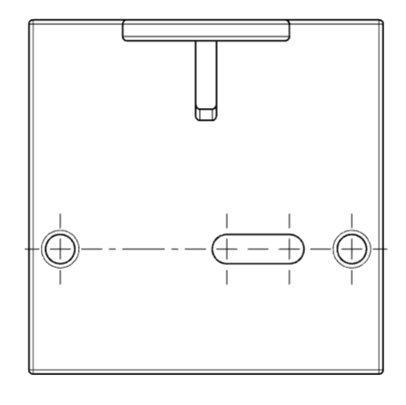
# Center symbol line
- New notch center symbol line annotation.
- Insert method: In the center symbol line dialog box, check "notch center symbol line" and select the edge line of the notch to mark it.
- Notch annotation style:In the center symbol line dialog box, you can choose to mark the end of the straight groove or the center of the straight groove.
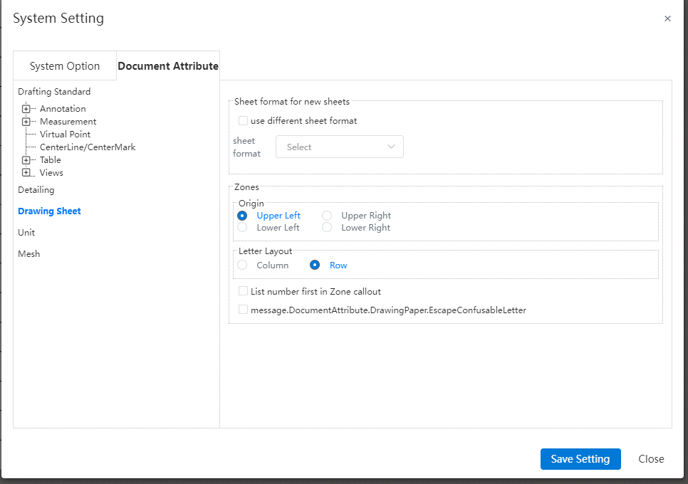
- Slot center symbol line alignment: In "System Settings - Document Properties - Center Line/Center symbol line", you can set the slot center symbol line to align the drawing or align the notch.

- Only the straight groove can be marked, and the arc groove is not supported.
- New automatic insert center symbol line function.
- Insert method: In the center symbol line dialog box "Auto insert option group", check the element to automatically insert the center symbol line, click the view to automatically insert the center symbol line on the corresponding element of the view.
- Description of elements:Hole - round edge, rounded corner - arc edge, slot - straight slot edge.
- Connecting lines can be inserted between the center symbol lines.
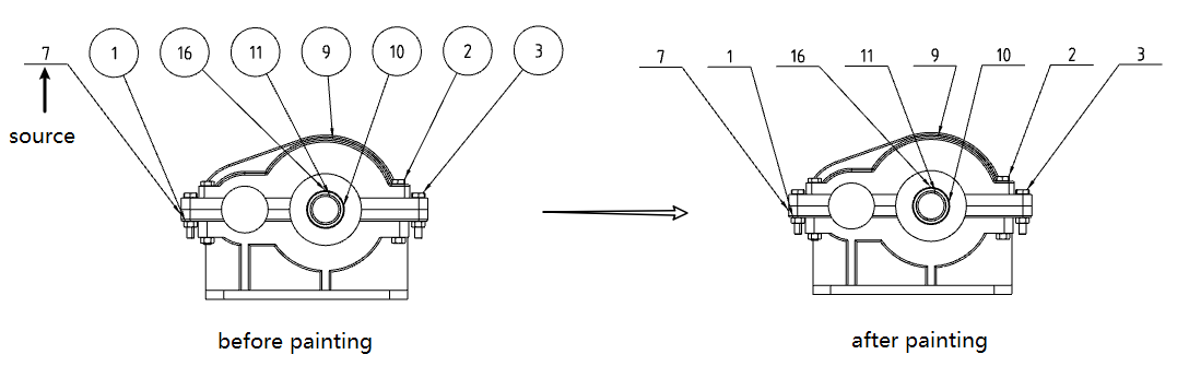
# Magnetic force lines
Added Magnetic Field Lines command in the comment module to generate magnetic field lines for alignment of serial numbers.
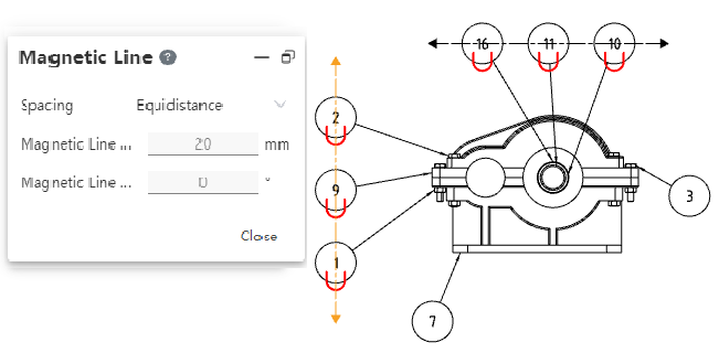
- Manually draw magnetic field lines through the annotation module's [magnetic field line] command, drawing in a similar way to sketch drawing straight lines. The difference is that only one section of line can be drawn, instead of continuously drawing multiple sections of broken lines.
- Magnetic field lines with part serial numbers.
When creating or dragging magnetic force lines, automatically adsorbs around the part serial number.
Only part serial numbers belonging to the same view can be placed on each magnetic force line.
Move the magnetic field line, and the part serial number adsorbed on the magnetic field line moves with it.
Move the part serial number, the magnetic force line remains motionless, you can drag the part serial number from the magnetic force line out to cancel the adsorption effect.
- Magnetic force line can be set parameters.
- Spacing: Set the arrangement rule of the serial number of the part on the magnetic field line, optional "free drag, equidistance".
- Free drag: The serial number adsorbed on the magnetic field line can be dragged arbitrarily within the magnetic field line.
- Equidistance: The serial numbers adsorbed on the magnetic field line maintain equal spacing, and the order can be adjusted, but the spacing between the serial numbers of the parts is always evenly distributed. Minimum spacing 0.5mm.
- Length: Set the magnetic field line length.
- Angle: Set the Angle of the magnetic field line to the horizontal direction of the drawing.
- Magnetic field lines are hidden by default. When any magnetic field line or part serial number is selected, all magnetic field lines in the drawing are displayed, which is convenient to observe the existing magnetic field lines.
# Format coater
- The annotation module adds the Format coater command to paint the formatting of the annotation element.
- How to use:
1) Click Format Brusher to launch the command.
2) Click a comment element in the viewport as the source element.
3) Click or box in the viewport to select another comment as the target element. The format of the target element is painted to the format of the source element.
4) Repeat the previous step to paint the other target elements.
5) Press Esc or the Close button to end the command.
- Can be the type of source or target element: Annotation, dimensioning, form and position tolerances, etc. Table, model edges, or sketch lines cannot be selected as sources or targets.
- Properties that can be copied:
Arrow style
Arrow position (inside, outside, auto)
The border style of the comment as well as the border size parameters
Text font (including font type, size, boldness, tilt, etc.)
Lead/size line style (line type, line width)
Accuracy (including dimensional accuracy and tolerance accuracy)
Color
Tolerances
- Common rules for Format brusher properties:
Apply attributes from the source that can be copied to the target element.
The target element exists, but the attributes that the source does not exist remain unchanged.
# The serial number of the part in the group
- Use the [Part Number in group] command. Select a part as the part pointed by the arrow and generate the serial number of that part. Continue clicking parts and add other parts serial numbers after the first part serial number.

You can set the number of parts serial numbers per line, and the number of parts serial numbers exceeds this number
Allow to click the same part repeatedly, each click to add a corresponding part serial number
2Stacking direction, optional "Stacking right, stacking left, stacking up, stacking down". The number of parts serial number per row/column can be set, and automatically wrap the line/column when the number is exceeded.
3 Frame style, size, text and add quantity of each part serial number can be set separately.
4 One or several part serial numbers can be deleted separately, and the group of part serial numbers disappears after all part serial numbers are deleted.
5 Group of parts serial number right menu content.
| Options | Instructions |
|---|---|
| Remove | Delete the selected part serial number |
| Reattach | Click a part in the viewport to associate the serial number to the newly specified part |
| Add the part serial number to the group | Pop up the group part number dialog box, click the part in the viewport, continue to add the part number to the group part number |
| Sort cascade | Part serial numbers are sorted by default by the order in which the parts are clicked. Click this item to sort the part serial numbers by their size.Note that it is to change the order of the parts serial number, not to change the serial number of the parts. |
# Table
# Hole chart
Added [hole table] command to support the generation of hole tables and corresponding location identifiers.
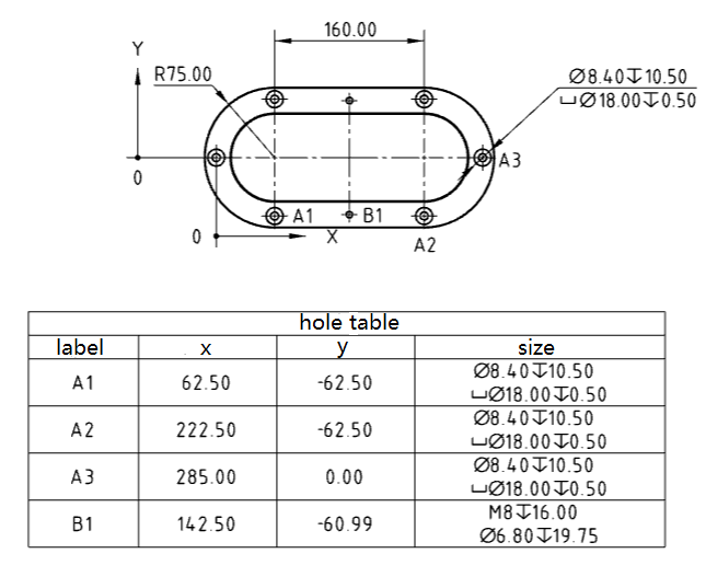
Generation method:
1) Click [hole table] command to pop up the hole table dialog box.
2) Select the default table template provided by the system.
3) Marking order: Expandable option, select XY with radial either way.
4) Reference point: You can select a point to locate the reference position of the hole, where the origin is required, X axis, Y axis is not required.
5) Hole: Select the edge line or face of the hole that you want to add to the hole table.
6) Mark type: Expandable selection, default is ABC, can be switched to 123 mode.
7) Next view: Only available during table insertion process, holes from multiple views can be added to one hole table.
8) Click the left mouse button and the table of bend coefficients is generated at the mouse.
# Bend coefficient table
Added [Bending coefficient table] command to generate sheet metal bending coefficient table.
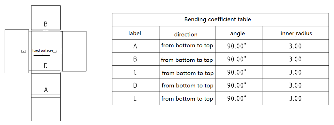
Generation method:
1) Click the Table of Bending Factors command.
2) Set the parameters of the bending coefficient table in the dialog box.
3) Click the Radius Flat Type view in the viewport and preview appears at the mouse.
4) Click the left mouse button, and the bending coefficient table will be generated at the mouse.
Instructions:
A table of bend coefficients can only be created from a flat panel type view, each view can generate at most one bend coefficient table at the same time.
You can set the type of bend label to be letter or number, and the start number of the label.
Constant corners can be set, and the selected boundary is fixed when adding or deleting columns to the table.
Double-click the column header to modify the column properties.
# Table adjusts row height and column width
Table added the ability to adjust row height and column width.
- Support in the viewport drag adjustment row height, column width.
Drag and drop the vertical cell border to adjust the width of the cell column to the left of the border
Drag the horizontal cell border to adjust the height of the side cell row on the border
Drag all four corners of the table to keep each cell row height and column width in proportion to each other and resize the table as a whole.
Double-click the vertical cell border so that the text in the same paragraph in the cell appears as a row, and adjust the column width to fit the row with the most text.
Double-click the horizontal cell border so that the height of the cell fits the entire contents of the cell without changing the width of the column.
- Support right click to adjust the row height and column width.
- Right-click the cell and choose "Column width, lock column width, row height, lock row height, entire table" in the secondary menu of "Format" option.
| Options | Instructions |
|---|---|
| Column width | The Column Width dialog box pops up to change the width of the column in which the selected cell is located.Takes effect only for columns that do not lock column widths, and does not display this item if all selected columns lock column widths. |
| Locking Column widths | Lock the width of the column in which the selected cell resides |
| Row height | Click the Travel Height dialog box to change the height of the row in which the selected cell is located.Takes effect only for rows that do not lock the row height, if all selected rows lock the row height, this item is not displayed. |
| Lock Line Heights | Lock the height of the row where the selected cell is located |
| Entire table | Bring up the Whole Table dialog box and change the row height and column width of the entire table.Takes effect only for rows/columns that do not lock row height/column width, this item is not displayed if the entire table locks row height/column width. |
The Whole table option takes effect for the entire table, and other options take effect for the row/column in which the selected cell resides
When multiple cells are selected, it takes effect for the row/column in which each cell is located.
- The minimum size of the cell should fit exactly all of its contents. When the cell size is not large enough to fit all of its contents, the table size is automatically adjusted.
# Table Template
Support for saving form templates.
- In addition to the "general table" in addition to the "material details, weldment cutting list" and other support the form template function, according to the form type classification to save the template, record the form attribute content.
- Save the form template:Right-click the generated form, choose "Save as template", select "New template" in the pop-up dialog box, and complete the saving after the template name is given.
- Call the form template:When creating the form, select the saved template in the "Form Template" option of the dialog box, and then create the form to generate the table of the content of the selected template.
- Edit the form template:Right-click the generated form, choose "Save as Form Template", select "Replace existing template" in the dialog box that pops up, select the template to be replaced and complete the replacement.
- Manage form templates:In System Settings - Template Management - Form Templates, find the corresponding type of table, such as Material Details, which displays all user-defined saved templates. You can delete, rename, and adjust the order.
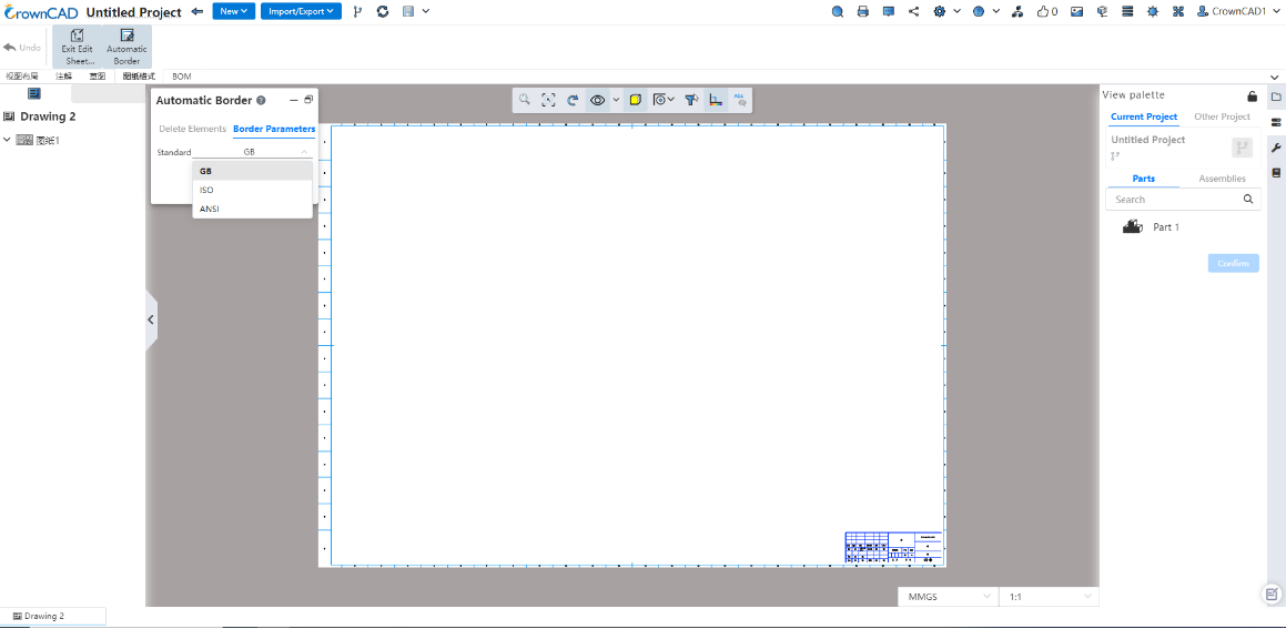
# Automatic border
Support for automatic generation of drawing boxes and area labels in drawing formats.
- Startup method:In the "Edit drawing format" state, you can choose to start the "automatic border".
- Settings:Provide two types of Settings: delete elements and boundary parameters.

Delete elements: Batch delete unnecessary lines or comments and other elements in the current drawing format;
Boundary parameters: Provide GB, ISO, ANSI three standard boundary parameters, can be set on demand selection, to achieve the setting of the area size of the drawing frame, margin, etc.
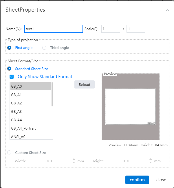
# Customize the drawing size
Support for custom drawing sizes.
- Startup mode:Right-click Drawings on the left of the project drawing and choose Properties from the shortcut menu to open the Drawing property setting box.

- Drawing properties:Standard drawing size and custom drawing size can be selected.
1) Standard drawing size: that is, drawings that meet GB, ANSI, ISO three standards;
2) Custom drawing size: you can specify the size of the drawing by entering the width and height. Allowable range with [0.001, 10000000], in mm.
- Area parameters:Set area parameters such as area size and margin, which are consistent with the property Settings of the engineering drawing.

1) Area size - distribution:
50mm from center: Divided into zones at 50mm intervals from the center of the total division area to the four sides.
Average size: Specify the number of rows and columns, dividing the total division area evenly into areas with a specified number of rows and columns.
- Area size - Area:
Boundaries (default) : Offset the top, bottom, left and right sides of the drawing inward by a certain distance to generate boundaries, and the area enclosed by the boundaries is used as the area to be divided.
Drawing: The entire drawing serves as the area to be divided.
Borders: When the total division area is set to "Borders", control the distance of the borders to the right and left above and below the drawing.
You can jump to "System Settings - Document Properties - Engineering Drawing Drawings" to set other parameters of the area.
- Origin:Set the area number from that corner, specify a corner in the "top left (default), bottom left, top right, bottom right" of the four corners. If "Top Left" is selected, the area in the top left corner is area A1, and the other areas are sorted to the right and down in order.
- Letter layout:You can set letters to represent rows or columns. When letters represent rows, numbers represent columns; Vice versa when letters represent columns, numbers represent rows.
- List the numbers first in the zone annotations:By default, the zone annotations are the letters first, such as A1, B3, etc. Check this to make the numbers come first, such as 1A, 3B, etc.
- You can set whether to skip the confusing letters:I,O,Q,S,X,Z。
Instructions:When the drawing size is customized, the drawing format content is blank, and the drawing frame title bar is not automatically generated, etc., and the user can add it by editing the drawing format function.
# Multiple BluePrints
Supports the creation of multiple drawings in a single drawing document.
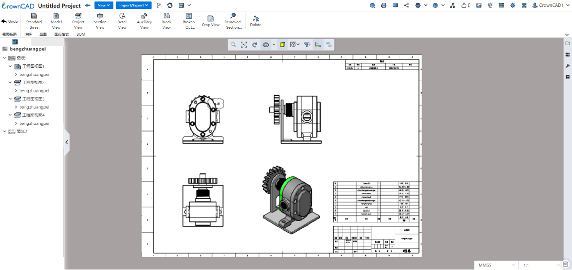
- New drawing:Right-click the drawing in the view panel and select "Add Drawing" to automatically generate and activate the new drawing.

- Activate a drawing:Right-click a drawing that is not activated in the view panel and select "Activate" to activate the drawing. You can also activate a drawing by double-clicking on an inactive drawing.

Delete the drawing:Right click on the drawing in the view panel and select "Delete the drawing". The dialog box to confirm the deletion will pop up and delete the drawing after confirming.
Note: When deleting a currently active drawing, the first drawing in the remaining drawings is automatically activated.
Copy a drawing:Right-click a drawing in the view panel to select Copy. The location of the copy of the optional drawing is "before the selected drawing, after the selected drawing (default), at the end".
Note: The first of the remaining drawings is automatically activated when the current active drawing is deleted.
Association of drawings within the same engineering drawing:
1) The view serial number of all drawings in the engineering drawing is related;
2) Revision table in multiple drawings can be set link or independent in "System Settings - Document properties";
Link: Create a copy of the revision form of the first drawing in all drawings, and update all tables simultaneously when the revision is made.
Independent: All revision forms are independent of each other, and updates made to a revision form on one drawing will not be reflected in tables on other drawings.
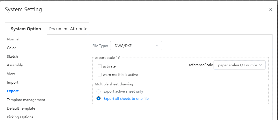
- When exporting DWG and DXF, you can set the export mode in System Settings - Export. Optional options are Output only activated drawings, output all drawings to a single file, and output all drawings to a file.
# Import DWG as template
You can save imported DWG, DXF drawings as engineering drawing drawing templates.
- Startup method:Open the imported DWG and click "Save as engineering drawing template" in the save.
- Through the selection of layers, you can determine the DWG elements saved to the template.
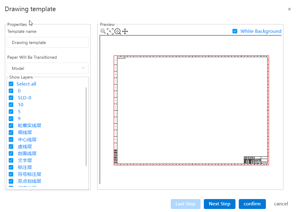
- You can set the drawing size of the template (template or custom), positioning and scaling ratio.
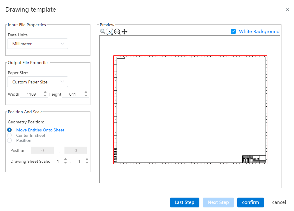
- Support to set the template area size and boundary. (Same as the Settings in the custom drawing size)
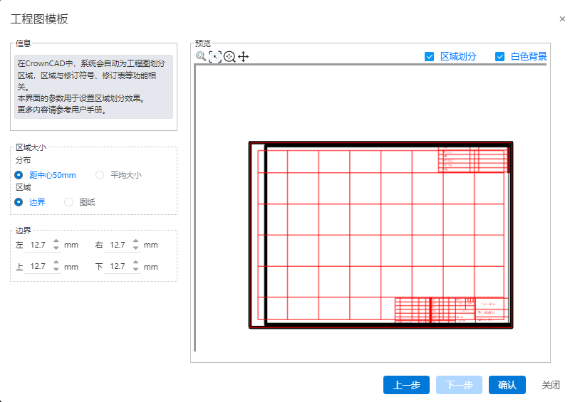
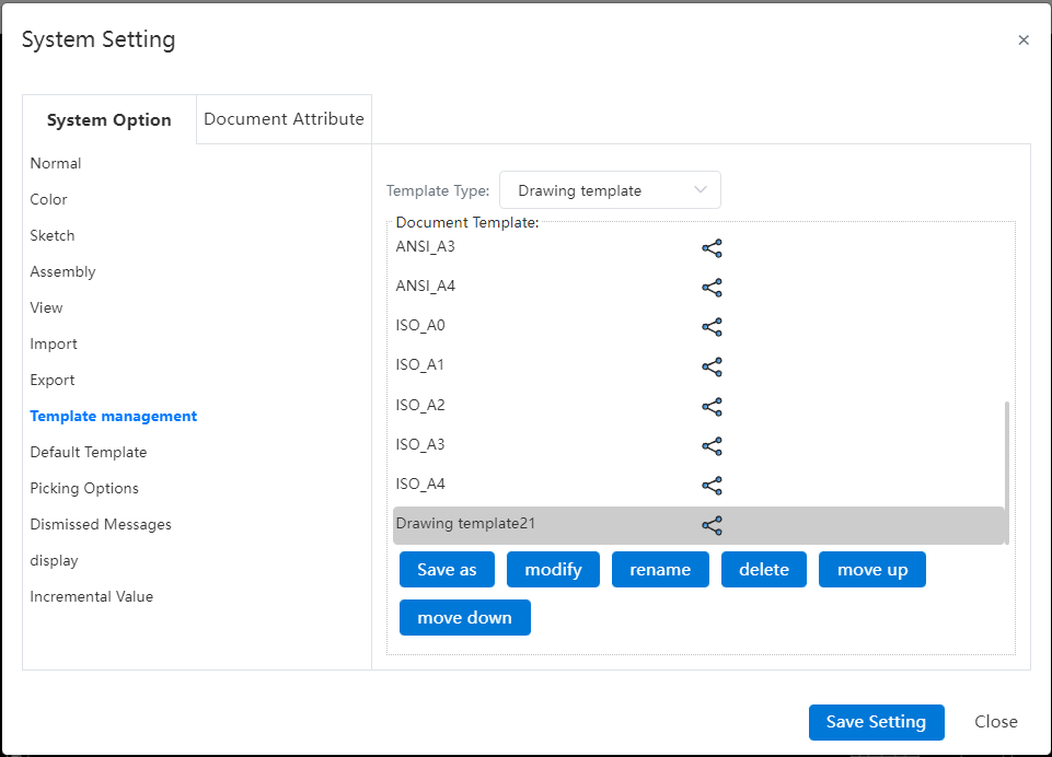
- After the template is saved, it can be managed by "System Settings - Template management - Engineering Drawing Template".
# Line Lines
You can customize the line lines of the model edges as needed to represent information such as annotated revisions.
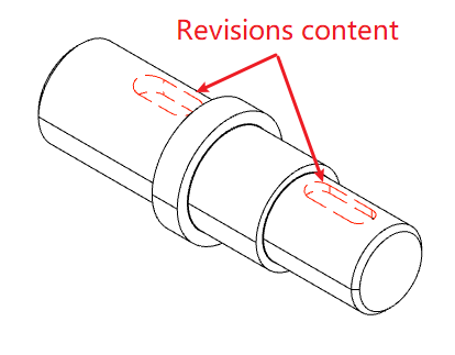
Setting Method 1:Using the Sketch module's Line Line command, select the model projection line you want to modify the line line, set the line line and click OK.
Setting Method 2:Right click to set the model projection line of the line type, click the icon of "Line color, Line width, line type" above the right click menu, and select the style from the drop-down box.
# Apply
# Undo
The engineering drawing module now supports undo actions, which you can do using the shortcut keys (ctrl+z by default) or the Undo button in the toolbar.
Note:Redoing after undo is not currently supported in the Engineering Drawing module.
# Box selection and multiple selection are removed
In the viewport, you can select multiple elements by "box selection" or "shift/ctrl click". The comments and sketches are selected first when the box is selected, and the view can be selected only when there are no comments and sketches in the box selection range.
Select from left to right box, and pick up all the elements within the box selection range. Select from right to left box to pick up all and part of the elements that are within the box selection range.
In-view sketches can only be framed if the view is locked in focus, and in-drawing sketches can only be framed if the focus view is not locked.
In-drawing format elements need to be in the Edit Drawing Format state to be picked up.
In the view panel, you can multi-select the view by holding down shift/ctrl, the same as the document list multi-select document effect.
After multiple selections, you can press delete or delete by right-clicking, while deleting all the selected elements.
# View Alignment
Supports aligning views to any other view within the current drawing, even views with different models can be aligned.
- Alignment Method:Right-click any view, select an alignment method in the secondary menu of view alignment, and click the view to be aligned to complete the alignment.
- Menu options description:
| Options | Effects | Remarks |
|---|---|---|
| Unalign | Make the current view moveable, unaligned to other views. | This item is displayed only when the current view is aligned to other views. |
| Align origin horizontally | Align the model origin of the current view horizontally with that of the specified view. | |
| Align the origin vertically | Align the current view's model origin vertically with the specified view's model origin. | |
| Align the center horizontally | Align the center of the current view horizontally with the center of the specified view. | |
| Align the center vertically | Align the center of the current view vertically with the center of the specified view. | |
| Default alignment | The current view restores its default alignment. | Only views with default alignment, such as Section views, display this item. |
# Sheet Metal
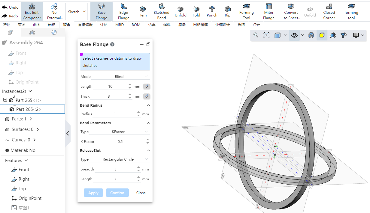
# Base flange
The bending radius, bending parameters, release groove parameters of the matrix flange are the default parameters of the sheet metal body. These parameters are used by default for features such as edge flanges on the sheet metal body.
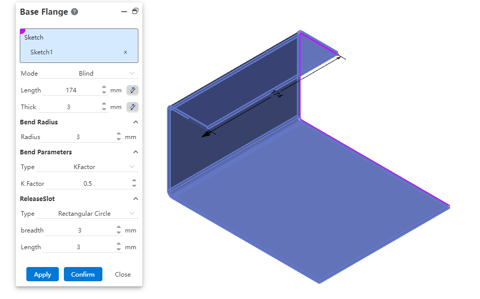
Modify the parameters of the base flange after the sheet metal is created, and update the characteristic parameters of the sheet metal that are not customized in the current sheet metal entity.
If the sheet metal entity exists in the file, run the base flange command to create another sheet metal entity. The default value of the base metal flange is the parameter of the first sheet metal matrix. You can select Overwrite default parameters to customize the parameter.
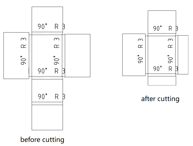
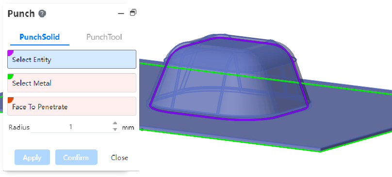
# Stamping
Added picking up entities with rounded corners for stamping.
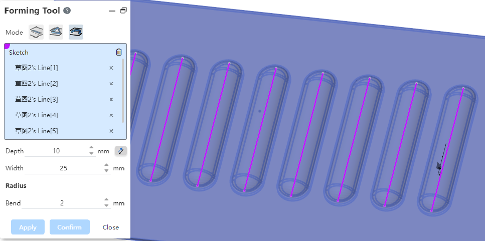
# Molding
The rib method supports picking up multiple unconnected sketch lines to create multiple rims at the same time. Supports the selection of the whole sketch, when the sketch is selected, the lines contained in the sketch are selected, and the connected sketch line is created as one rib by default.
# Pipes
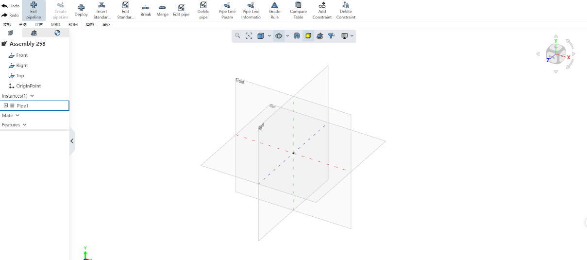
# Line navigation
In the assembly document, you can create pipe documents, and perform pipe design, insert pipe standard parts and other pipe specialized modules. The navigation bar includes creating pipeline documents, designing pipelines, editing pipelines, and pipeline design rules, as shown in the following figure:

The created pipeline can be edited by right clicking or "Enter Pipeline" in the toolbar.
A separate pipe document cannot be generated, but can only be created, edited, etc., in the assembly.
# Creating Piping
Create a blank pipe document in the assembly document.
Click on [Create Pipe]

Document Name: Enter the pipe document name, which defaults to "Pipe 1, 2..." .
Grade Driver: This option is selected by default, and the current saved grade rules can be selected when it is selected.
By default, the first level in the level rule is selected, and other level rules can be selected by dropping down.
Nominal diameter: Displays the smallest nominal diameter in the current class rule. Drop down to select other nominal diameters supported by the class rule.
- Unchecked Grade driver: When unchecked, you need to select the nominal diameter and wall thickness grade.

[OK] Generate the document and enter the edit pipe state, activate the corresponding function of the pipe module.
[Close] Then exit the new pipeline document.
【Note】
The nominal diameter and wall thickness grade determine the diameter and wall thickness of the pipe, and there is no need to manually enter the size.
The pipe designed by the grade rules and the pipe standard parts added meet all the conditions of the grade rules, that is, only the data allowed by the rules can be selected.
In the pipeline document, the grade drive and non-grade drive can be switched freely, but only one grade drive can be selected, that is, the grade can not be changed to other levels after selection.
# Pipe Routing
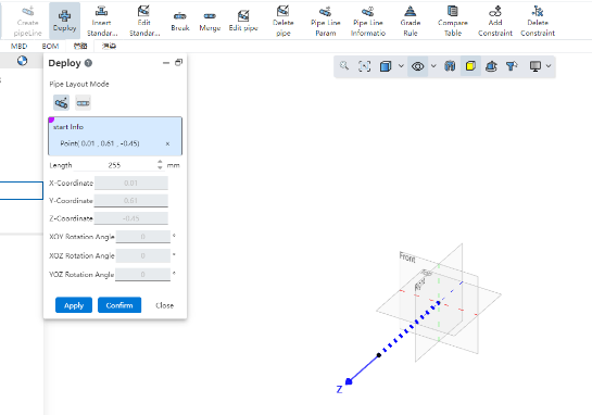
The pipe laying command creates a pipe in a pipe document, creates a pipe path by dragging the axis in the viewport or picking two points, and creates a pipe along the path based on the selected wall thickness grade and diameter.
# Drag and drop the cloth pipe
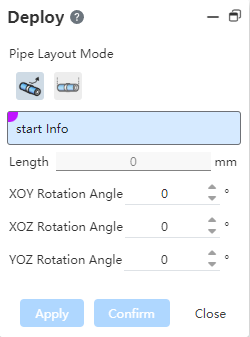
To use:
Select sketch points, solid points, tube midpoints, endpoints, circular edges, or any blank space in the viewport and click to determine the starting point.
After picking up the starting point, the point coordinates are displayed, and the viewport displays a drag-and-rotate coordinate axis with the point as the origin.
Mouse drag axis translation or rotation to create a pipe path, you can also enter the length size or rotation Angle, click apply or OK to create a pipe.
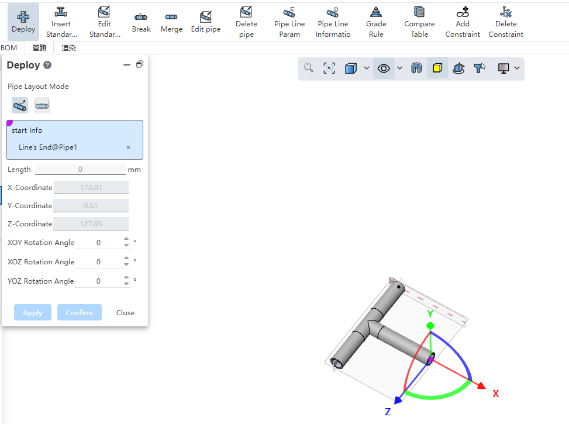
When the midpoint of the pipe is selected, a three-way standard part is automatically added between the original pipe and the new pipe, and the original pipe is divided into two separate tubes.
# Two-point piping

To use:
Select the starting point of the pipe, you can pick up sketch points, solid points, pipe endpoints, circular edges or any blank position.
Select the end point: consistent with the type supported by the starting point.
Click Apply or OK Build Tube.
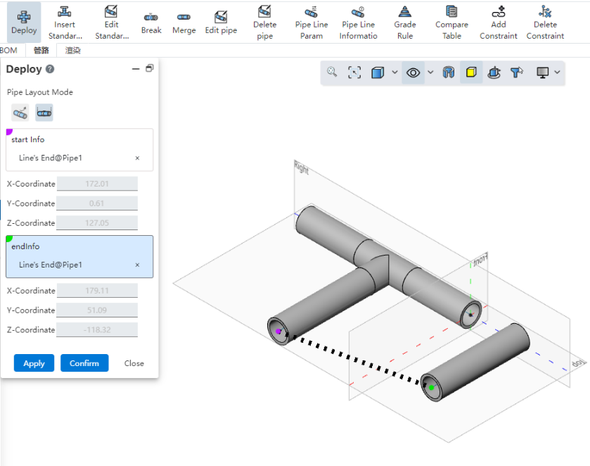
【Note】
When selecting a blank position to do the starting point, you can modify the position by entering the coordinate value.
When the pipe path end is selected to create a connected pipe, the connection is automatically handled according to the type of bend.
# Insert the piping standard
Use this feature to select standard parts from the Piping standard Parts library to insert into the piping document.
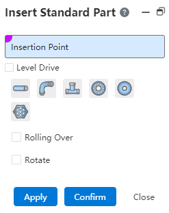
How to use:
Select insertion point: The end point on the pipe path line.
Grade drive: If checked, you can only select the standard parts under the grade rules, if unchecked, you can select any standard parts in the standard parts library.
Select the standard parts type, parts, specifications, grade drive automatically add the same size of the standard parts, do not need to select the size of the specification.
Flip: After checking, mirror flip of the standard parts relative to the insertion point.
Rotation: After checking, you can set the rotation Angle value of standard parts.
Click Apply or OK to complete the standard part insertion, close to exit.
# Edit the piping standard
Use this command to modify the specifications of the standard parts.

How to use:
- Select a standard part from the viewport or instance list.

Displays the current standard part specification, drop down to change to other specifications.
Click Apply or OK to save the changes, close to exit.
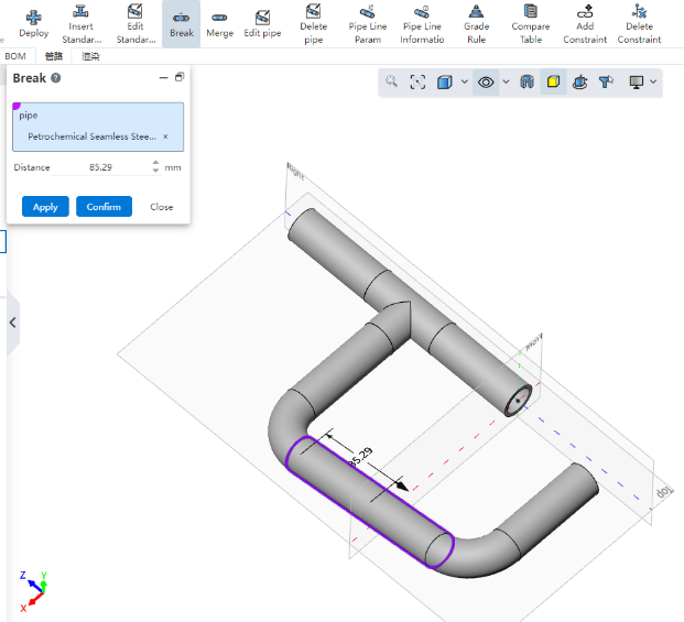
# Interrupt
Use this command to break one pipe into two connected pipes.

How to use:
Choose a tube to break.
Distance: Enter the value of the distance between the breakpoint and the starting point of the tube, or drag the distance arrow in the viewport.
Click Apply or OK to automatically break the tube into two, close to exit.
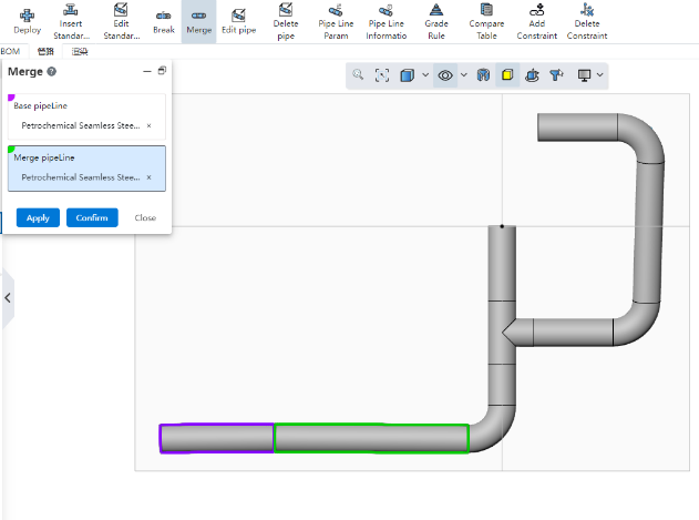
# Merge
Use this command to merge multiple coaxial and continuous tubes into a single tube.

How to use:
Matrix pipe: This pipe as the matrix of the combination, can only pick up a single pipe.
Combined pipe: pipe to be combined, multiple pipes can be picked up, must be coaxial with the matrix pipe and continuous.
Click Apply or OK to merge multiple tubes into one, close to exit.
# Edit Tubes
Use this command to modify the diameter or length of a single section of pipe.

How to use:
Select the pipe whose diameter you want to modify in the viewport or instance list, only one section of pipe can be selected.
Display the nominal diameter and length of the selected pipe.
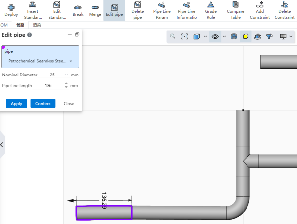
Modify the diameter or length.
Click Apply or OK to complete the changes, close does not save and exits.
After the length of the pipe is modified, the position of the pipe and standard parts associated with it is automatically updated.
# Removal of pipe
Use this command to remove tubes or standard parts from a line.

How to use:
Pick up the tubes and standard parts to be deleted in the viewport or list.
Click Apply or OK to finish deleting.
You can also delete using the right click Delete function.
# Pipe parameters
Use this function to display the current pipe parameters and modify them.
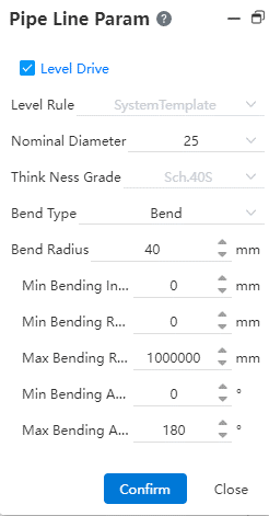
How to use:
- Level driver: If the level driver has been selected when creating the document, it is checked and the level name is displayed. At this time, the check can be turned off, but it cannot be changed to other levels; If the level driver is not selected when creating the document, it can be checked and select a level. When the grade driver is not checked, the nominal diameter and wall thickness grade options are displayed.

Nominal diameter: Displays the nominal diameter of the current line, and can drop down to select other sizes.
Bending type: The processing method of the pipeline at the bend point, including bending and bending, each corresponding to different parameters.
Bending: The parameters include bending radius, bending quantity, maximum and minimum bending radius.
Elbow: Elbow for equal diameter elbow standard parts, no need to set parameters, when the pipe selection elbow, in the viewport according to the rotation Angle (45° or 90°) automatically add the category of standard parts.
Minimum/maximum length: The length limit of each section of pipe can be set.
Click Apply or OK to complete the parameter configuration.
【Description】
After the modification of pipeline parameters, only the newly generated pipeline will be used, and the pipe generated before the modification will retain the previous parameters.
A pipeline document can only use one grade rule or select a non-grade drive.
# Piping Information
Run this command to view the attributes of all pipe components in a pipe document and export the pipe information as a local document.
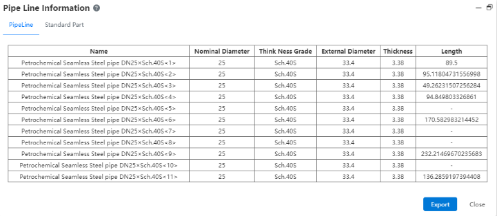
How to use:
Pipe: Display the property information of all pipes in the pipe document.
Standard parts: Displays the property information of all standard parts in the pipe document.
Export: You can export the information about the pipe or standard component to a local Excel file.
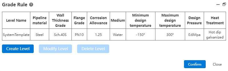
# Grade rules
Use this command to create or manage grade rules. The grade rules can specify information such as pipe material, wall thickness grade, nominal pressure, temperature range, etc., and can also be filtered in the standard parts library according to the rules set by the grade.
The grade rule can specify the pipes and standard parts that meet all the conditions of the grade rule. When the grade rule is selected, only the data allowed to be used by the rule can be selected.
After the grade is selected, it can be [edited] or [deleted].
# Create a rank
To create a new rank rule, go through the following steps:
- Click on [Create Level]
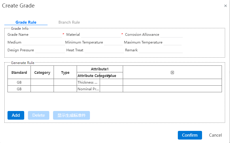
Grade information: Contains grade name, material, corrosion margin, etc., marked with * are required fields.
There are two rules in the generation rule: pipe and flange, the value under the attribute category can be selected in the option of the attribute value, such as the nominal diameter of the minimum value of 25, the maximum value of 100, then only the nominal diameter in this range can be used under the grade.
Click [Add] to add a new standard part and the attribute information of the standard part. The newly created standard part is selected by default. The standard displays GB unmodifiable by default, and the category and type can be selected by dropping down.
Properties: Includes the property category and the corresponding value.
After selecting an attribute category, the value corresponding to the attribute category is automatically filtered.
Click "⊕" to add new attributes. Each attribute is a condition for screening standard parts, and each attribute category can only be added once. When the selected part does not have this property, the default is empty and does not filter.
The property is not required and can be left blank.
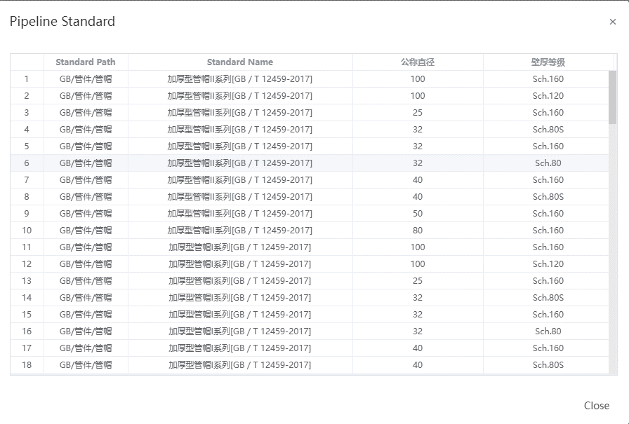
- 【 Show the generated standard parts 】 This button is available after the rule is selected. Click to view the detailed list of the generated standard parts under the rule.
After a rule is selected, it will enter the editing state by default. You can edit it by clicking the drop-down button. Click Delete to delete the rule.
Click OK to save changes and return to the previous level page, close do not save changes.
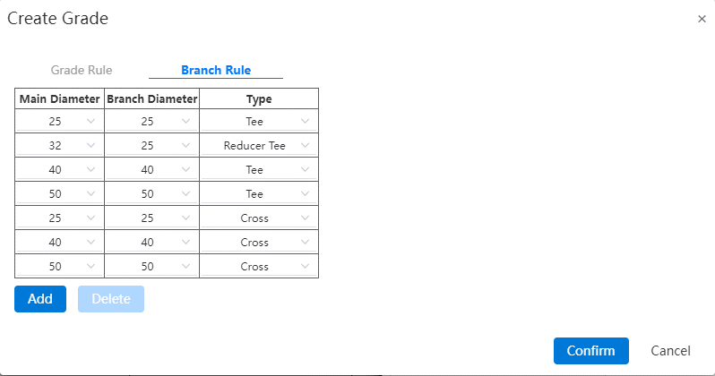
# Branch Rules
Branch rules consist of main diameter, branch pipe diameter and type, branch rules can be added or removed as required.
How to use:
- Click Add to display the selection
Main Diameter: Drop down to select all pipe nominal diameters selected in the grading rules. If the nominal diameter of the pipe defined in the grade rule is 25~100, only the nominal diameter in this range is displayed.
Branch pipe diameter: shows the diameter of the branch corresponding to the main diameter, but cannot be greater than the value of the main diameter.
Type: Equal diameter tee, reducing diameter tee, equal diameter four, reducing diameter four.
[OK] Save the changes and return to the previous level page, [Apply] Save the changes but do not exit the page.
The branch rule is used when creating the pipe, and can only be used when creating the pipe automatically adding tee if the type and the branch pipe diameter under the type are added. Only the diameter relationship of the branch tee (four) is defined here, and the corresponding tee (four) can be used only when the corresponding tee (four) is added in the grade rule.
# Comparison Table
Pressure table, nominal diameter table and end face type table are provided, and the table content can be added or deleted.
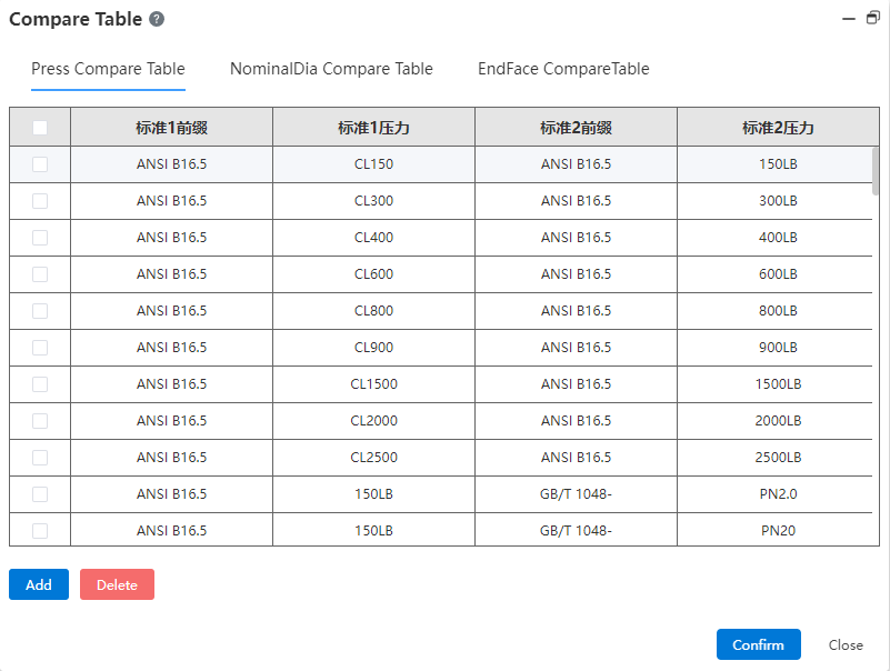
- Pressure comparison table: shows different expressions of pressure levels under different standards, that is, the equivalent relationship between pressure levels under different standards.
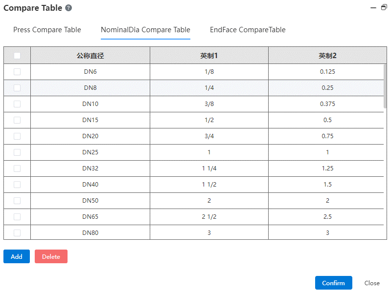
- Nominal diameter comparison table: shows the equivalent relationship between different expressions of different nominal diameters.
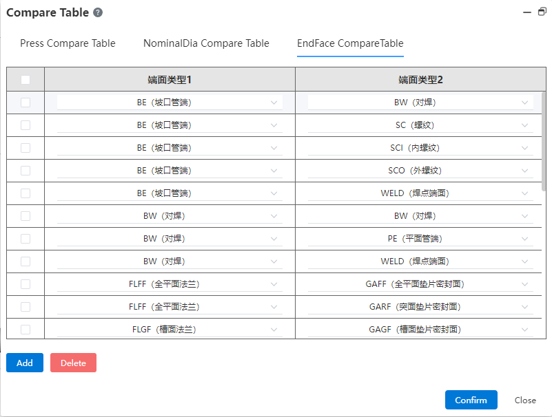
Face type comparison table: provides face type matching rules, according to which to judge the rationality of the connection relationship between the pipe standard parts in the pipeline model. Click the drop down button to select the end face type.
【 Add 】 : You can add a new column in the comparison table, and input data after adding; [Delete] : Select a column and click to delete it.
【 OK 】 Finish the current change and save, 【 Close 】 exit.
# Add constraints
Use this command to add constraints between pipe paths and external parts, or to other paths.

How to use:
Elements: Pick up the pipe path line, the end point of the path line, the midpoint, and the external point.
Constraint type: Points overlap, along the X axis, along the Y axis, along the Z axis. Automatically filter the supported constraint types based on the picked element type.
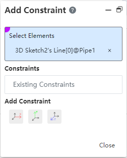
- 【 OK 】 Save constraints and display them on the left constraint tree. 【 Close 】 exit directly.
# Delete the constraint
Use this command to remove constraints that have been added.

To use:
Constraint: Displays the current existing constraint, mouse over the constraint, the corresponding element in the viewport is highlighted, the constraint is selected in the constraint list. Click × to delete it
You can also delete it by right-clicking in the list.
# Emulation
# Structural simulation
# External loads - forces
External Loads - Forces are now supported to be added at the edges or vertices.
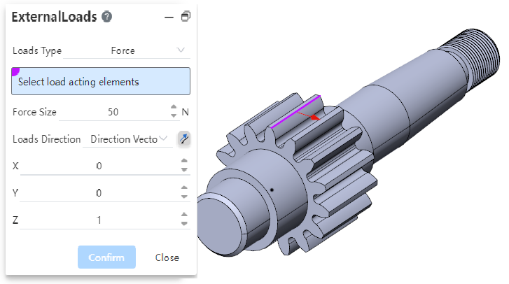
When selecting a point or line, the direction of the force must be specified and "normal" cannot be used.
Points, lines, and surfaces allow mixing of different types of picks and support multiple selections.
When multiple selections are made, the set force is added to each element separately. For example: Select two points at the same time to add 50N of force. Calculate by adding 50N of force to each of the two points, not a total of 50N of force from the two points.
# External load - Torque
External load new torque type.
- Adding Method
Click on the External Load command, the default type is "Force", and change the load type to "Torque" in the External Load dialog box to add the torque load.
Click the drop down arrow of the External load command and select Torque to bring up the External Load dialog box and check the "Torque" type by default.
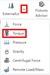
Right click on "External Load" in the simulation panel, click on "Torque" option, the External Load dialog box pops up and the "Torque" type is selected by default.
2 The torque load can only be applied to the surface, the surface can be any shape, the cylindrical shape is preferred. Through the distance of each point on the surface relative to the torque axis and the torque size, the magnitude and direction of the force at each point are calculated. When multiple selections are made, the set torque is added to each element separately.
3 The axis on which the torque needs to be specified can be picked up cylindrical or straight. Reverse is supported.
# External load - pressure
External load Added pressure type.
- Adding Method
Click on the External Load command, the default type is "Force", and change the load type to "pressure" in the External Load dialog box to add the pressure load.
Click the drop down arrow of the External load command and select pressure to bring up the External Load dialog box and check the "Pressure" type by default.
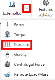
Right click "External Load" in the emulation panel, click the "Pressure" option, the External Load dialog box pops up and the "Pressure" type is checked by default.
2 The pressure load can only be applied on the surface. For multiple selections, add the set pressure to each element separately.
3 The pressure load is supported along the normal direction of the surface or the given direction vector, and both ways should support reverse.
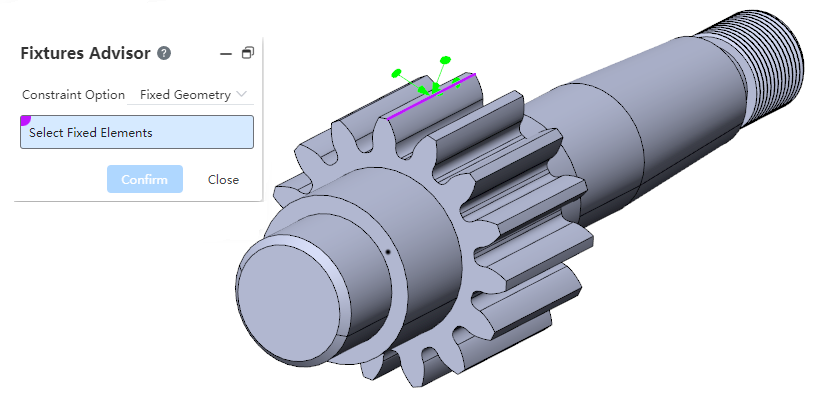
# Boundary constraints
Boundary constraints - Fixed support added at points or lines.
# Contact - Rigidity
Support for adding rigid type of contact between entities.
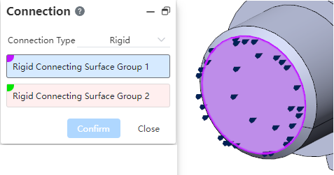
- Click the [Connect] command in the menu bar and select two groups of faces to add rigid connections
The two sets of faces should come from two separate entities
The faces must be from the entities included in the analysis 2 Surfaces that add a "rigid connection" are treated as "rigid bodies" that do not deform for the purpose of analysis, and both sets of surfaces move together and are stressed together.
3 Rigid connection right-click menu content: "Edit, Delete, hide, suppress"
Edit: Pop-up dialog box, re-edit
Delete: Delete this connection
Hide: Controls the appearance of symbols in the viewport.
Suppressed: The suppressed connection can be suppressed or unsuppressed. The suppressed connection does not participate in the calculation
# Generate reports
You can now select what you want to include in your report.
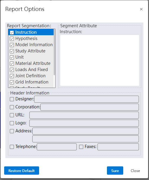
What to include:
| Sections | Content |
|---|---|
| Title | Set the designer, company, etc. information as needed |
| Instructions | User defined text |
| Hypothetical | User defined text |
| Model information | All references cite information such as the names of parts and sub-assemblies |
| Example properties | Including example name, analysis type, and grid type of solving information |
| Units | Unit system: · Length/displacement · Temperature · Angular speed · Stress/pressure |
| Material properties | · Material details such as name, yield strength, tensile strength · Material table values and diagrams · Customize the material description information · Custom material properties defined by the user for the custom material |
| Loads and fixtures | · Payload name, image and details |
| Joint definition | · Joint type and details· Joint force |
| Grid information | · Grid details and images· Grid control information (name, image, and details) |
| Example results | Image and parameters of the result. |
| CONCLUSION | User defined text. |
| Addendum | Support for selecting local files, insert into documents. |
- The "Title" section checks and adds information in the title information.
- "Title - Logo" requires the user to upload a picture.
- The "Description, Hypothesis, Conclusion" section requires custom text to be entered by the user, which is blank by default.
- Other sections can add comment text, which is added at the end of the entire section.
# Data conversion
# Import
Support import ppt, word, you can perform a simple preview and source file download.

Supports the import of files with special characters in the file name.

Support reading PMI information of SW documents.
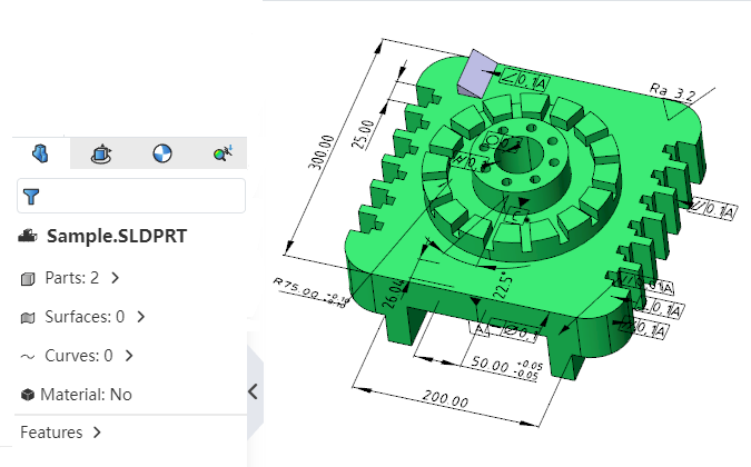
# Exports
When exporting parts/assemblies, you can choose whether to export entities/parts in a hidden/unloaded state.
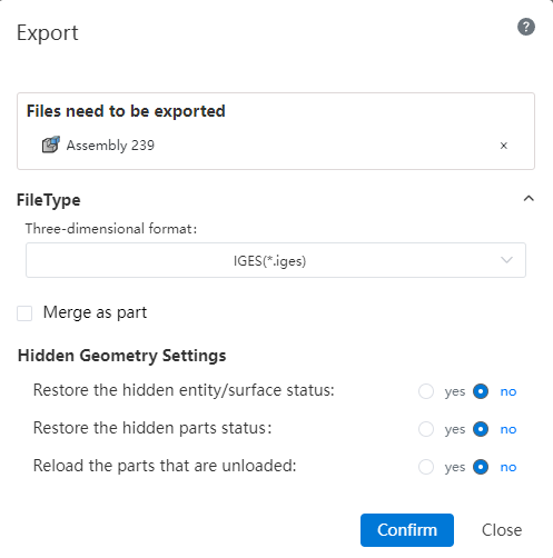
Note:Check the "Yes" option in the Hidden geometry Settings and the relevant geometry will be displayed and exported.
# Apply
# Select filter
Use the Select filter function in the parts/assembly/drawings to filter the currently pickable elements.
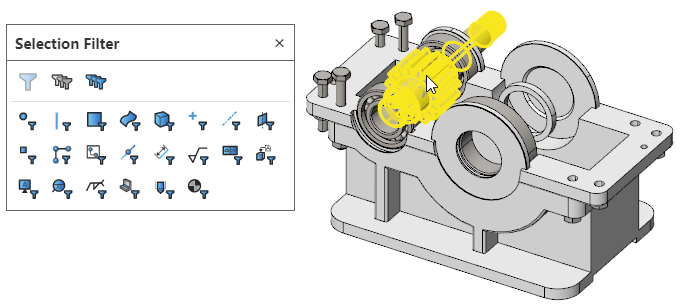
How to use:
Click the "Select Filter" icon on the toolbar of the leading view to bring up the "Select Filter" toolbar.

Click the icon of the element type in the toolbar to highlight it, controlling that only the highlighted elements can currently be picked up.
Click the highlighted element again to make it unhighlighted, and select Filters to automatically deactivate when none of the elements are highlighted.
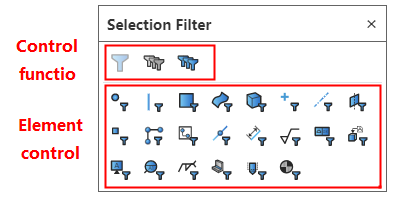
Click the control icon on the toolbar to activate/deactivate filters, Clear all types, Select All Types.
Function description:
Filter rules:
Do not start the command, only the elements belonging to the filter type can be picked up.
Start any command, and the command is in the state to pick up a specific element (such as the stretch boss to pick up the sketch or to pick up the draw direction), if the specific element overlapped with the element set by the filter (such as the filter selected the axis), then only the overlapped element can be picked up (that is, only the axis can be selected, no other direction elements can be selected); If the specific element does not coincide with the element set by the filter (such as the filter selects the entity), the filter does not take effect (that is, any direction can be picked up elements).
Start the measurement command to pick up only elements that belong to the filter type.
Elements that are originally hidden or cannot be picked up due to occlusion can still not be picked up after "Select Filter" is set.
The filter toolbar can be hidden while the filter is activated, please note that the filter is still in effect at this time.
Default shortcut keys: F4- Explicit Select filter toolbar, F6- Activate/deactivate Select filter.
# Feature Panel
A screening box is displayed above the part feature panel. Enter keywords in the screening box to display the screening results in real time.
# View/Render
# Set the look
# Appearance hierarchy
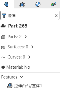
Part Documentation:Add part appearance in Set Appearance Type
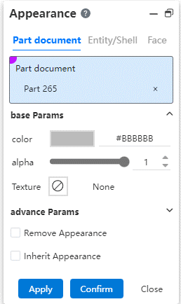
- Appearance display priority:Part appearance < body appearance < surface appearance.
Assembly documents:Divided into "Apply to parts, Apply to documents" two tab pages.
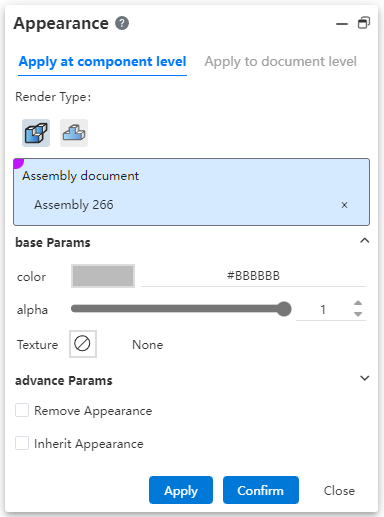
Apply to Parts:Pick up assembly documents and top parts set appearance, set appearance cannot be applied to parts and sub-assemblies, only saved in the current assembly.
Assembly: Only the current assembly document is picked up.
Parts: Pick up the top parts or sub-assemblies in the assembly.
Automatically select assembly and fill when opening the function, consistent with the appearance function of the part in the part.
Apply to the document:Pick up top parts, entities, surfaces set appearance, set appearance directly to the parts and sub-assembly.
Parts: Pick up parts or sub-assemblies in an assembly, which can be multi-level.
Solid/surface, surface: consistent with the appearance function set under the assembly in the part.
The priority shown in the final assembly document: Assembly appearance > Parts (assembly layer) appearance > Surface appearance > Body appearance > Parts (part layer) appearance.
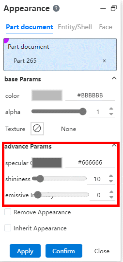
# Advanced parameters
Add advanced parameters to Set Appearance.
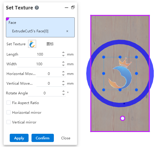
# Custom textures
Supports setting custom stickers for faces.
What to do:
- Stickers can be set in two ways:
Method 1: Select a map in the gallery on the right side of the viewport, drag it to the model surface in the viewport, press the custom map command, and automatically fill the selected surface and map in the dialog box.
Method 2: Click the drop-down button after setting the appearance, select the "Custom map" command, and the dialog box will pop up.
Select a face in the viewport, only one plane can be selected.
Select a map from the map list and a preview appears in the viewport, or click Upload Local Image.
You can change the size and position of a tile by dragging Handle or adjusting parameters in the dialog box.
- Move:Hold down the left button while placing the mouse in a rectangular area
- Rotate:Hold and drag the blue circle
- Resize:Hold down the vertex or midpoint of the rectangle's edge line and drag to change the size
- Click Apply or OK to complete the custom map.
Note:Stickers can be added to both parts and assemblies, adding stickers to assemblies directly affects parts.
# Set
Support custom viewport sets.
Setting method 1: Open the "Appearance, Texture and scenery" panel on the right side of the viewport, switch to the scenery tab page, and directly drag the desired scenery to the viewport area to complete the setting.
Setting method 2: Open the "Appearance Panel" on the left side of the viewport, expand "Scenery and light source", right-click "scenery" and select edit or delete scenery to set.
# Light Sources
Add light source list and add light source function.
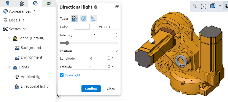
The light source list is located in the left "Appearance Panel" for viewing and editing light sources.
Click the Light Source command in the Render module to create a new light source.
Light source parameters:
Type: Optional Line Light Source, point light source, Condensing source
Color, Intensity: Set the color and intensity effects of the light source.
Light source position: Display and set positional parameters according to different light source types.
Enable light source: Click OK in the rearview mouth when checked to turn on this light source and turn off other light sources; When not checked, only the generated light source is not enabled.
Right click on light source:

Show/Hide light source line: Show light source line in viewport, independent function, independent of whether the light source is enabled or not.
Add Light source: Open the [Light Source] function panel for adding light sources.
Edit Light source: Edit the currently selected light source.
Delete: Deletes the current light source.
Enable/Disable Light sources: Multiple light sources can be enabled at a time, and a mixture of multiple light sources is displayed in the viewport.
# Render Styles
Click the View Settings function in the leading view toolbar to modify the model rendering style.
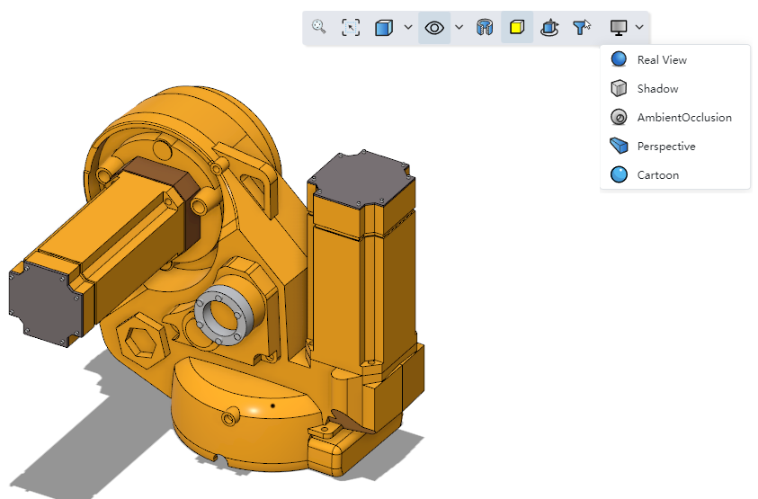
Note:Real rendering and cartoon rendering cannot be turned on at the same time.
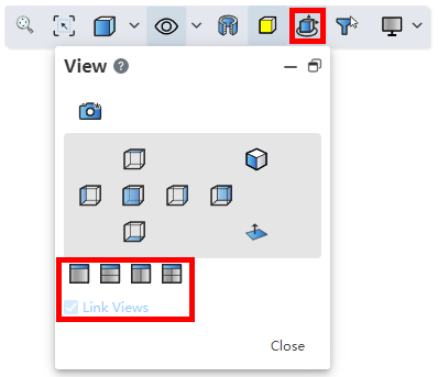
# Multiple Viewports
New viewport option to view models through a single viewport or multiple viewports.
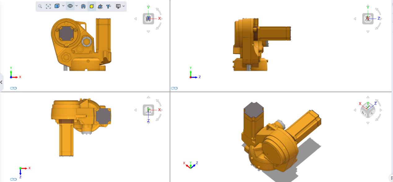
How to open:Click the "View Orientation" icon on the toolbar of the leading view or press the space bar to open the "View" dialog box. Select the number of viewports in the dialog box to open multiple viewports.