# Mate Advanced
# Limit Distance/Angle
Allow parts to move within a certain numerical range of distance fit or Angle fit.
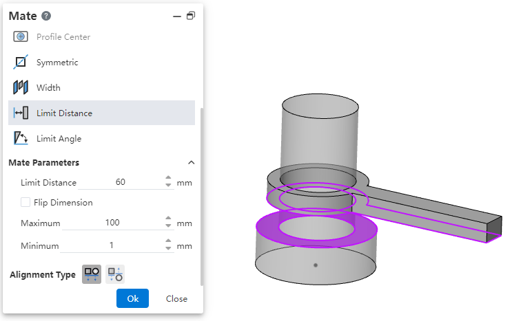
- Limit distance: The distance of the selected element in its current state.
- Maximum, minimum: The limit distance within the range within which the selected element can move.
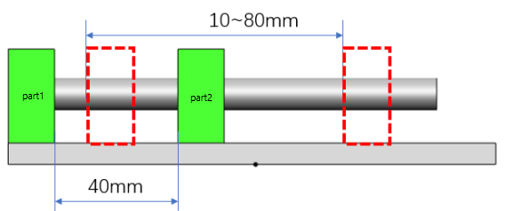
Example: Set the limit distance of part 1 and part 2 to 40mm, the minimum value to 10mm, and the maximum value to 80mm, then the movable range is as follows.
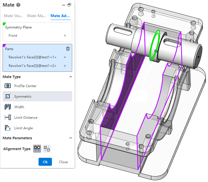
# Symmetric
Make two solid elements symmetrical with respect to the datum or plane.
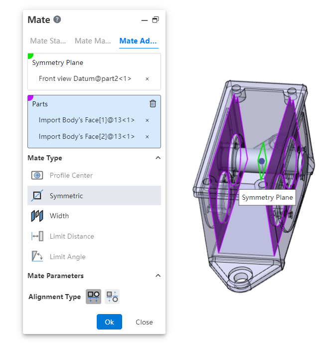
- How to use:Click Fit, switch to advanced fit, fit type select [symmetry].
- Symmetry plane:Select a plane or datum plane.
- Parts:Pick up two solid elements to fit.
- Alignment type:Controls the relative orientation of two elements, including alignment in the same direction and alignment in the opposite direction.
Instructions:
Two solid elements can belong to the same part or different parts.
When picking up two faces of the same part, the two faces must be parallel and the plane of symmetry should belong to the plane/datum of the other part.
The effect of symmetrical matching with the part elements is shown in the following figure:
# Profile Center
Align the geometric outline centers and completely define the parts.
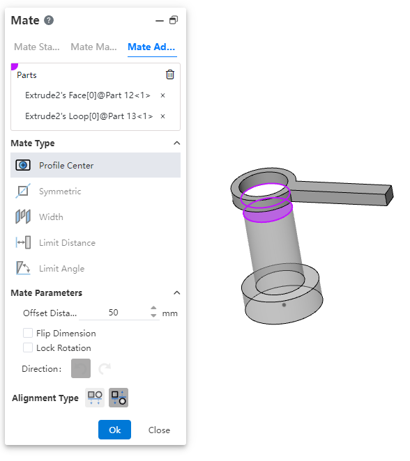
Parts:Pick up sketch lines, edges, or solid faces of the two entities to fit.
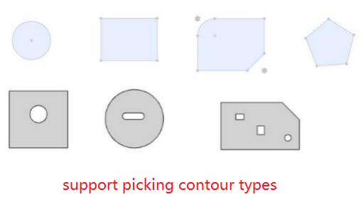
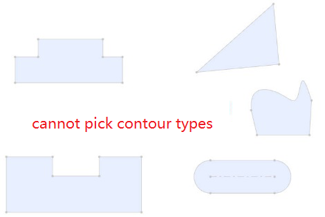
- Element type: Closed loop sketch outline, solid edge line, solid face
- Outline type: full circle, rectangle, regular polygon, rectangle can be chamfered or rounded, face outline can contain cuts inside.
- When picking up solid edges, calculate the center of the contour based on the face on which the edges are located.
Fit parameters:Offset distance, lock rotation, direction.
Offset distance: Sets the offset distance between the centers of two Outlines.
Lock rotation: Select this option when selecting two circular contours to lock the rotation of the part.
Orientation: Use this feature to change the orientation of the part when selecting two non-circular Outlines.
Alignment Type:Controls the relative orientation of two elements, including the same alignment and reverse alignment.
Fit effect:After adding a fit, the contour centers of the two parts coincide, and the constraint state generates different fit effects according to different contour types and options.
When the circular outline is included, if "lock rotation" is checked, it will be completely constrained, and if it is not checked, it can be rotated around the center of the outline.
When circular contours are not included, the parts are fully bound.
# Width
Bind the parts between the two planes.
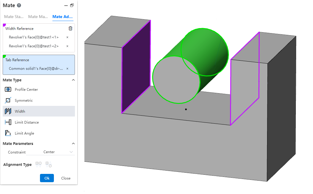
Width reference: Pick up two parallel or non-parallel faces.
Label reference: Pick two parallel or non-parallel faces, or a cylinder.
Constraint: Select the type of constraint, optionally "Center, free, percentage, size"
Center: The label overlaps with the width reference center.
Free: The position of the label in the width reference is not restricted and can be moved/rotated within the width reference.
Percentage: Limits the position of the label in the width reference by percentage.
Size: Limit the label by size to the location of the width reference.
Different combinations of width references and label references support different types of constraints:
| Combinations | Width reference options | Label reference selection | Supported constraints |
| 1 | Two parallel faces | Two parallel faces | Center, freedom, percentage, size |
| 2 | Two parallel faces | Two non-parallel faces | Center |
| 3 | Two parallel faces | Cylindrical faces | Center, freedom, percentage, size |
| 4 | Two non-parallel faces | Two parallel faces | Center |
| 5 | Two non-parallel faces | Two non-parallel faces | Center, freedom, percentage, size |
| 6 | Two non-parallel faces | Cylindrical faces | Center |
| 7 | In combination 1/3/5, the width reference distance (or Angle) is less than or equal to the label reference distance (or Angle, cylinder diameter) | Center | |
Coordination effect:
Center: Label reference the middle surface of the two planes, the axis of the cylinder and the middle surface of the width reference add the coincidence effect
Free: The label reference element is located at any position within the width reference range, and the label part moves/rotates within the width reference range, and stops when the move/rotation reaches the position where the element coincides or is tangent (the effect is similar to the restricted distance/Angle)
Scale: Similar to the constraint of notch scale in mechanical fit
Size: Combinations 1 and 3 show the distance value, combination 5 shows the Angle value, and the label reference is located at the size specified value
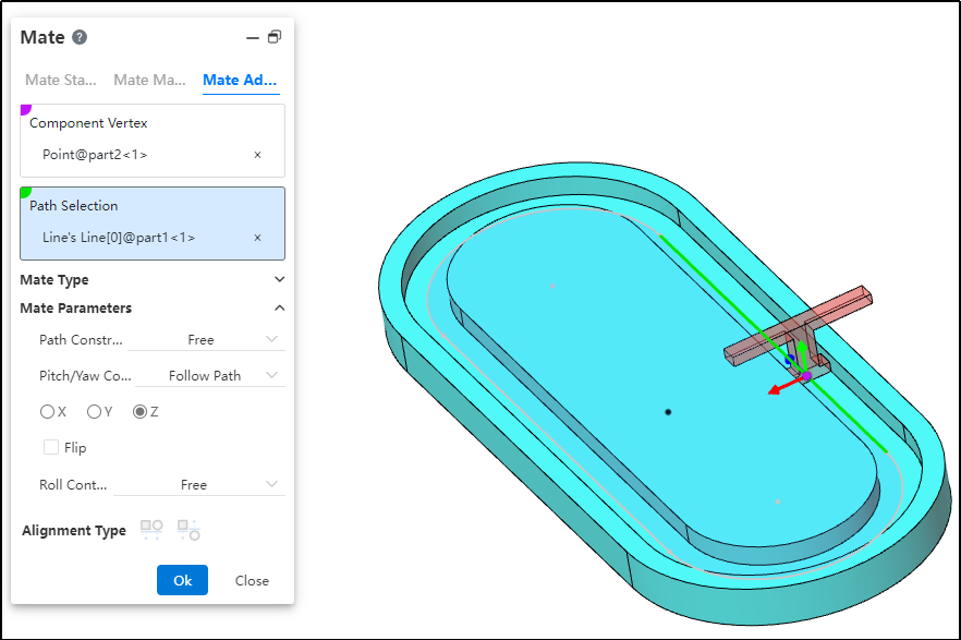
# Path Mate
The path mate constrains selected points on components to a path, and allows users to define deviations, swaying, and other behaviors as the component travels along the path.
How to use:
After inserting the parts, click the "Mate - Advanced - Path Mate" command.
Select the part vertex and pick the point element.
Select the path and pick the sketch profile, solid edge, or curve.
Choose the path constraint type based on your needs.
Choose the pitch/yaw control type based on your needs.
Choose the roll control type based on your needs.
Click OK to generate the feature.
Dialog Box Control Instructions:
Path Constraint: Choose how the component moves along the path.
Free: The component can move freely along the path.
Distance along Path: The component is fixed at a specific distance along the path and cannot move, but can rotate freely around the vertex.
Percentage along Path: The component is fixed at a specific percentage along the path and cannot move, but can rotate freely around the vertex.
Pitch/Yaw Control: Choose the pitch angle and orientation of the component as it moves along the path.
Free: The component can freely adjust its pitch while moving along the path.
Follow Path: By selecting a 3D coordinate direction, the component maintains a consistent pitch orientation during movement.
Roll Control: Choose the roll angle and direction of the component as it moves along the path.
Free: The component can rotate freely while moving along the path.
Up Vector: Ensures the rotational orientation of the component during movement by selecting a constraint element and a three-axis direction.
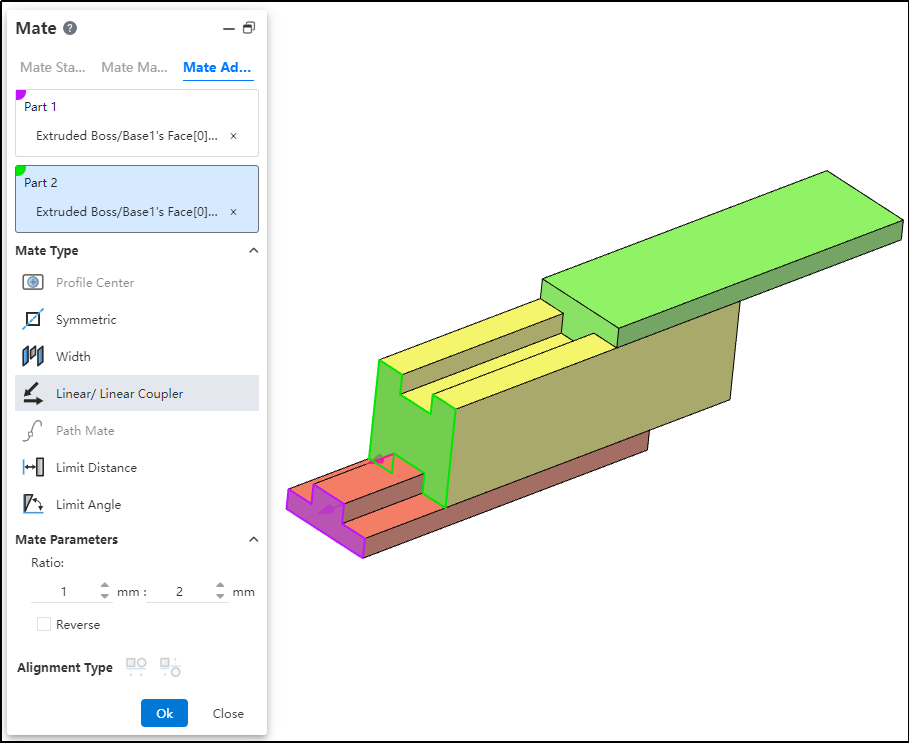
# Liner/Liner Coupler
By establishing a geometric relationship between the translation of one component and the translation of another, motion can be defined for each component relative to the ground or a reference component.
How to use:
After inserting the parts, click the "Mate - Advanced - Linear/Linear Coupling" command.
Select Part 1 and pick the element; this element serves as the reference during linear movement.
Select Part 2 and pick the element; this element establishes a proportional distance relationship with the reference element during linear movement.
Set the ratio.
Decide whether to check "Reverse" based on your needs.
Click OK to generate the feature.
Note: The ratio indicates that when the first component moves a certain distance, the second component moves a corresponding distance based on the predefined ratio relative to the reference. For example, a ratio of 1:2 means that when the first component moves 1 mm, the second component moves 2 mm relative to the reference element.