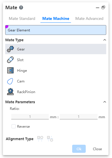
# Mate Machine
# Gear Mate
Make the two parts rotate relative to each other around the selected shaft at a certain speed ratio.
- Parts: Select the cylinder, cone, shaft, straight/circular lines (including sketch lines, solid/surface edges) on two different parts.
- Ratio: Enter two values respectively, the ratio of the two numbers is the ratio of the rotation speed of the parts; The part with the larger value rotates slowly.
- Reverse: Control the direction of rotation of two parts.
- Unchecked by default, that is, relative rotation, such as one counterclockwise and the other clockwise.
- After it is checked, the parts turn in the same direction.
# Slot Mate
Allows you to fit the "cylinder/shaft" to the "straight/circular groove" or the groove to the groove, and supports the "free", "in the center of the groove", "percentage along the groove" and "distance along the groove" constraints.
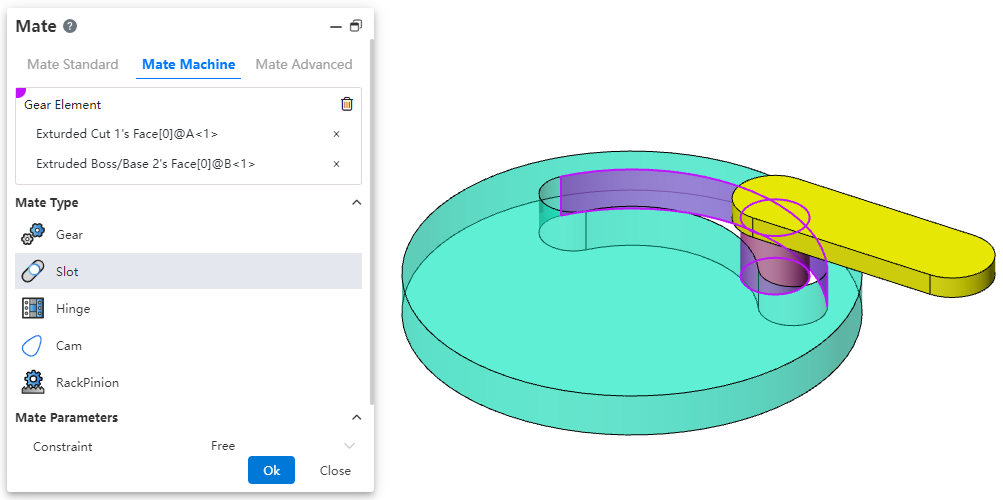
- Parts: Select the elements on two different parts. The elements can be the following combination.
- Combination 1: Straight grooves or circular grooves + cylindrical surfaces.
- Combination 2: Straight grooves or circular grooves + reference shaft.
- Combination 3: Straight grooves or circular grooves + straight grooves or circular grooves.
- Constraint: Choose a positional constraint relationship between two elements. Take the cylinder and notch fit as an example:
- Freedom: The cylinder can move freely within the notch.
- Percentage along the notch: The percentage needs to be set and the cylinder can only be in a fixed position inside the notch.
- Distance along the notch: To set the distance, the cylinder can only be located in a fixed position inside the notch.
- Reverse: Control the direction of rotation of the two parts.
- Unchecked by default, that is, relative rotation, such as one counterclockwise and the other clockwise.
- After it is checked, the parts turn in the same direction.
# Hinge Mate
Components such as hinges for restraining the door.
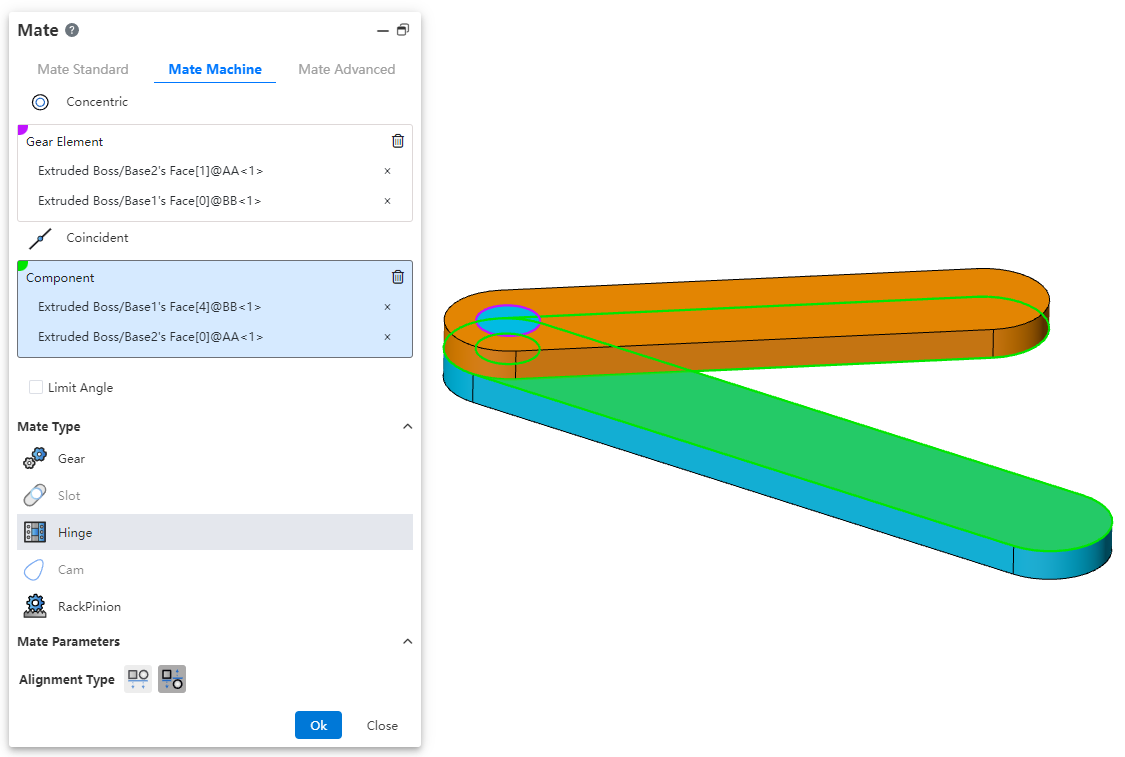
Coaxial part element: Pick up the part element to which you want to add coaxial.
Coincident part element: Pick up the elements of the same part as the coaxial center and add a coincident fit.
The green range below indicates the combination of element types that support picking
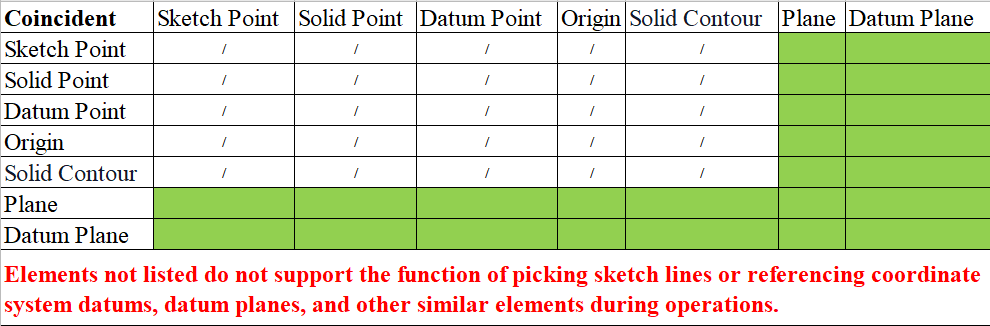
Only elements with the same parts as the axis can be picked up
Limit Angle: Check this, select the plane belonging to the two parts respectively, set the Angle range of the two faces can be rotated relative to each other in the fit parameters.
The green range below indicates the combination of element types that support picking

Only elements with the same parts as the axis can be picked up
Alignment type: In the same direction or in the opposite direction, the button is available only after both coaxial and coax are selected.
Constraint effect: when the limit Angle is checked, the part becomes fully constrained, but it still supports rotation within the Angle range; When it is not checked, the effect is equivalent to adding coaxial and coincidence constraints.
# Cam
This fit ensures that the cam maintains the correct motion and position of the follower during operation.
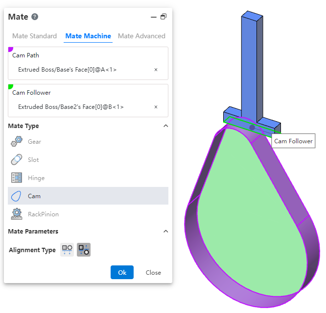
How to use:
After inserting the cam and follower parts, click the "Mate - Mechanical - Cam" command.
Select the cam groove, pick the element; successful selection will be highlighted in purple.
Select the cam follower, pick the element; successful selection will be highlighted in green.
In the "Alignment Type" section, choose the desired alignment method.
Click OK to generate the feature.
Note: The elements that can be picked for the cam groove and cam follower are points and faces. The profile sketch of the cam groove must form a closed loop, and there must be a tangent constraint between two connected lines. If features are added to the face used as the cam groove, breaking its continuity, the face cannot be picked as a cam groove element.
# RackPinion
This mate enables the gear part to rotate through the linear translation of the rack part.
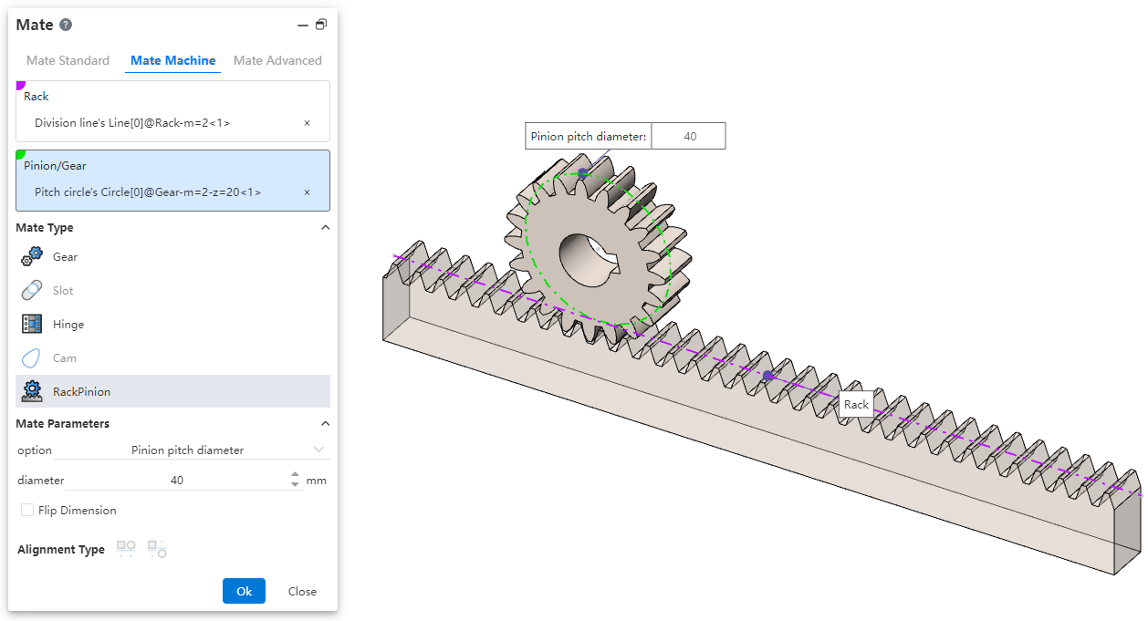
How to use:
After inserting the gear and rack parts, click the "Mate - Mechanical - Rack and Pinion" command.
Select the rack and pick the element (commonly the rack pitch line); successful selection will be highlighted in purple.
Select the pinion gear and pick the element (commonly the gear pitch circle); successful selection will be highlighted in green.
In the options, check either "Pinion Pitch Diameter" or "Rack Stroke/Revolution," and the system will automatically calculate the value. Additionally, users can manually set the parameters.
Decide whether to check "Reverse Dimension" based on your needs.
Click OK to generate the feature.
Note: Both rack and pinion support curves, cylindrical surfaces, and arc surfaces as pickable elements. This mating type can also be applied without drawing a gear, and can be achieved using linear edges, circular edges, and other features.
Dialog Box Control Instructions:
Pinion Pitch Diameter: The pitch circle diameter of the gear.
Rack Stroke/Revolution:
 × the pitch circle diameter of the meshing gear.
Reverse Dimension: By default, the gear rotates clockwise while the rack translates in the negative direction. When the "Reverse Dimension" option is checked, the gear still rotates clockwise, but the rack now translates in the positive direction.