# Revolved Surface
Select an open loop or closed loop sketch that rotates along the center line to generate surface features.
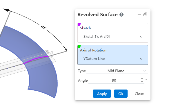
Click  to enter the Revolve surface command, whose interface is displayed as follows.
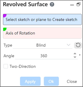
The functions of each control are as follows:
Sketch: Can be open loop or closed loop, must be a 2D sketch.
Note:
If the whole sketch is selected, only one open or closed loop can be included in the sketch;
If the sketch can contain more than one closed loop or open loop, select one of the lines or a set of continuous chains when selecting the sketch.
Axis of rotation: can be a 2D or 3D sketch, can be a center line, straight line, edge line, or two points, the axis of rotation cannot intersect the rotation Outlines.
If the sketch meets the following conditions, the reference line within the sketch is automatically picked up as the axis of rotation.
- The sketch has one or more contours that can be rotated, and in addition to the contours, there is only one guide line;
- The reference line is a straight line;
If the automatically picked rotation axis does not generate the rotation feature, such as the rotation axis intersects the contour, an error is reported;
Support selection of multiple types of elements as rotation axis:
- Straight line: sketch line, solid edge line or reference base line;
- Circular edge line: perpendicular to the plane where the circle is located, and the straight line past the center of the circle is used as the rotation axis;
- The axis of the cylinder serves as the axis of rotation;
- Two points: A straight line formed through two points serves as the axis of rotation.
Method: Given depth, formed to face, symmetrical on both sides.
Angle: The Angle at which the sketch is rotated along the datum plane determines the effect of the rotating surface.
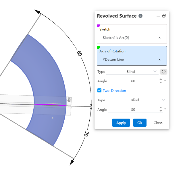
Direction 2: Take the datum plane of the sketch as the middle plane to rotate in two directions at the same time, there are two ways of rotation, choose different ways will have different corresponding parameters, and combine with the way in direction 1, preview the corresponding rotation effect. The methods are "given depth" and "Shape to face" respectively.
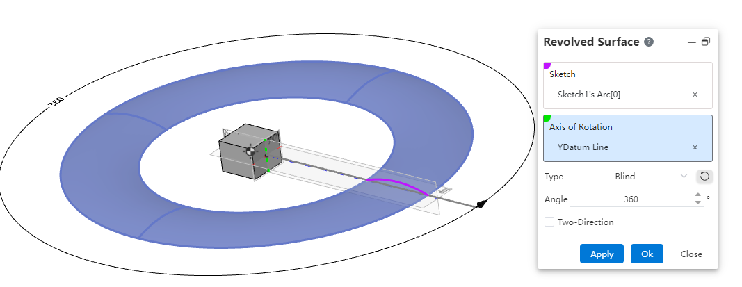
# Blind
Definition: The sketch rotates in a single direction to produce a surface.
Angle: Sets the angle at which the rotation is included.
Reverse: Reverses the direction of rotation.
Example:
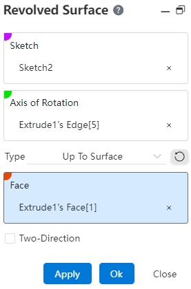
# Up To Face
Definition: Rotates from a sketch plane to a specified surface.
Plane\Surface: Select an existing surface for rotation cutoff that needs to fully envelop the rotation profile.
Example:
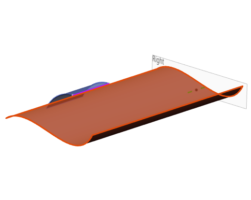
# Mid Plane
Definition: Generates a rotated surface from a sketch plane in a clockwise or counterclockwise direction.
Angle: Enter the total angle of the rotation.
Note:
Direction 1 is not available when both sides are symmetrical.
Example:
# Two-Direction
- Definition: After finishing direction 1, select direction 2 to define the sketch to rotate from the other direction.
There are two ways to stretch: given depth, shape to face.
Example: