# Swept Surface
Generate surface features by moving a scanned profile along a path.
# Instructions for Use
Click  to enter the Scan Surface command, whose interface is shown in the following figure.
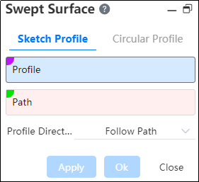
The functions of each control are as follows:
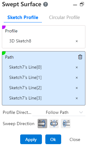
Scanning outline: can be edges, sketches, sketch lines, faces, etc. It can be open or closed loop, but it only supports selecting a set of scanned Outlines.
Scan path: Can be a curve, edge, sketch line, and so on, intersecting the contour plane but not in the same plane. It can be open-loop or closed-loop.
Contour Direction: Keeps the normal and changes with the path.
Note:
- Changes with the path: the section is always at the same Angle relative to the path;
- Keep normal: The cross-section is parallel to the starting section at the moment and has nothing to do with the path tangent vector.
Scan direction: direction 1, bi-directional, direction 2. When the scan profile is in the middle of the path (not the starting position), you can select a bidirectional scan.
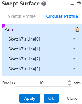
Circular Outline: When selected, the default circular outline (which defines the radius of the circle) scans along the selected path, and the contour direction changes with the path by default.
Note:
Scan contours, paths, and resulting surfaces cannot be self-intersecting.
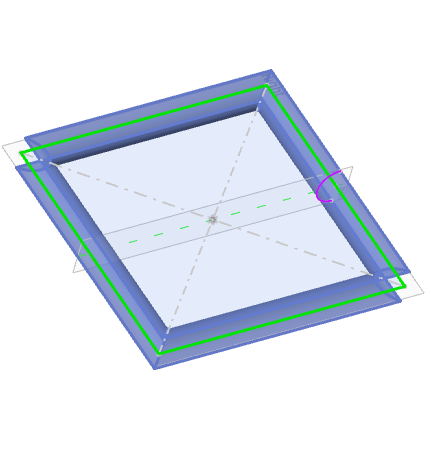
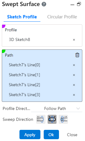
Example 1: The contour is non-circular, the contour direction is variable with the path, and the scanning direction is bidirectional, as shown in the following figure.
Example 2: The contour is non-circular, the contour direction is keep normal, and the scanning direction is bidirectional, as shown in the following figure.

Example 3: Select the Circular Outline command, as shown in the following image.
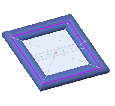
Click the OK button to complete the operation.