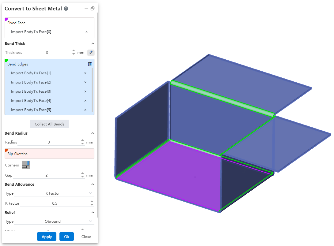
# Convert to Sheet Metal
Convert solid or curved entities to sheet metal parts.
- Click the button to bring up the Convert to sheet metal dialog box
 。
。
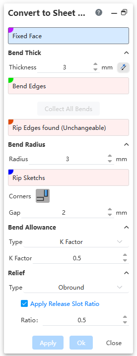
Dialog box control description:
1) Fixed face: Only one face of the entity can be selected as the fixed face, and the matrix flange or the face that has been converted to sheet metal cannot be selected. Only single option can be selected.
2) Thickness: Enter the sheet metal thickness value, the default direction is to thicken to the entity, click the reverse button to thicken to the entity.
3) Bending edge line: Select the edge line to bend, support multiple choices.
Allowing the selection of edges requires:
- Edge lines for fixed faces;
- The edge line of the surface connected to the fixed surface by bending;
- Edges that do not support picking up the cut.
4)Rip Edges found (Unchangeable): Displays the edges that the system automatically identifies as requiring a rip.
5) Radius: Enter the bending radius value.
6) Notch sketch: Select the straight sketch and separate the entire face along the selected sketch line.
7) Multiple sketches can be selected, each corresponding to one notch.
8) Edges and corners: Only clear butts are now supported.
9) Gap: The minimum gap between two adjacent sheet metal at the incision.
10) Bending Factor: Inherits from the base flange "Custom Bend Coefficient."
11) Relief Slot: Inherits from the edge flange "Custom Relief Slot."
- Automatic acquisition
Conversion to sheet metal supports automatic acquisition of all bends and automatic recognition of wall thickness.
How to use:
Click the "Convert to Sheet metal" command of the sheet metal module.
Select the imported or otherwise generated entity that you want to convert to sheet metal.
Set the fixed surface.
Click "Collect All Bends" and the system automatically fills in all available bends and automatically sets the corresponding wall thickness of the entity.
Click OK to finish the creation.