# Miter Flange
Used to add a series of sketch controlled flanges to one or more edges of the existing sheet metal. The adjacent flanges will automatically be cut/extended to meet the set gap value.
Click  the button to bring up the miter Flange dialog box.
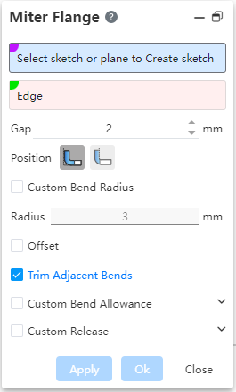
Dialog box control description:
- Select Sketch or Solid surface Draw Sketch: Select the sketch outline of the miter flange. An existing sketch can be selected, or a flat plane can be selected to go into the sketch.
One end point of the sketch line needs to coincide with the end point of the selected edge line.
The sketch consists of one continuous but not closed sketch line.
Edge line: Select the edge line that you want to generate the miter flange with support for multiple selections.
Radius: Control the radius of the rounded corner at the bend of the miter flange.
Gap: Control the gap value between flanges when selecting multiple edges.
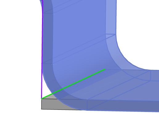
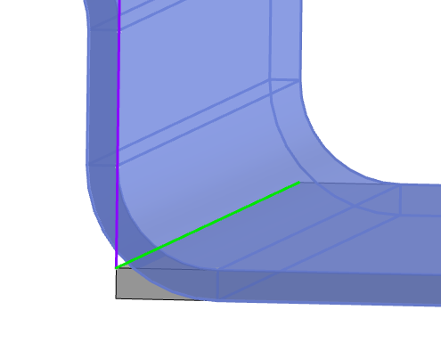
Position: Control the position between the miter flange and the existing flange, supporting "material inside, material outside". In the figure, the purple line is the selected sketch line, the green line is the selected edge line, and the gray entity is the original sheet metal, please note the position of the preview entity relative to the selected sketch line.
| Inside of the material | Outside of material |
|---|---|
 |  |
Offset: The offset value on both sides of the hem can be set after checking, so that the width of the miter flange is less than the length of the selected edge line.
Cut adjacent bends: After checked, automatically cut the bends that contact the side of the new flange.
Custom bending coefficient: the same base flange custom bending coefficient
Custom release slot: Check and set the size of the release slot, and the release slot is generated at the bend. Currently, two kinds of release slots are supported: rectangular round and rectangular. Generally used in conjunction with offset.
