# Base Flange
Convert a drawn sketch to a sheet metal entity.
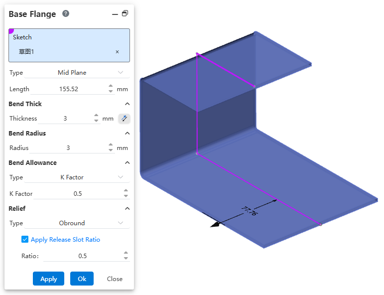
Click  the button to bring up the matrix Flange dialog box.Select the sketch, after the corresponding Settings, the effect is as follows.
Control description:
1.Select Sketch line: Select the sketch that you want to generate the base flange.
2.Method: Set the draw length in a way that currently supports "Blind,Mid Plane,Up to Vertex,Up to Surface".
3.Length: How far the sheet metal stretches from the datum of the selected sketch. The reverse button toggles the stretching direction.
4.Thickness: Sheet metal thickness. The reverse button toggles the thickening direction.
5.Bend radius: The inside radius of the rounded corner is automatically generated at the bend of the sketch.
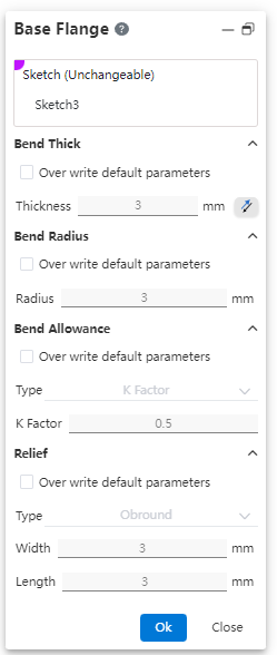
6.Bending parameters: Set the default bending parameters of the sheet metal corresponding to the matrix flange.
7.Bending parameter type: Select the bending coefficient type, currently supports K factor, bending coefficient, bending deduction, bending coefficient table.
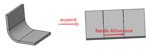
- Bending factor: the length of the sheet metal bend after it is developed
- Select this and enter the bending coefficient value in the Bending coefficient input box;
- The default bending coefficient value is 1, and the input range is ≥0;
- Length after bending expansion = bending coefficient;
- Bending deduction: the difference between the bending coefficient (length after bending unfolded) and the double external reversal (see figure below).
- Select this and enter the bending coefficient value in the Bending coefficient input box;
- The default bending coefficient value is 1,2 * External reversal ≥ The input range is ≥0;
- External reversal: Bend the outer surface of the sheet metal on both sides, extending in the tangential direction to the length of the virtual intersection;
- Length after bending unfolds =2* External reversals - bending deductions;
- Bending coefficient table: through sheet metal thickness and bending radius, Angle values, find the corresponding bending parameters in the given table, and apply to bending.
- K factor: The proportional relationship between the distance from the inner layer of sheet metal to the neutral layer and the thickness of sheet metal.
8.Release groove: Set the default style and parameters of the release groove for the sheet metal corresponding to the matrix flange.
Note:
1.The sketch can be a closed or open loop outline, and up to one layer of outline can be nested in the closed loop outline.

2.Sketch lines support spline curves.