# Dimension
Add horizontal, vertical, length, angle, and radius dimensions to sketch entities, and edit the added labels. Dimension editing is only valid in the No Command state or the Dimension Constraint command state.
Click  to turn on the Dimension Constraints command.
# Length Dimension
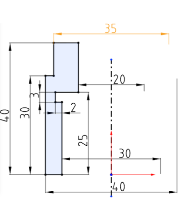
Label the length of a line or two points.
- Click to select a line or two points, drag the mouse to determine the position of the text, and click the left mouse button to end the label.

- Click the size value, activate the input box, Enter the size enter end, line and size update.


# Horizontal Dimension
Labels the horizontal distance of a line or two points.
- Click to select a line or two points, drag the mouse to determine the position of the text, and click the left mouse button to end the label.

- Click the size value, activate the input box, Enter the size enter end, line and size update.


# Vertical Dimension
Label the vertical distance between a line or two points.
- Click to select a line or two points, drag the mouse to determine the position of the text, and click the left mouse button to end the label.

- Click the size value to activate the edit box, Enter the number after enter the end, line and size update.


# Parallel Dimension
Labels the distance between two parallel lines.
- Click to select a line segment, click to select a second segment, drag the mouse to determine the position of the text, and click the left mouse button to end the label.

- Click the size value to activate the editing box, Enter the value after enter confirm, line and size update.


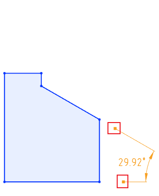
# Angle Dimension
Labels the angle between two non-parallel lines.
- Click to select a line segment, click to select a second segment, drag the mouse to determine the position of the text, and click the left mouse button to end the label.

- Click the size value to activate tht edit box,Enter the value and then enter to confirm,line and size update.


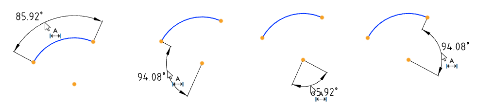
Mark the Angle between the three points.
- Click to pick up the three points in turn, drag the mouse to determine the place of "quadrant" and the text position, click the left mouse button to end the annotation.
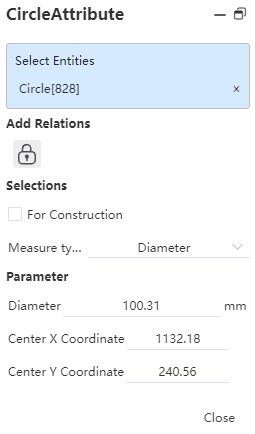
# Diameter/Radius Dimension
Dimensions the diameter of the circle or the radius value of the arc.
- Click to select a circle or arc, drag the mouse to determine the position of the text, and click the left mouse button to end the label.
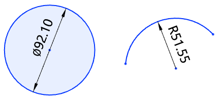
- Click the size value to activate the editing box, Enter the value after enter confirm, line and size update.


The default dimension diameter for the whole circle and the default dimension radius for the arc.
Click Circle/Arc to toggle diameter/radius in the pop-up Properties dialog box.
 |  |
| Click on the circle/arc line to toggle the diameter/radius | Click on the diameter/radius dimension line to toggle the radius/diameter |
After switching, the symbol corresponding to the value in the Dimension Properties - Value Panel updates accordingly.
End the command by the ESC key or by clicking Exit - Dimensioning
in the toolbar or in the right-click menu.
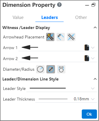
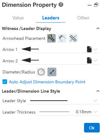
# Max/Min Dimension
When the selected element of the dimensioning has a circle or arc, it can be marked with its "Center, Max, Min" dimensions through the "Size Property - Lead" setting.
- When a circle or arc is present in the annotation element, the "Arc Condition" setting item appears in the "Dimension Properties - Leads" card of the annotation.
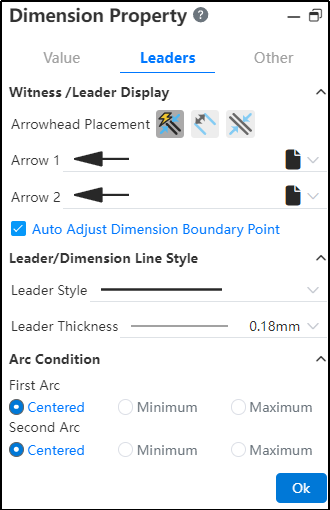
Arc one and arc two are displayed when there are two circles/arcs
Only arc 1 is displayed when there is only one circle/arc
When marking directly select the center of the circle, the corresponding arc condition setting item does not appear, and only select the circle edge line, its corresponding setting item is displayed
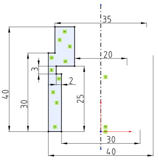
Example 1: Set the default annotation center size to the maximum size, as shown in the image below:
 |  |  |
- Using the Shift shortcut key allows quick toggling of circle/arc dimension annotations by clicking on different edge positions.
# Symmetrical Dimensioning
This operation helps you to label points, lines, circles, arcs to 2 times the size of the center line/reference line in the same sketch, and supports switching sizes.
1)Marking symmetrical dimensions
① Label two elements with the "size Constraint" command, one of which is the center line/guide line;
② If the size number is placed beyond the center line, it is marked as a symmetrical size;
2)Change the size type
After generating a symmetrical size, change the size to a radius size or a diameter (symmetrical) size through the properties panel for the size - Diameter/Radius.
# Value Dimension
In the sketch, you can label the distance or Angle between two elements as a 0 value, and the 0 value dimension can be modified again to other values.


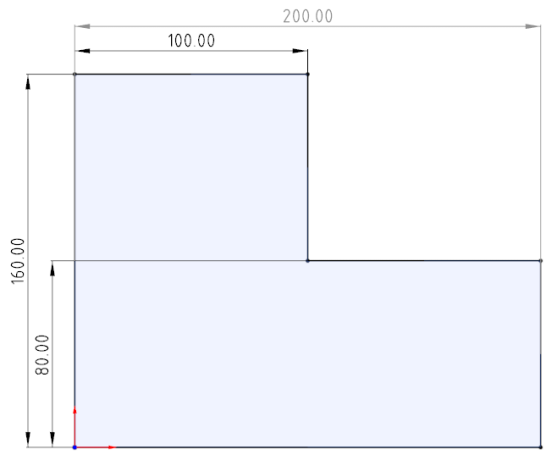
# Dimension Chain
Support for creating dimension chain annotations.
Creation steps:
1)Click the Size Chain command in the Size Constraints drop-down menu.
2)Left click to select the point or line as the dimensioned element of dimension chain 0 size.
3)Left click again after moving the mouse to place size 0.
4)Select the other elements you want to label to generate the dimension chain label.
5)Click the "Close" button to end the annotation.
Note 1:The driven/drive size can be set, and the drive size can be modified.
Note 2:See Drawing - Dimension Chain for other functions.
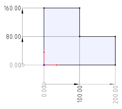
# Benchmark dimensions
Supports the creation of benchmark dimensions.
How to create:
1)Click the Base Size command in the Size Constraints drop-down box.
2)Pick up the elements you want to label in turn.
3)The first element is the base element, and the dimensions between subsequent elements and the first element are automatically labeled.
4)Press Esc to end the annotation.
Note 1:The driven/drive size can be set, and the drive size can be modified.
Note 2:See Drawing - Reference Size for other functions.
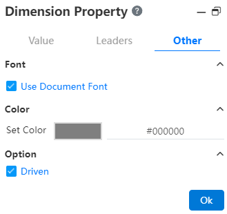
# Driven/Reference Dimension
You can create a driven size that only shows the size value but does not drive the model, with no constraint effect.
- To create the driven size:
- Method 1:In "System Settings - System Options - Sketch" select the overdefined size "Default is driven", the sketch will default to generate the driven size when the constraint size is added.
- Method 2:Select the driver size that has been marked, right-click "driven size", and click to change the size to driven size.
- Method 3:Select the size that has been marked, check "driven" in the "Other" item in the property panel, and the size will be changed into the driven size after confirmation.
- The slave size is switched to the driver size:
- Method 1:Select the driven size, right-click and select "Drive size", click to change the size to drive size.
- Method 2:Select the size that has been marked, uncheck "driven" in the "Other" item in the property panel, and the size will be changed to the driver size after confirmation.
- The driven size is displayed in gray by default, and the color can be modified by "System Settings - System options - Color - Size - Color of the driven size constraint".
- The driven size values are not modifiable and are automatically updated with the relevant constraints and drive size modifications.
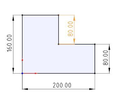
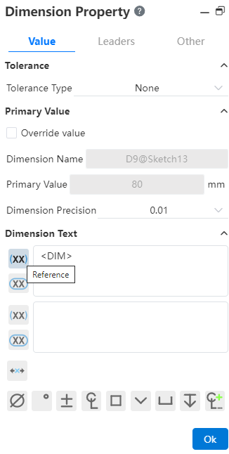
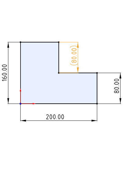
- Reference size:In order to better express the size used as a reference in the design, it can be identified by adding () to the size property box.
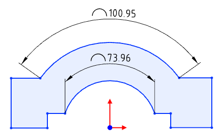
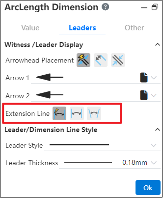
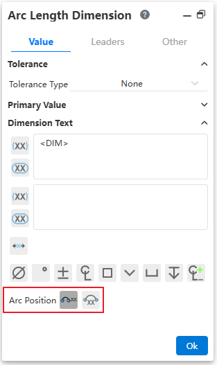
# Arc Dimension
Supports the creation of arc length annotations in sketches, and can be used as drive or driven dimensions.
Creation steps:
1) Click the [Label Arc Length]  command in the Size Constraints drop-down menu.
2)Click the left button to select the arc edge line to display the arc size preview.
3)Click the left button again after moving the mouse to place the arc dimensions.
4)Continue to select other arcs that you want to label for continuous labeling.
5)Click the "Close" button to end the annotation.
Note:Only arc lines can be marked.
Label style:The size boundary style can be modified as shown in the following figure.
Arc symbol position:The arc length marked arc symbol position can be modified as shown in the following picture.
Note:When the radius and arc length are set at the same time, if the arc length value set is too large, resulting in the arc Angle x exceeding 360°, the actual arc Angle T= X-n *360, n is the maximum integer value when T is positive.
# Boundary line Dimension

Default style:Size boundary parameters can be set in System Settings - Document Properties - Dimensions.
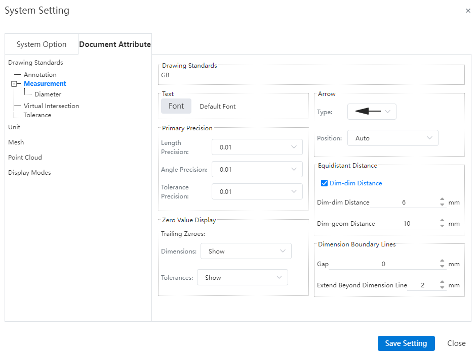
Gap:The gap between the size boundary line and the annotated element.
Beyond the size line length:The length of the size boundary line beyond the size line.
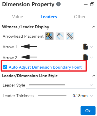
Manual adjustment:Select the Angle or length size, uncheck "Automatically adjust the size boundary end point" in the lead Tab of the size property dialog box, the square control mark is displayed at the end of the size boundary line, you can manually drag the control mark to adjust the boundary line. Check it again to restore the automatic adjustment of the boundary line.
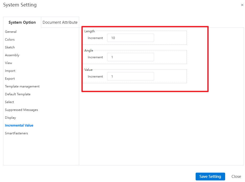
# Set The Size Increment Value
The user can customize the value to be added or subtracted when clicking on the value entry box arrow.

How to modify:
1)Viewport edit size (sketch size, feature size, etc.).
2)Click Reset Increment value and enter the increment value you want to set.
3)Enter and enter or click on an existing value to complete the setting.
4)Click the Add or subtract arrow in the Size Values dialog box to add or subtract with the set value.

Become the default value:Select and click a value to modify the default value set in system Settings, which takes effect for all sizes.
System Settings:Modify the default increment value in System Settings - System Options - Increment Value.
# Dimension Reverse Direction
Dimension support for reverse direction, allowing the relative positions of the annotated elements to be swapped.
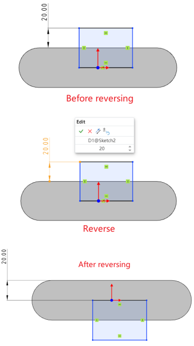
How to use 1:
1) Click the dimension you want to reverse.
2) Enter a negative value for the dimension, or click the "Reverse" button in the edit window.
3) Click the checkmark √ in the edit dialog box to swap the relative positions of the annotated elements.
How to use 2: Right-click the dimension and click the "Reverse" option.
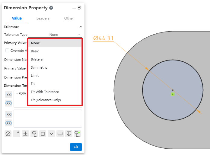
# Fit with Tolerance
Sketch dimensions support selecting multiple tolerance types. Refer to section Drawing-Dimensions for usage instructions.