# Extrude Boss/Base
Stretch the sketch outline in one or both directions to produce a solid.
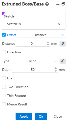
Click in the toolbar to open the Stretch Boss/Matrix command dialog box, whose command interface is shown below. 
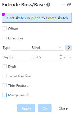
The first extrusion command in the part document does not contain a merge option. Pictured above.
Select a sketch or plane to sketch :
Pick up the sketch as a whole, and the system will stretch the outline within the entire sketch.
Pick up the sketch as a whole, and the system will stretch the outline within the entire sketch.
Pick up a plane/datum, enter the draw sketch state, draw sketch and exit, automatically fill the drawn sketch into the pick box.
Bias: After checking, the bias mode drop-down box appears. You can select the bias mode, and the stretching starts from the current sketch datum plane to the specified position. If necessary, point reverse.
Direction:After checking, the stretch direction can be customized, and the stretch direction is defaulted to the sketch normal direction when not checked.
Note:
The direction can be a sketch line, two points, a solid edge, or a reference reference line。
Method: There are a variety of ways, choose different ways will have different corresponding parameters, preview different stretching effects.
Draft:When selected, the draft slope is generated while stretching, and the draft angle can be adjusted by entering parameters or dragging the angle direction arrow.
Note:
Default outward draft, by tapping the reverse to inward draft.
Direction 2:After checking, stretch in two directions simultaneously with the sketch base surface as the benchmark, in two ways, namely“given depth”、“form to surface”,and direction 1 Make different combinations to preview different stretch effects.
Thin-wall feature: After checking, the outline of the sketch can be thickened and stretched to generate a thin-walled entity.
- Thin-wall feature is checked by default when the selected outline sketch has open loop line bars;
- When all the selected contour sketches are closed-loop lines, thin-wall features are not checked by default;
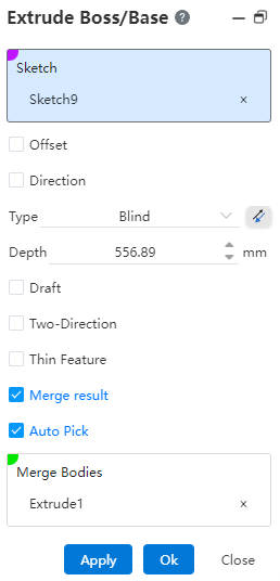
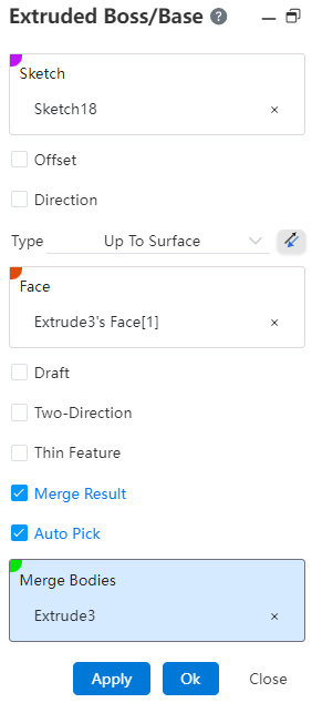
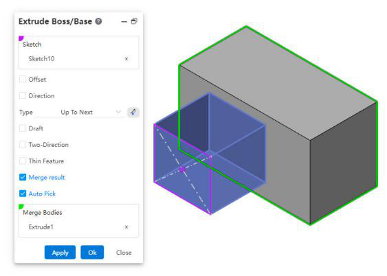
- Merge result: Used for stretching to merge with other entities into a single entity, if not selected, the feature will generate a separate body. If Merge and Auto pick is selected, the body in the auto pick document that can be merged with the current feature is filled into the pick box.
Note:
The premise of merging is that the merging body intersects the stretching body.
When weldments exist in the document, this option is not selected by default.
# Blind
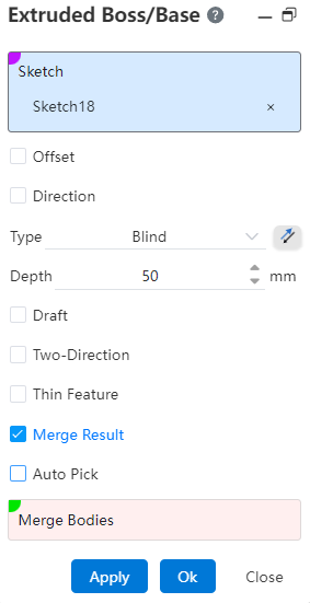
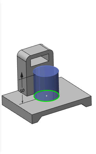
Depth:Stretches from the sketch plane in a positive direction, adjusting the depth of the stretch by entering parameters or dragging the stretch direction arrows. If necessary, point reverse.
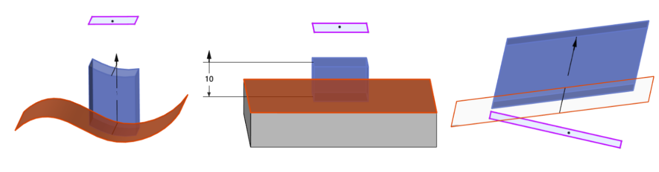
Example: Given the depth mode, the stretch effect is shown in the following figure.
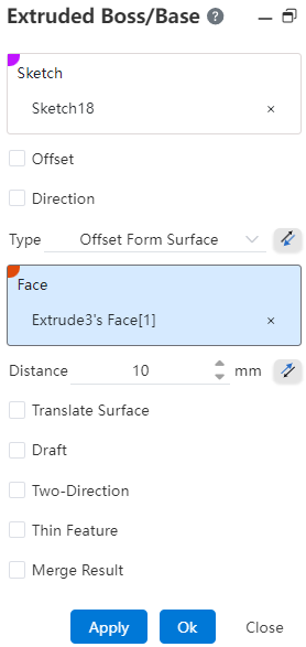
# Up To Surface
Face:Select a face to extend to. If necessary, point reverse.
Note:
Faces can be solid surfaces, planes, surfaces, or datums; The cylindrical or surface extent is larger than the sketch outline.
Example: In the shape-to-face mode, the stretching effect is shown in the following illustration.
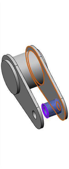
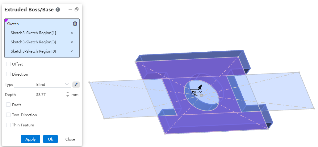
# Mid Plane
Depth:The sum of depths symmetrically stretched in both directions, using the sketch plane as a reference.
Example: Symmetrically on both sides, the stretching effect is shown in the following figure.
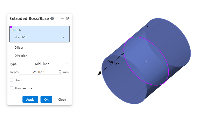
# Offset From Surface
Use this option if you need to maintain a certain gap or interference from a face.
Dialog box control description:
Method: You can select "distance from the specified surface", click the back button to change the stretching direction.
Face: Select the specified face.
Distance: Set the offset distance, support the input range [0.00001,10000000], support variables, equations. Click the reverse button in the back to modify the offset direction
Translation surface: Translation surface effect when checked, equidistant surface effect when unchecked.
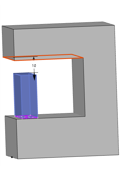
# Up To Vertex
Use this option when there is no surface at the point to which you want to stretch and you cannot select a specified depth.
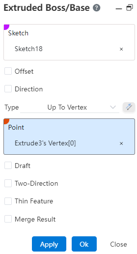
Dialog box control description:
Method: You can select Shape to Point.
Point: Specify the point to be shaped to. Pick up sketch point, sketch line endpoint, sketch line midpoint, center point, solid vertex, edge line midpoint, origin, coordinate origin, reference point. Lines, curves, arc lines, etc. of sketches and entities that are not closed (have endpoints), and the midpoint or end point nearest to the pickup position is taken when picking up a line.
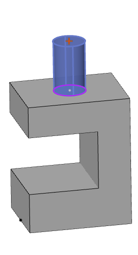
# Up To Next
The resulting stretch feature automatically terminates on the next plane outside the sketch and can meet the need to generate a specific stretch feature when it is difficult to judge the stretch distance.
Dialog box control description:
Method: You can select Shape to Next. (This mode occurs only when there is a next side that meets the condition)
Next side: The sketch is outside the solid outline and has a solid surface (either hidden or displayed) on which Boolean operations can be performed.
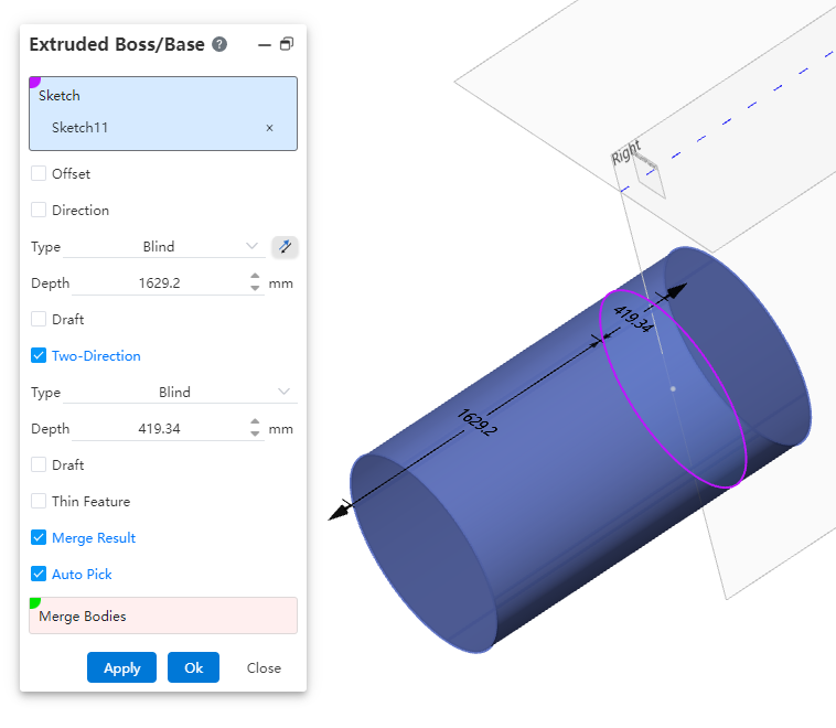
# Two-Direction
- After checking,stretch in the other direction with the sketch plane as the datum.
Note:
When the tension method is selected for symmetry on both sides, there is no direction 2 option.
- The stretching methods are“given depth”、“form to surface”,and the operation is the same as above.
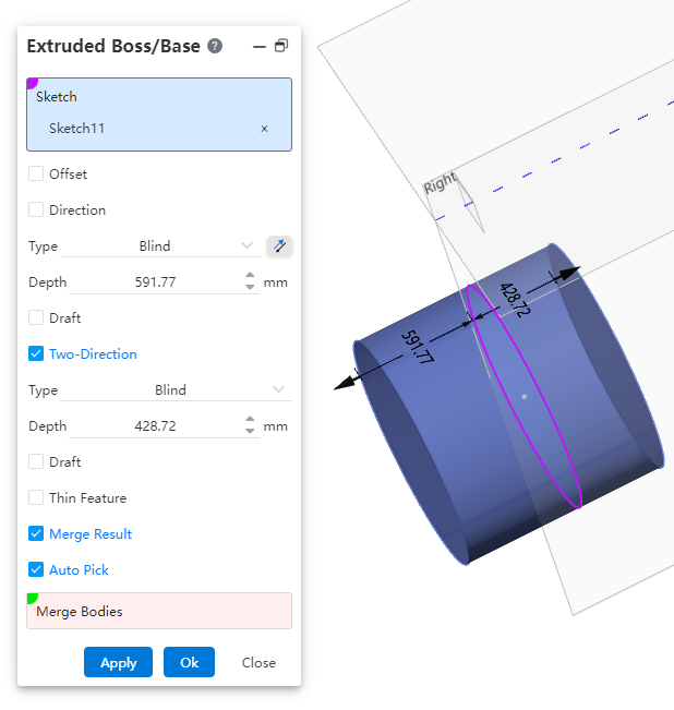
Example: After setting the relevant parameters, the direction 2 is stretched for a given depth as shown in the following figure.
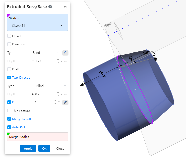
# Draft
After ticking the mold,enter the draft angle. If necessary, point reverse.
Example 1: The no draft effect is shown in the following figure.
Example 2: The inward draft effect is shown in the following figure.
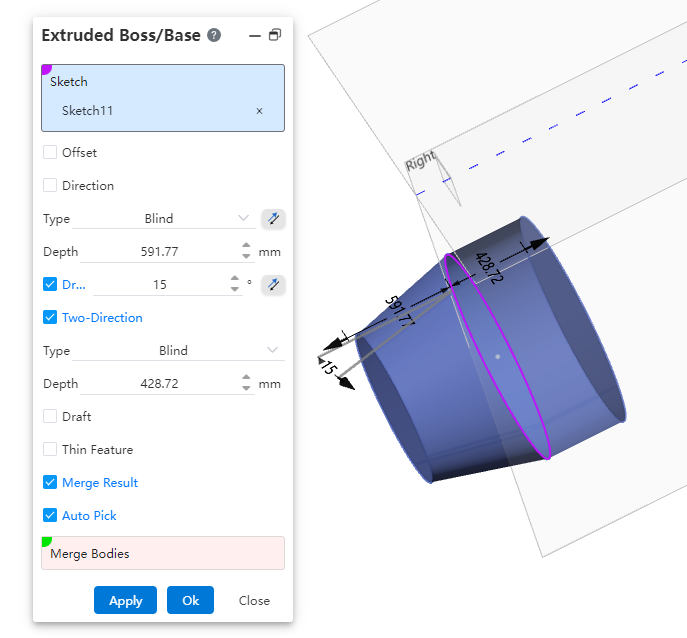
Example 3: The outward draft effect is shown in the following figure.
# Offset
After checking, the Bias mode drop-down box appears, you can select the bias mode, stretching from the current sketch datum offset to the specified position. If necessary, point reverse.
- Bias mode
(1) Distance: Enter the distance in the open Distance Modification dialog box and the stretch starts on a datum equidistant from the current sketch datum.
(2) From Surface/surface/datum: Pick up the starting surface in the open Starting surface pick box and the stretch is created from the selected surface.
【 Surface range: The plane and base surface have an infinite range of action, and the surface's range of action is not expandable 】
Example: After setting the relevant parameters, the bias-distance effect is shown below.
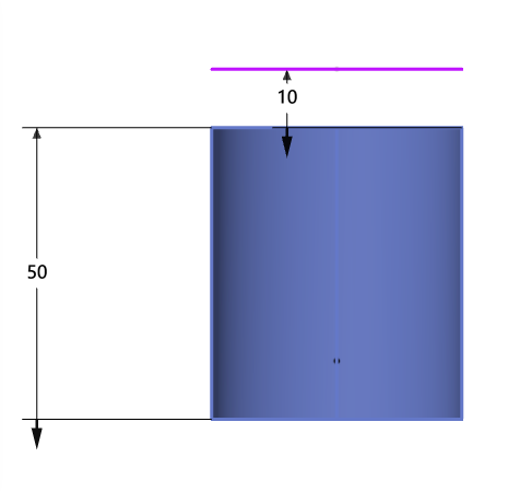
After picking up the bias surface, the bias-distance effect from the surface/surface/datum is shown below.
# Thin Feature
After checking thin features, the Settings shown in the picture appear.
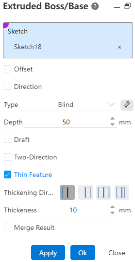
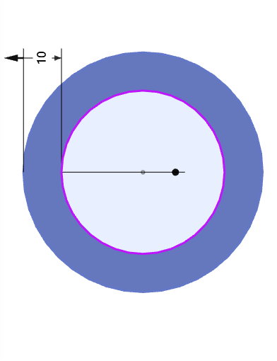
The thickening direction is "direction 1", "Direction 2", "bilateral symmetry", "bilateral asymmetry", and the default thickness parameter is 10mm; The effect of different thickening directions is as follows:
| Direction 1 | Direction 2 |
|---|---|
 |  |
| Bilateral symmetry | Asymmetry on both sides |
 |  |
# Reverse lateral excision
The Extruded Boss feature supports extruding multiple non-intersecting profiles in a single operation. Based on this capability, you can directly extrude sketch text without first performing the "Explode Text" operation.
# Stretch/Rotate a selected local area
Support stretching/rotating a selected local area of a sketch.
How to use:
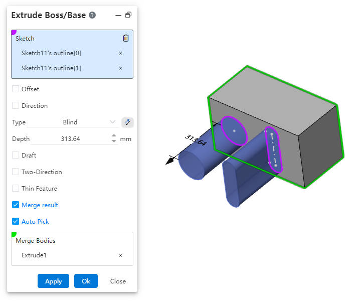
Take the "Extrude Boss/Base" command as an example and open it.
Click on the sketch from which you want to select a local area.
Click on the local region within the sketch that you want to extrude; multiple selections are supported.
Set other parameters, click "OK," and complete the creation of the extrusion feature.
Note:
The commands "Extrude Boss/Base," "Extrude Cut," "Revolve Boss/Base," and "Revolve Cut" all now support local area selection.
Before selecting a local region, click once on the sketch containing the desired area. As you move the mouse over the sketch area in the viewport, the region will be highlighted when it becomes selectable.
# Up To Body
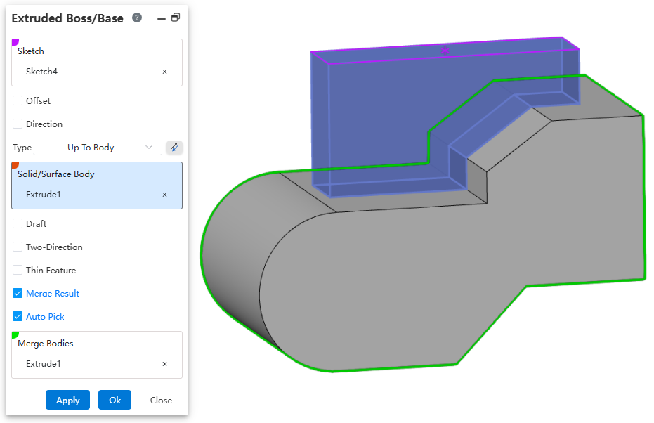
Usage:
Open the Extruded Boss/Base command.
Select the sketch.
Set the option to "Up To Body".
Select the target body/surface.
Click OK to complete the creation.
← Solid Extruded Cut →