
# Assembly
# Mirror Components
Mirror Components now supports pre-selecting a reference plane as the mirror plane, improving ease of use.
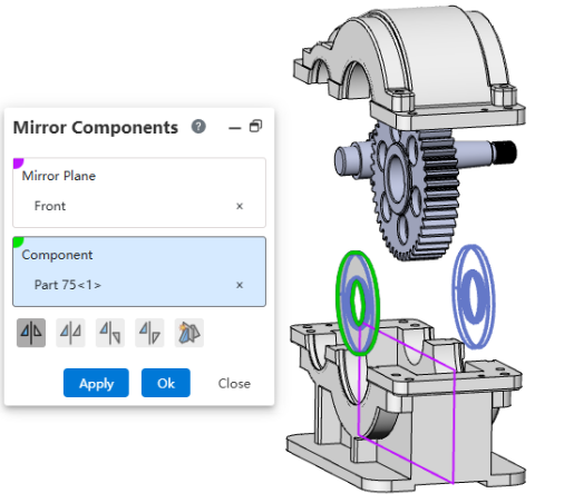
Usage:
- Pick a reference plane.
- Open the "Mirror Components" command. The pre-selected reference plane will be populated as the mirror plane.
- Select the instances to mirror and the mirror method.
- Click "Apply/OK" to complete the mirroring.
# Quick Mate
After selecting multiple elements in the viewport, the Quick Mate tool that appears supports more mate types.
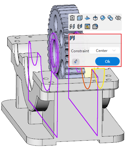
Usage:
- Hold the Ctrl key and select multiple elements in the viewport to which you want to add mates.
- Release the Ctrl key. The Quick Mate tool appears near the cursor.
- Click a mate type in the Quick Mate tool. The configurable parameters for that mate are displayed.
- Set the mate parameters.
- Click Confirm to complete the mate addition.
Mate types supported by the Quick Mate tool:
- Standard Mates: Coincident, Parallel, Tangent, Concentric, Perpendicular, Distance, Angle.
- Mechanical Mates: Slot, Cam.
- Advanced Mates: Profile Center, Symmetric, Width, Limit Distance, Limit Angle.
# Assembly Features
# Chamfer
The Assembly Features now include the Chamfer command, allowing you to create chamfer features within an assembly.
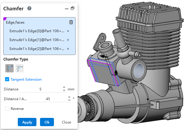
Usage:
- Open the "Chamfer" command in the assembly document.
- Pick the edge(s) or face(s) to chamfer.
- Set the chamfer type, distance, and other parameters.
- Click OK to complete the feature creation.
# Fillet
The Assembly Features now include the Fillet command, allowing you to create fillet features within an assembly.
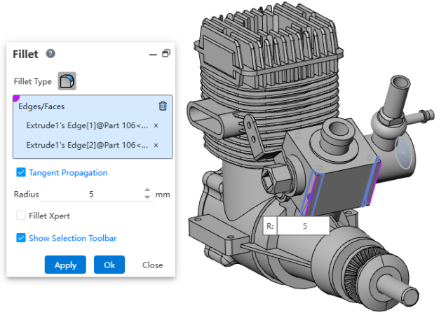
Usage:
- Open the "Fillet" command in the assembly document.
- Pick the edge(s) or face(s) to fillet.
- Set the radius and other parameters.
- Click OK to complete the feature creation.
# Hole Wizard
The Assembly Features now include the Hole Wizard command, allowing you to create holes on components within an assembly.
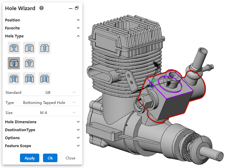
Usage:
- Open the "Hole Wizard" command in the assembly document.
- Set the hole placement position.
- Set the hole type, specifications, and other parameters.
- In the "Feature Scope" section, select the components on which to create the holes.
- Click OK to complete the feature creation.
# Linear Pattern
The Assembly Features now include the Linear Pattern command, allowing you to create patterns of assembly features.
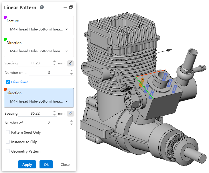
Usage:
- First, ensure that the features to be patterned are assembly features created within the assembly.
- Open the "Linear Pattern" command.
- Pick the assembly features to pattern.
- Set the direction, spacing, and other parameters.
- Click OK to complete the pattern creation.
# Circular Pattern
The Assembly Features now include the Circular Pattern command, allowing you to create patterns of assembly features.
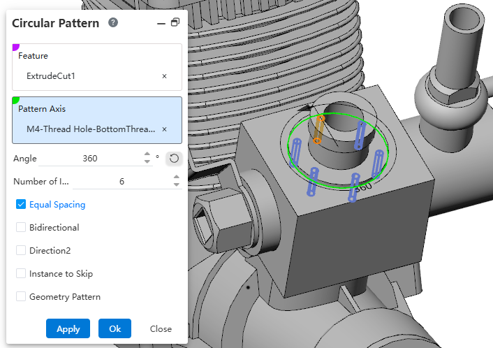
Usage:
- First, ensure that the features to be patterned are assembly features created within the assembly.
- Open the "Circular Pattern" command.
- Pick the assembly features to pattern.
- Set the direction, spacing, and other parameters.
- Click OK to complete the pattern creation.
Note 1: Assembly features are displayed in the Assembly Features panel after creation and do not affect the content of the components themselves.
Note 2: Right-click an assembly feature to perform the following operations: Edit Feature, Suppress, Zoom to Fit, Feature Dependency, Delete, Rename, Invert Selection.
Note 3: For descriptions of the dialog controls of each assembly feature, please refer to the part features.
← Features Sheet Metal →