# Welcome to CrownCAD 2025 R1
CrownCAD 2025 R1, widely absorb the most real feedback from users, to maximize the realization of customer needs. In terms of usability, it is committed to improving customer experience; In terms of functionality, continuously adding commands that customers urgently need can help you quickly complete product design and development work.
Major enhancements:
| Sketches | Angle annotation, support to select three points to mark the Angle. |
| Equation curve, support input variables, to achieve more perfect and intelligent parametric modeling. | |
| Parts and Features | Stretch boss, stretch cut command optimization, automatically adjust the Angle of view when facing the sketch drawing, support the forming to the next side, support from the surface/surface/datum start drawing. |
| The datum tangent type supports reverse, adding two line types to create a datum through two straight lines. | |
| Scan excision feature support for array/mirroring as feature source. | |
| Added Union trim command to make multiple entities trim each other and specify blocks to keep or remove to form new entitie | |
| New ellipsoid command for quick creation of ellipsoids. | |
| New base line added Angle bisectors, points and planes, points and lines types for more flexible base line creation. | |
| New bending command for bending or twisting solid/curved surfaces. | |
| Added the Deformation command, which supports the deformation of the entity/surface according to the specified way. | |
| Added Entity blending command to quickly create intersecting sections of stretched sections of two sketches. | |
| Added the Scale scaling command to support overall scaling geometry. | |
| Added the overlay command, which supports the coating of sketch patterns onto solid surfaces. | |
| New curved surface flattening command, support to expand the surface to a plane. | |
| Added parallel curve command, support to offset the line on the surface. | |
| Assemble | |
| New document path feature to support finding parts paths. | |
| New documents generated by the mirror in the opposite direction can be associated with the source document. | |
| Right-click and long in the viewport to drag the rotatable part. | |
| Variable management support fit size, support control instances and fit suppression state. | |
| Drawings | Section view supports drag and drop to modify the section position. |
| Base adds text edit box, support to add custom text around the base symbol. | |
| Part serial number can be selected by the serial number, the material list order will be updated. | |
| Note editing display border and control label, support setting alignment direction, easy to control the position of note text. | |
| Drawing format automatic border to add more parameters, support the generation of custom picture frame. | |
| Angle annotation, you can select three points to annotate the Angle. | |
| View supports reading 3D PMI annotation. | |
| Supports bulk export of PDF files. | |
| Support box select the same type of elements, batch edit. | |
| Evaluation tools | Added Compare document, which allows you to compare document properties. |
| Interference check command supports the detection of entities in parts. | |
| Sheet metal | Edge flange re-edit support Re-edit edge, support reverse. |
| Conversion to sheet metal supports automatic acquisition of all bends and automatic recognition of wall thickness. | |
| Sheet metal features support modification of size and suppression of state in variable management. | |
| Weldment | Weldment features support modification of size and suppression of state in variable management. |
| Cables | |
| New Edit wire command to edit properties of existing wires, etc. | |
| New Insert electrical parts command, you can freely insert the required electrical parts. | |
| Added the Insert cable command, which allows you to freely draw paths and generate cables. | |
| Added the Statistics Table command, which allows you to view the statistics of the current cable document through many types of tables. | |
| Quick Design | Support rapid creation of cylindrical gears, bevel gears. |
| Direct editing | New Direct editing module that provides commands for editing models directly. |
| Point Cloud | Added import point cloud function, support *.xyz; *.asc; *.ply; *.pcd four formats. |
| New positioning function, you can move, rotate and other positioning operations. | |
| Added the Delete redundant points function, which can delete redundant points in the point cloud. | |
| New denoising function, which can remove discrete points with large errors. | |
| New simplification function to improve model processing efficiency and optimize data quality. | |
| New grid function, which can turn point cloud into grid. | |
| Data conversion | |
| The Obj model supports textured conversions. | |
| Added support for dgn format models. | |
| Synergy | Set ownership of team projects/documents when dissolving a team. |
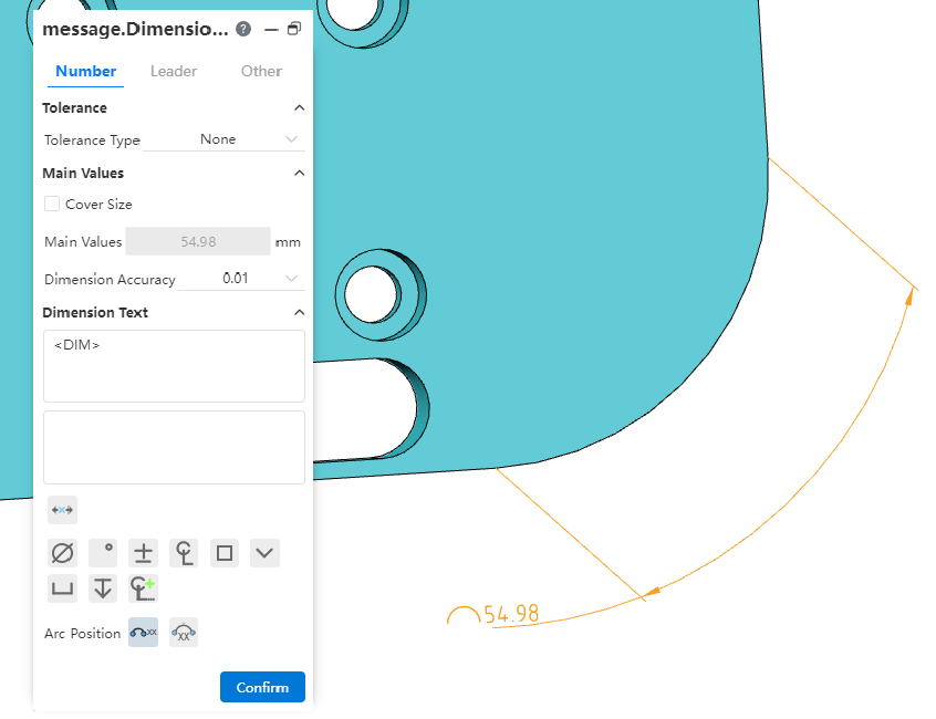
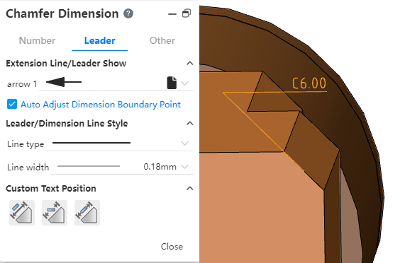
| MBD | Added dimension chain, chamfer dimension, reference dimension, arc length dimension annotation command to generate more annotation types. |
| Can be annotated element type expansion, support point, line, surface. | |
| Benchmark adds text editing box, support to add custom text around the benchmark symbol. | |
| Tools | New layers in parts, assembly, organization and management of the visibility and selectivity of objects in the document. |
| When sketching, the mouse cursor displays the corresponding icon according to the current command. | |
| Add the Save document command. | |
| Added packaging, support associated documents packaging into new projects. | |
| Applications | Double click "Materials" in the features panel to quickly open the Material library. |
| Click on the standard part that has been inserted in the assembly to quickly modify the specifications in the pop-up menu. | |
| Render | Transparent rendering supports the selection of other elements that are obscured by the transparent surface. |
| Solids/surfaces can be displayed in isolation in parts. | |
| Project documentation | New transfer ownership function, support transfer of project, document ownership. |
# Sketches
# Angle notes
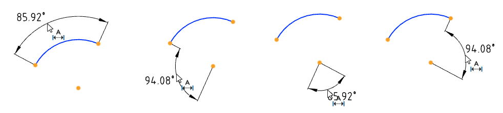
Select three points to quickly generate Angle annotations. When annotating angles between points, there is no need to create two guides first, which improves sketch annotation efficiency. At the same time, the Angle can be annotated in different quadrants to meet your custom annotation needs.

Usage method:
1) Click the "Size Constraints" command.
2) Pick up three points in turn.
3) After picking the third point, the Angle annotation preview is displayed.
4) Move the mouse to select the position of the Angle annotation, noting that it can be placed in different "quadrants".
5) Click the left mouse button to place the Angle dimensions.
6) Modify the value in the "Edit" window that pops up and click the "√" button to end the creation.
Instructions:
The three points selected are the two ends of the same arc and the center of the circle, and the vertex of the Angle is the center of the circle.
The three points chosen are not the two ends and the center of the same arc, and the vertex of the Angle is the first point in the picking order.
# Equation curve
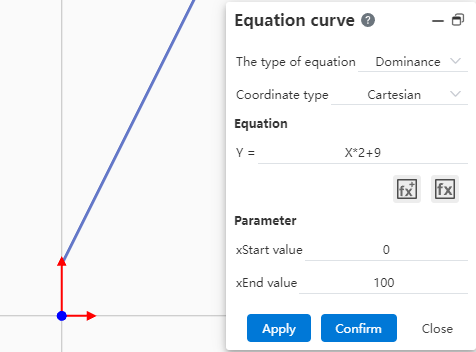
Equation curves support input variables. When the features related to variables change, the variable parameters in the equation curve can be automatically updated to achieve a more complete and intelligent parametric design.
Usage:
1) Use the "Variable Management" function to create the desired variables.
2) Go to the sketch and click on the "Equation Curve" command.
3) Enter the variable name into the input field and the available variables will be displayed in the drop down box.
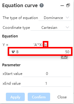
4) Mouse click on the variable in the drop-down box to reference this variable in that input box.
5) Enter the other parameter content.
6) Click OK to finish creating the equation curve.
7) When the value of this variable is modified, the equation curve will be automatically updated.
# Parts and Features
# Automatic adjustment of viewing Angle
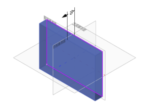
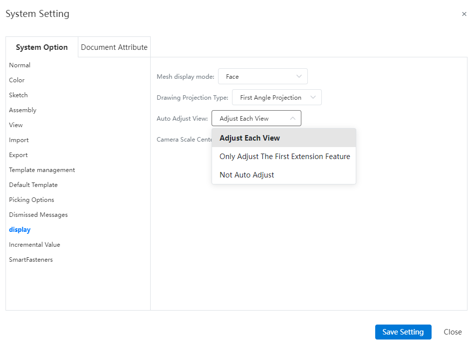
Automatic adjustment of stretch boss/excision generated viewing Angle. After the drawing of the sketch is completed, the Angle of view is facing the sketch, and the drawing length cannot be intuitively seen. Automatic adjustment of the Angle of view Supports automatic rotation of the Angle of view in the scene, so that you can observe and adjust the length of the stretch. The effective condition of "Automatically adjust the Angle of view when creating features" can be set in "System Settings - Display" to meet your adjustment Angle requirements.
Use method:
1) Turn on system Settings and click "Display".
2) Click the "Adjust View Automatically" drop down box and select the effect condition "Adjust every feature".
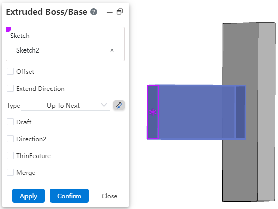
3) Click to select the sketch that you want to stretch the boss/cut.
4) Click to open the "Stretch boss/base"/" Stretch Cut "command.
5) The Angle of view is automatically adjusted to make the bar face 45° to the lower left corner, which makes it easy to drag the bar to change the length.
Description:
Select "Adjust every feature" in the Settings, then the Angle of view will be automatically adjusted every time the stretch feature is generated in the file.
Select "Only the first stretch Feature Adjust" in Settings to automatically adjust the viewing Angle only for the first stretch feature after the file is created.
Select "Do not automatically adjust" in Settings, and the stretch feature view created in the file will face the sketch.
# Stretch boss, stretch cut
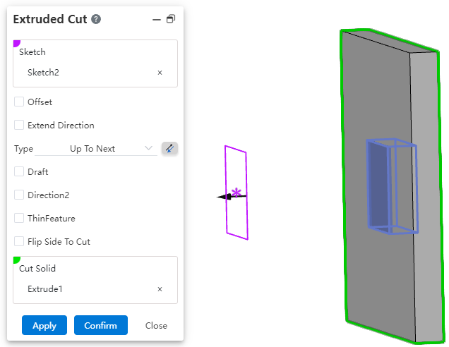
# Shape to next side
Add stretch boss/cut way in "shape to next side". The resulting stretch feature automatically terminates on the next plane outside the sketch, which can meet your need to generate a specific stretch feature when it is difficult to judge the stretch distance.
How to use:
1) Click the "Stretch boss/base" or "stretch Cut" command.
2) Method select "Shape to Next Side".
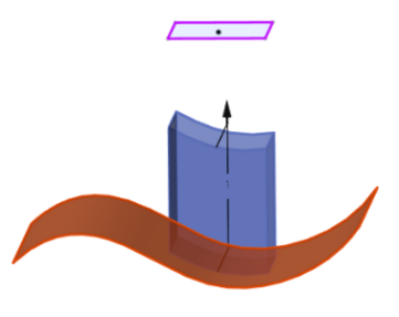
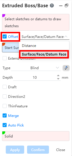
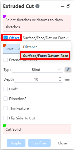
# Support stretching from the surface/surface/datum
Add stretch boss/cut bias type "from surface/surface/datum". Support for creating stretch features from the selected surface.

Stretch boss/matrix
Stretch excision
To use:
1) Click the "Stretch boss/base" or "stretch Cut" command.
2) Check "Offset".
3) In the "Bias" drop down box click to select "From Surface/surface/datum".
4) Pick up the stretch sketch and the starting surface.
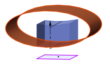
Instructions:
- If the contour sketch has multiple projections on the selected curve surface, the stretch feature is generated from the projection closer to the sketch (take the stretch boss as an example).
# Reference Plane
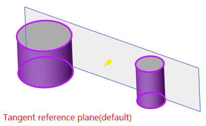
# Tangential
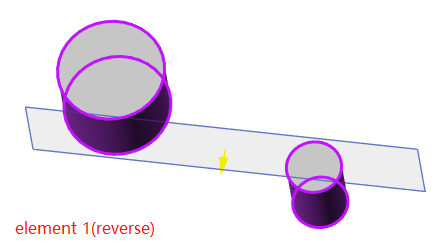
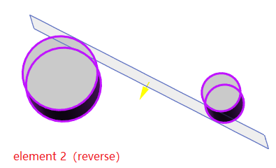
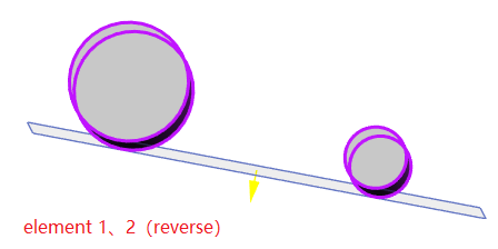
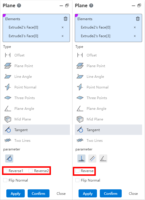
Tangential type datum adds reverse control function. When creating a tangential datum, if the element has more than one tangential direction, you can switch the direction by checking the reverse option. Meet the scenario where you need to create the reverse function to control the datum plane of the tangential effect.
How to use:
1) Click to open the Datum command.
2) Select Type of operation - Tangent.
3) Pick up the element that creates the tangent type datum.
4) Check "Reverse"/" Reverse 1 "/" Reverse 2 "as needed to switch the tangential effect.
5) Click Apply/OK to complete the creation.
Instructions:
- When both elements can be reversed, the "reverse 1, reverse 2" two options are displayed to control the reverse of elements 1 and 2 respectively. When only one element can be reversed, only one "reverse" option is displayed, and the reversible element is reversed after being checked.
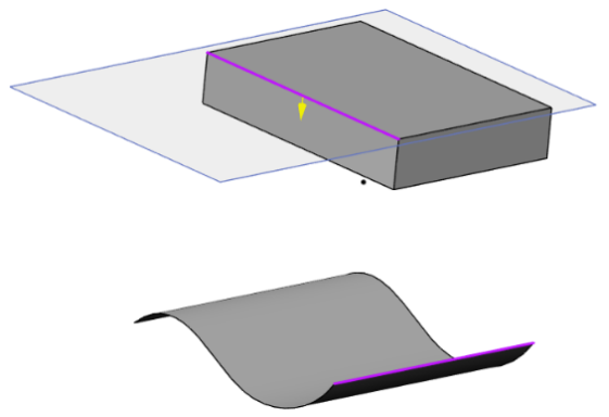
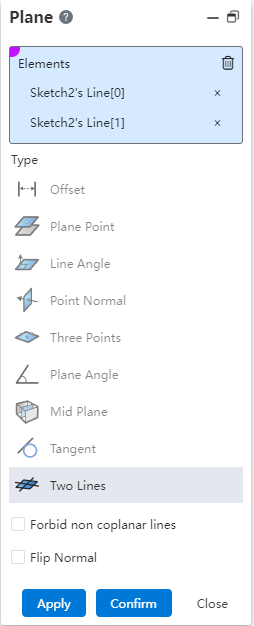
# Two Straight Lines
Added more types to generate datum - two straight lines. Increase the type of datum generation to meet the scenario of using two straight line elements to quickly generate datum, without additional auxiliary elements such as sketching, improve product flexibility.
Usage method:
1) Click to open the Datum command.
2) Select Operation Type - Two lines.
3) Pick up two straight line elements.
4) You can check "Do not allow non-coplanar curves" to limit the range of lines that can be picked up.
5) Click Apply/OK to complete the creation.
Instructions:
Generating effect: The datum plane overlaps with the first straight line and is parallel to the second straight line.
Pick the element first and then select the operation type/Select the operation type first and then pick the element.
If "Do not allow non-coplanar curves" is checked, only two lines that are coplanar can be picked up.
# Reference Lines
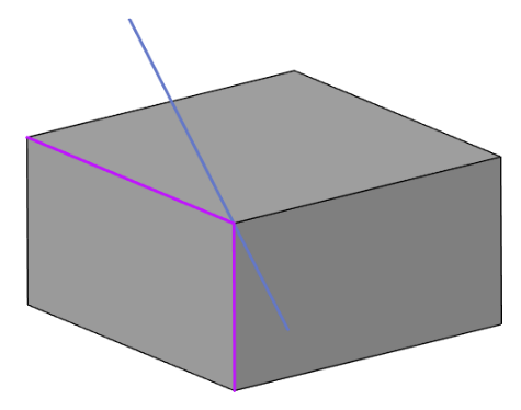
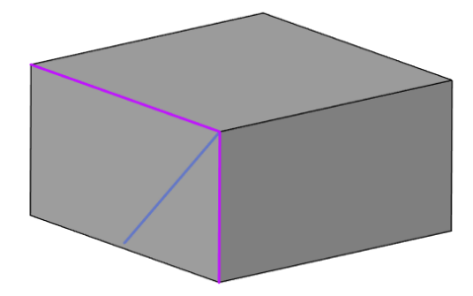
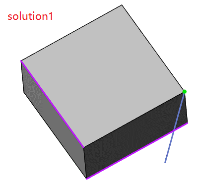
# Angular bisector
New base line for Angle bisector type to meet your need to quickly generate base line for Angle bisector type. The process of creating this type of reference line does not need to draw additional sketches, etc., improve product flexibility.
How to use:
1) Click on the Start Baseline command.
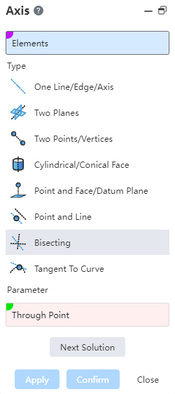
2) Select Operation Type - Corner Bisector Line
3) Pick up elements: Two lines that are not collinear.
4) Pick up the passing point of the reference line.
5) Click "Next Solution" to switch the generated effect of the Angle bisector.
6) Click Apply/OK to complete the creation of the baseline at the pass point.
Instructions:
- For two intersecting lines, through the point pick up box is not required, if not pick up through the point, the default at the intersection of the two lines to generate a reference line; If the pass point is picked up, the Angle bisector is translated so that the starting point coincides with the selected point.
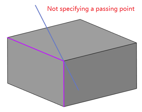
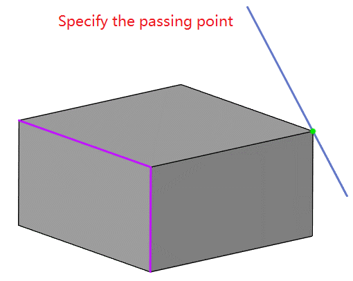
- For disjoint lines, the pass point pickup box is required. The effect is to translate two imaginary reference lines to the selected point, and the resulting Angle bisector is used as the reference line.
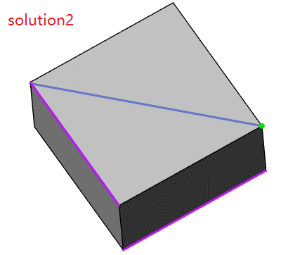
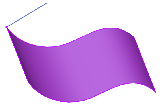
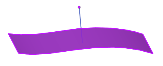
# Points and Planes
Add reference lines for point and surface types to quickly generate reference lines by selecting any face and any point in different scenes. No need to draw additional sketches, etc., to improve product flexibility.
How to use:
1) Click on the Start Baseline command.
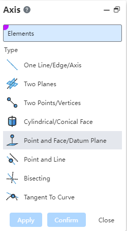
2) Select operation type - point and surface.
3) Pick up elements: Any face and any point.
4) Click Apply/OK to finish the creation.
Instructions:
Generate effect: Through the selected point A, generate the selected surface normal direction of the reference line.
The point can be a point on the non-pick face.
# Points and lines
Add reference lines for point and line types so that arbitrary faces and lines can be selected in different scenes to quickly generate reference lines. No need to draw additional sketches, etc., to improve product flexibility.

How to use:
1) Click on the Start Baseline command.

2) Select operation type - point and line.
3) Pick up elements: any points and lines.
4) Click Apply/OK to finish the creation.
Instructions:
- Generating effect: The base line position passes through point A, and the direction is parallel to line B.
# Array/mirror image
Add array/mirror feature support for selected features. Open the function of array/mirror on the scan excision feature. You can select the scan excision feature as the array source to meet the needs of more design scenarios and improve product flexibility. (The array effect diagram only takes linear array as an example, and other array modes are supported).
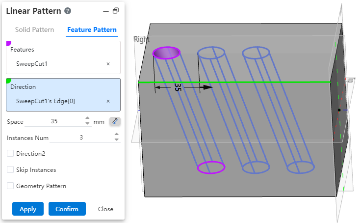
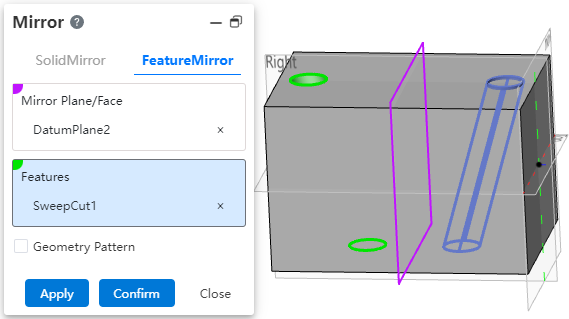
Usage:
1) Click the Open Array/Mirror command.
2) Pick up the scan excision feature that requires the array/image.
3) Pick up the array direction/mirror face.
4) Click Apply/OK to finish the creation.
# Combine Pruning
Added the joint pruning feature, through which you can achieve the removal of unwanted parts in multiple intersecting entities to generate the desired one entity. With the joint pruning function, rapid pruning can be achieved without multiple operations using functions such as Boolean operation or segmentation, simplifying modeling steps and improving design efficiency.
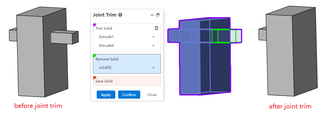
Usage method:
1) Click to open the Joint Trim command.
2) Pick up at least two entities to trim.
3) Pick up the blocks you want to remove/keep.
4) Click Apply/OK to finish trimming.

Instructions:
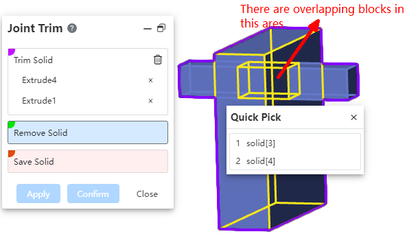
Multiple entities are allowed to be selected, but only blocks on two of them can be picked up as blocks to be removed/retained.
The blocks to remove/keep are not required and multiple selections are supported, but at least one of them is selected.
If the block to be removed is specified first, all blocks except the selected block to be removed are preserved; If a reserved block is specified first, all blocks other than the selected reserved block are deleted.
When there are multiple blocks that coincide over the mouse position, stay for a period of time and click to display the quick pick up dialog box. You can specify which block to pick up. When the mouse points to the blocks in the quick pick up dialog box, the corresponding blocks in the viewport should be highlighted for easy differentiation.
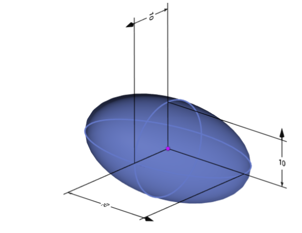
# Ellipsoids
An entity for quickly creating an ellipsoid shape. When it is necessary to create an ellipsoidal entity, there is no need to carry out multi-step operations such as drawing sketch outline, preparing the rotation axis, rotating the boss, etc., providing you with commands to directly create the ellipsoid to simplify the creation step and improve the modeling efficiency.
Usage method:
1) Click the Open Ellipsoid command.
2) Pick up center point/Set center point coordinates.
3) Pick axis 1 direction/Axis 2 direction.
4) Set Axis 1 length/Axis 2 length/Axis 3 length.
5) Click Apply/OK to complete the creation.
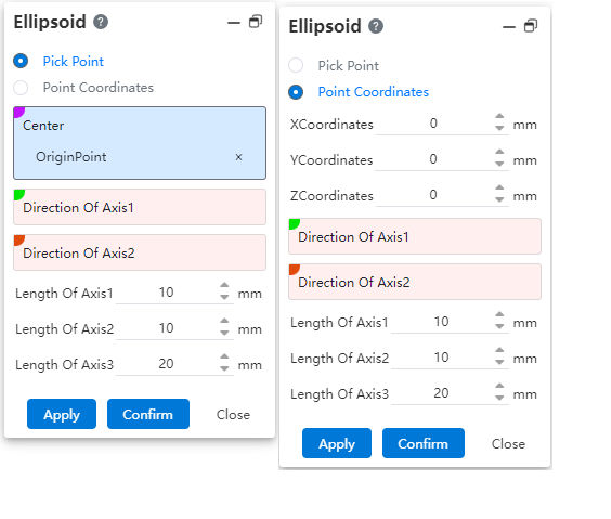
Instructions:
The ellipsoid can be created normally by picking up the point/point coordinates either way.
Axis 1 direction/Axis 2 direction is not required. When axis 1 direction is not picked up, the X direction is taken as the direction of axis 1 by default; When axis 2 direction is not picked up, the projection of the Y or Z direction on the vertical face of axis 1 direction is taken as the axis 2 direction by default.
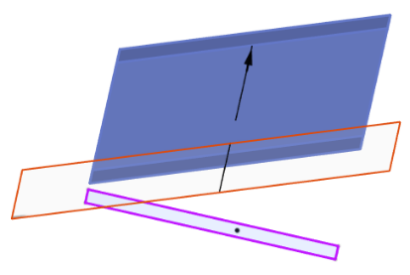
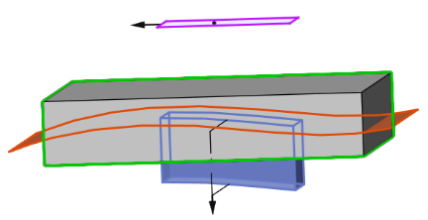
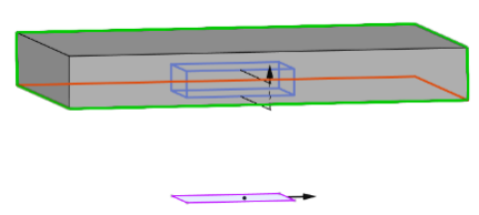
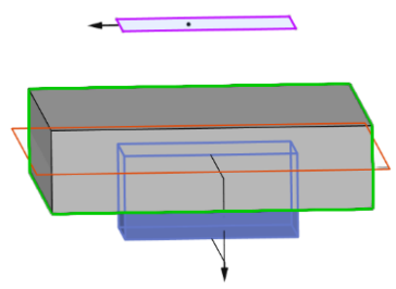
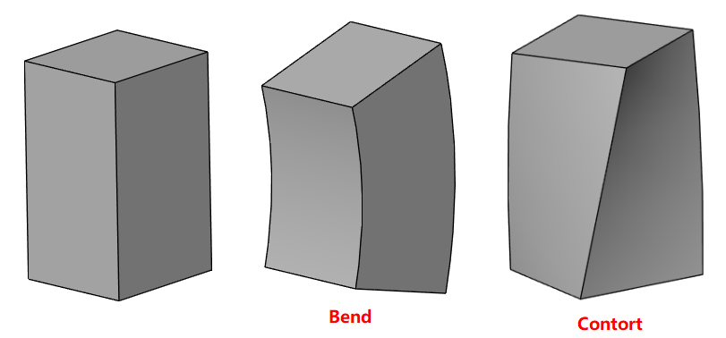
# Bending
Added the ability to bend existing solids/surfaces. This feature supports the bending of existing entities/surfaces with two operation types of "bend and twist", solving the problem of not being able to quickly create distorted geometry.。
How to use:
1) Click to enable the Bend command.
2) Pick up the entity or surface you want to bend (both types of bending and twisting) in the viewport or feature panel.
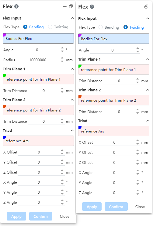
3) Select the type of bend as needed and set the parameters.
4) Click Apply/OK to finish creating.
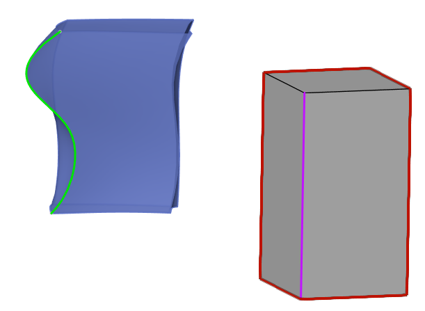
# Morphing
Added the ability to deform existing solids/surfaces. This feature supports "curvilinear to curinear" deformations of existing entities/surfaces, solving the problem that created entities/surfaces cannot be deformed as a whole.
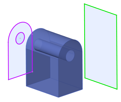
How to use:
1) Click to open the "Deformation" command.
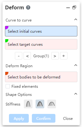
2) Pick Select initial curve and target curve.
3) Click the Control Group button as needed.
4) Pick up the entity/surface you want to deform.
5) You can select the elements to be fixed by checking "Pick Fixed elements" as needed.
6) Click to select Stiffness as needed to control the degree of deformation.
7) Click Apply/OK to complete the creation.
Instructions:
- Control Group button description: "Delete group, previous group, current group, last group, Add group" from left to right. Delete Group is used to delete the current group (keep at least 1 group); Add group is used to add a group (the new group is automatically displayed after the new group is added); When switching between the front and back groups, select the contents of the pick box of the initial/target curve to switch the contents of the corresponding group immediately.

- Stiffness button description: "Minimum, medium (default), maximum" from left to right.

# Solid Blend
Added solid blending feature to quickly create intersecting sections of two cross-sectional stretches. In some simpler models, the model can be fully represented using Outlines in both directions. Using this function, you can quickly create such a model by using the contours of two directions. One feature can realize the creation effect of multiple other features, which greatly improves the modeling efficiency.
How to use:
1) Click to enable the Entity Blending command.

2) Pick up Outline 1 and Outline 2.
3) Check the Outline 1 direction and Outline 2 direction as needed.
4) Click Apply/OK to finish creating.
Instructions:
This parameter is optional. If this parameter is not selected, the direction is the normal of the outline by default. After being checked, the direction pickup box appears, and the contour projection direction can be picked up.
When the selected profile does not have a default normal, this box should be checked automatically, and unchecking it is prohibited.
# Scaling
Added scaling command to support overall scaling geometry.
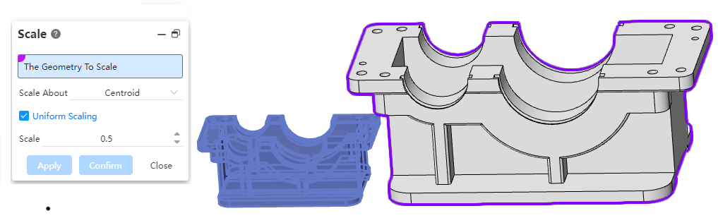
How to use:
1) Click the "Scale to Scale" command in the Transform drop-down menu.
2) Select the geometry you want to scale.
3) Set the scale scaling point, which affects the position of the geometry after scaling.
4) Set the scale scale.
5) Click OK to finish scaling.
Scaling point instructions:
Center of gravity: Each selected geometry is scaled around its respective centroid.
Origin: The selected geometry scales uniformly around the document origin.
Coordinate system: A reference coordinate system needs to be selected, and the selected geometry is scaled around the origin of the selected coordinate system.
Scale description:
Uniform scale: Check this, the XYZ axis is scaled according to uniform scale; Otherwise, the scaling ratio in the XYZ direction can be set separately.
Scale value: 1 to maintain the original scale does not scale, less than 1 to shrink, greater than 1 to enlarge.
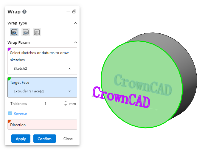
# Cladding
Added wrap command to cover sketch designs to solid surfaces.
How to use:
1) Click the "Wrap" command in the Boolean operation drop-down menu.
2) Select the type of wrap, sketch to wrap, target surface.
3) Set the relevant parameters according to the type of cladding.
4) Click OK to complete the cladding.
Description of the type of cladding:
Embossed: The pattern is coated onto a surface and protrudes outward to a specified thickness, only for solid surfaces. The direction of the bulge can be set.
Etch carving: The pattern is coated onto the surface and then indented to specify thickness, only for solid surfaces. The direction of the indentation can be set.
Marking: The pattern is covered to the surface, and the surface is divided along the pattern path, which can be used for solid surface and curved surface.
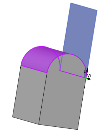
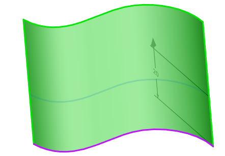
# Surface flattening
Added the function of surface flattening, supporting the flattening of any surface to a specified position. Meet your product design, some maps and other content need to know its shape after expansion, so as to facilitate processing and manufacturing needs.
Use method:
1) Click to open the "Surface Flattening" command.
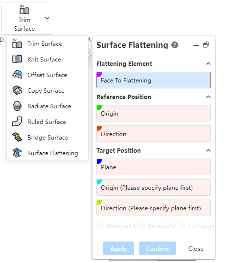
2) Pick up the surface to be flattened.
3) Pick up the elements of the reference position and the target position as needed.
4) Click Apply/OK to complete the flattening.
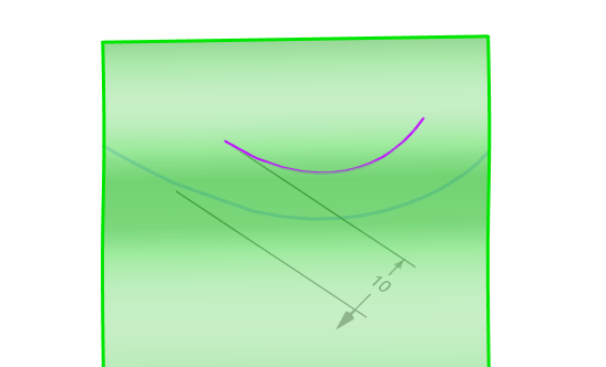
# Parallel curves
Added Parallel Curves feature for creating curves parallel to existing curves at the specified offset distance. Meet the scene you need to generate the target curve on the same surface with the specified offset distance for the curve projected onto the surface or the edge of the face.
How to use:
1) Click to open the "Parallel Curves" command.
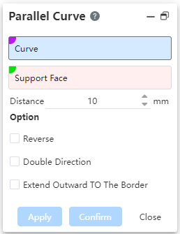
2) Pick up the curve and parallel support surface you want to offset.
3) Set the distance to generate parallel curves.
4) Check options such as "Reverse"/" Bidirectional "/" Extend outward to border "as needed (both are not required).
5) Click Apply/OK to finish the creation.
Instructions:
- After checking "Extend outward to border", the two ends of the curve after parallel automatically extend to the support surface boundary.
# Assembly
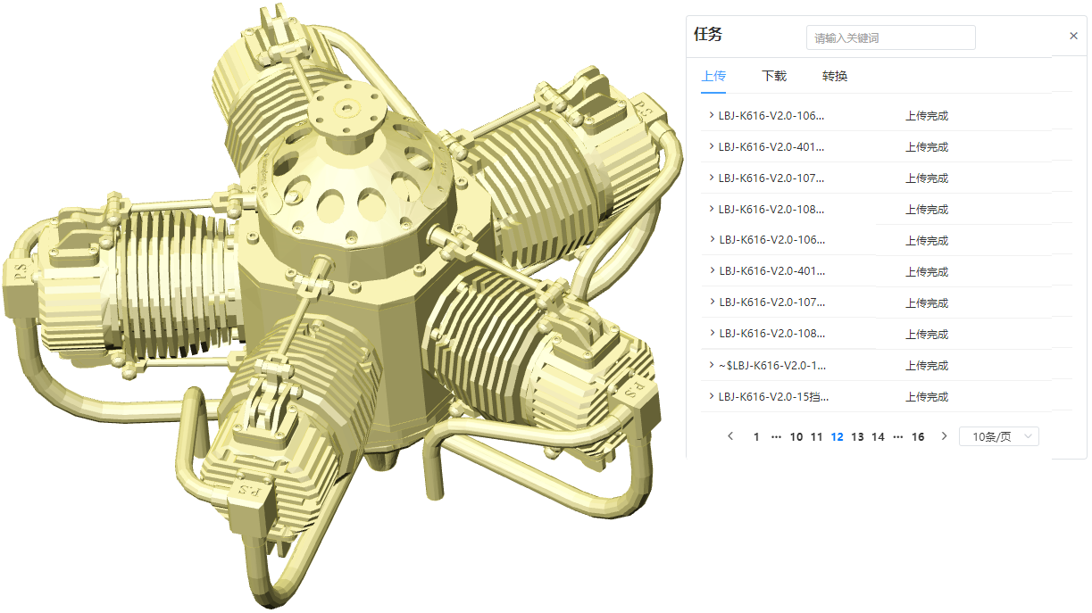
# Document path
New document path feature, support to find parts path.
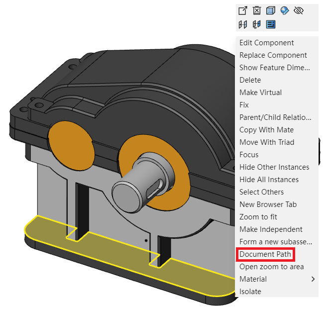
How to use:
1) Right-click the part you want to view the path from in the viewport or feature panel.
2) Click the "Document Path" option.
3) Parts for the current project will open the document list on the right and be highlighted, and parts for other projects will pop up a dialog box showing their path.
# The mirrored parts are associated with the source document
New documents generated by an image in the opposite direction support being associated with the source document.
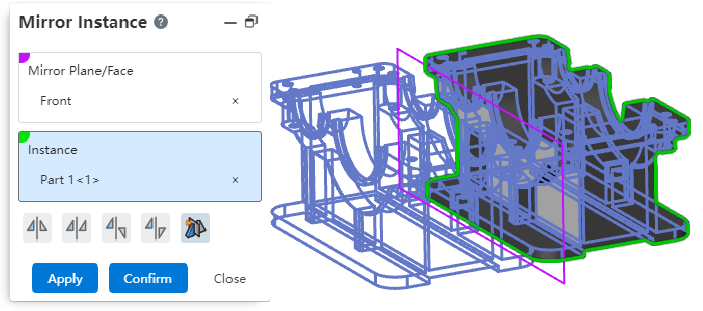
How to use:
1) Create the assembly and insert the parts.
2) Using the image command, select the "Create a new document for the opposite orientation" method to create an image document for the part.
3) Jump to the part document and edit the part.
4) Open the assembly document and view the image document, updated in sync.
# Right click to rotate parts
Supports long right pressing in the viewport to rotate parts.
How to use:
1) Create the assembly and insert the parts.
2) Keep the right button held down on the part you want to rotate without letting go and move the mouse.
3) The parts rotate as the mouse moves.
4) After rotating to the desired position, release the right button to complete the rotation.
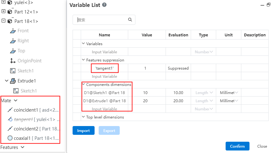
# Fit fit variable management
With adaptive variable management, you can modify the matching parameters and suppress the state in variable management.
# Drawings
# Cutaway view
The cutaway view supports drag and drop to modify the cutaway position.
How to use:
1) Create any section view.
2) Hold the left mouse button on the cutaway view's parent view and drag along the normal of the cutaway view.
3) Release the mouse, end the drag, and update the Secant view.
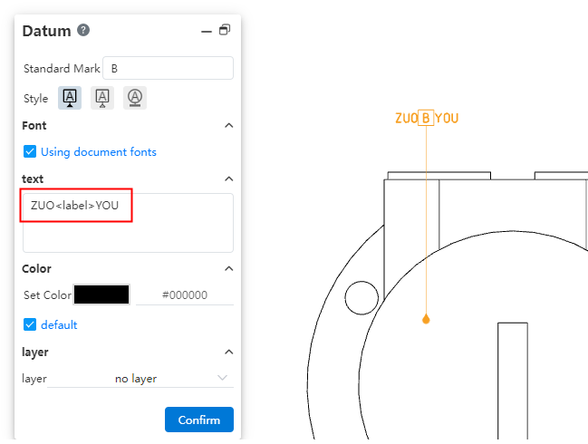
# Benchmark
Benchmark adds a text edit box with support for adding custom text around the benchmark symbol.
How to use:
1) Create baseline annotations.
2) Type text into the Text input box of the dialog box, with <label> in the text box representing where the benchmark label is located.
3) Click OK to finish the creation.
# Part Serial number
Part serial number can be selected, the material list order will be updated.
How to use:
1) Create a material list and part serial number.
2) Select the part serial number you want to modify.
3) In the Part serial number dialog box, use the drop-down box for Item Number to select the serial number.
4) Click "OK" to complete the modification, and the serial number of the material specification sheet is updated with it.
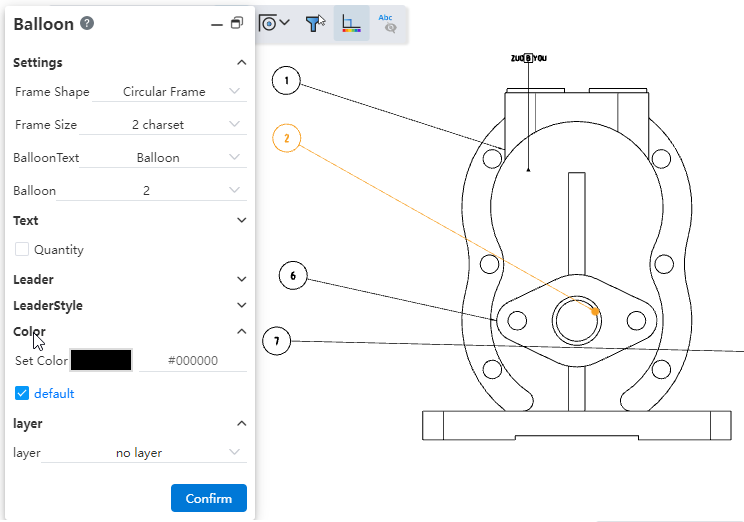
# Notes
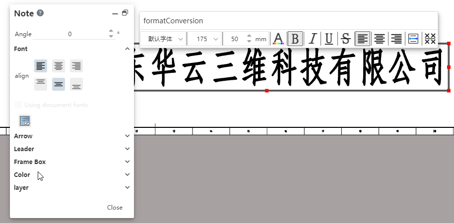
Note editing display border and control label, support setting alignment direction, easy to control the position of the note text.
How to use:
1) Double-click to edit comments.
2) Use the "Align" option in the comment dialog box to set the alignment of the text relative to the border.
3) Drag and drop the red TAB of the border around the text in the viewport to adjust the border position.
4) Click OK to finish the adjustment.
# Drawing format borders automatically
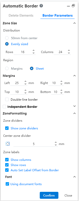
Drawing format automatically adds more parameters to the boundary, and supports the generation of custom picture boxes.
Use method:
1) Enter the Edit Drawing format state and click the "Automatic Boundary" command.
2) Switch to the "Boundary Parameters" Tab.
3) Set the parameters as desired.
4) Click OK to finish creating the boundary.
Parameter description:
Area Size: Set the rules for dividing the area and the total dividing area
Margin: When the total division area is set to "Border", control the distance of the border to the right and left above and below the drawing.
Double-line border: A circle of border lines is generated on the outside of the bounding box to form a double-line border.
Independent border: The margin of the boundary line is the same as the margin of the zone division by default, and you can set a separate margin for the boundary line by checking the independent border.
Zone divider line: Set whether to display zone divider line and the length of zone divider line.
Zone labels: Sets the explicit and hidden status and position of row and column labels.
Font: Sets the font of the zone label.
# Angle labels
Support the selection of three points to mark the Angle, with the sketch Angle mark.
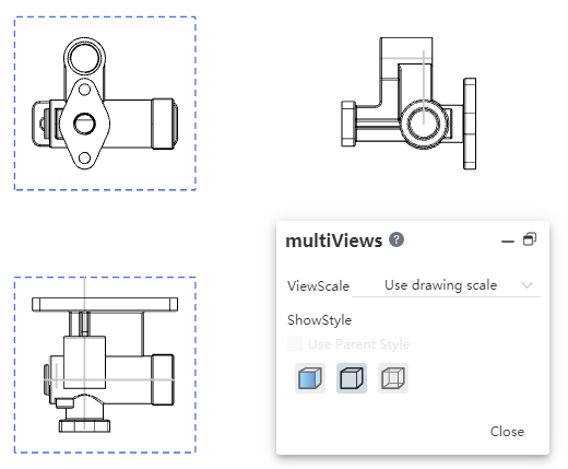
# Read the 3D PMI label
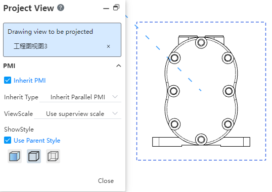
The view supports reading 3D PMI labels.
How to use:
1) Select the view you want to read the 3D PMI annotation from.
2) Select the inheritance type by checking "Inherit PMI" in the dialog box.
3) Click Close to complete the inheritance.
Inheritance type description:
Inherit parallel PMI: Only the PMI that is parallel to the direction of the current view is inherited.
Inherit all PMIs: PMIs in all directions are displayed in the drawing.
Inherited View PMI: Available for preset views and custom perspective views referenced from 3D, displays the PMI labeled on the view when it is activated.
Note: Inherited PMI annotations cannot be edited and modified in the drawing, only the position can be adjusted.
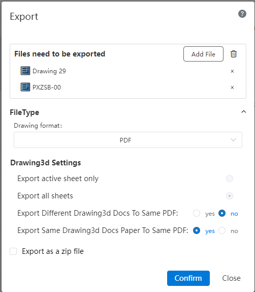
# Export PDF in bulk
When exporting PDF, you can export multiple drawings in batches, and you can set the merging method of drawings.
How to use:
1) Click the Export button in the Import/Export drop-down menu.
2) Use the Add File feature to multiple select the files you want to export.
3) Select PDF as the drawing format.
4) Set whether different drawing documents and drawings from the same drawing document are merged into the same PDF.
5) Click OK to finish exporting.
# Box Select Edit
Support box select the same type of elements, batch edit.
How to use:
1) Select the element you want to edit in the viewport box. Different types of elements have different priorities.
2) When you select elements of the same type, such as views, comments, etc., a dialog box will pop up.
3) Edit in the dialog box, and all elements of the same type are modified simultaneously.
4) Click Close to finish editing.
# Evaluating Tools
# Compare documents
Added the Compare document command, which allows you to compare document properties.
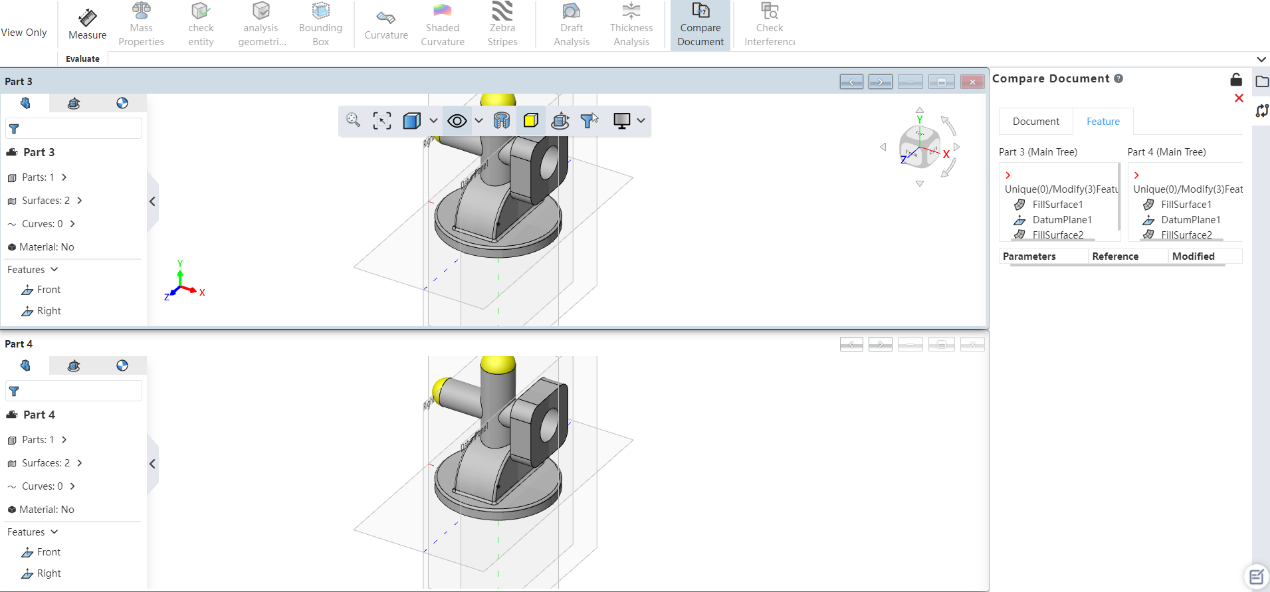
How to use:
1)Click "Document Comparison" in the evaluation module.
2)Select "Reference Document, Compared Document" in the dialog box.
3)Click the Calculate button.
4)Wait for the calculation to finish and the comparison results will be displayed automatically.
5)Click the Exit Comparison button to end the comparison.
# Interference Check
Interference inspection commands support the detection of entities in parts.
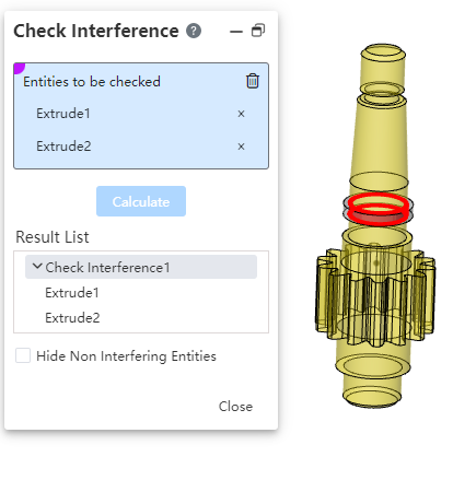
How to use:
1) Click "Interference Check" in the evaluation module.
2) Select the entity you want to check.
3) Click the Calculate button.
4) Wait for the calculation to finish and display the result.
5) Click the close button to end the check.
# Sheet metal
# Side flange
Edge flange editing added support for "Select edge" re-editing, and support for generating reverse edge flanges.
How to use:
1) Right-click the generated edge flange in the feature panel to open the edge flange editing interface.
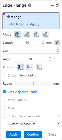
2) You can re-select the edge to generate the edge flange.
3) The flange can be stretched in reverse by clicking the reverse button.
4) Click OK to complete the editing content changes.
# Convert to sheet metal
Conversion to sheet metal supports automatic acquisition of all bends and automatic recognition of wall thickness.
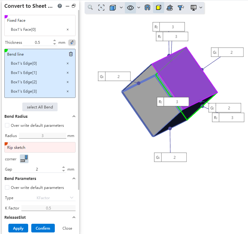
How to use:
1) Click the "Convert to Sheet metal" command of the sheet metal module.
2) Select the imported or otherwise generated entity that you want to convert to sheet metal.
3) Set the fixed surface.
4) Click "Collect All Bends" and the system automatically fills in all available bends and automatically sets the corresponding wall thickness of the entity.
5) Click OK to finish the creation.
# Adaptation Variable Management
Sheet metal features support modification of size and suppression of state in variable management.
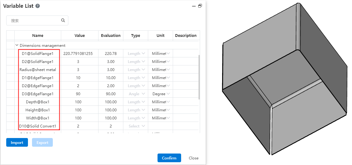
Use the same way as normal features.
# Weldment
# Adaptation variable management
Weldment features support size modification and state suppression in variable management.
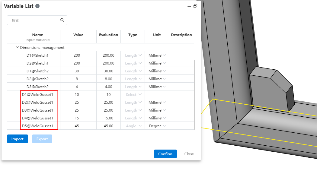
Use the same way as normal features.
# Cable
# Connecting points
The new "connection point" command in the parts document can create connection points for the parts model, so that ordinary parts can be converted into joints of electrical parts, so as to have the function of connecting lines.
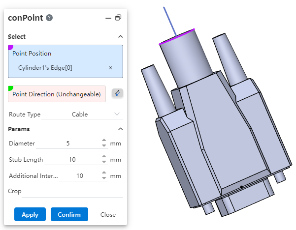
Use method:
1) Import or draw any part model.
2) Go to the path module and click on the Open Connection Point command.
3) Pick up where you want to create connection points, supporting arc lines and points.
4) Select the connection point direction to support the reverse. Note that when the connection point position picks up the arc line, the default is the axis direction, and the direction cannot be selected, but the reverse is supported.
5) Select the type of electrical line.
6) Set the connection point parameters.
7) Click OK to finish the creation.
# Creating the line
New "Create line" command, you can create a line subassembly, and automatically enter the Topdown environment for line editing, as a basic condition to meet your needs to draw lines in the assembly.

How to use:
1) Create/open an assembly document.
2) Go to the cable module and click Open Create Line command.
3) Enter the line name.
4) Click OK to finish the creation.
# Enter/exit the line
Added the "Enter/Exit Line" function to quickly enter or exit the line subassembly document, making it easier for you to edit and exit the created line later.

How to use:
1) Go to the cable module and click Enter Line. The dialog box for selecting a line is displayed.
2) Click to select the line you want to enter

3) Click OK to enter the 3D sketch of the selected line subassembly.
4) Click the Exit Line drop down box to support the option to exit the line or exit the sketch.

# Cable Library
New "Cable Library" feature, you can edit and manage cables. Meet your import, export and custom cable type and style needs.
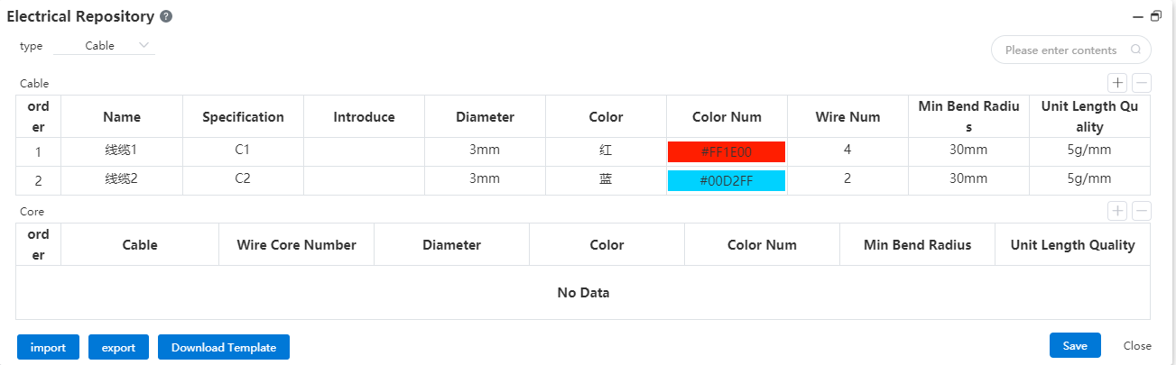
How to use:
1) Go to the cable module and click the "Cable Library" command.
2) Select the line type, both cable and wire types are supported.
3) Create or import the desired cable parameters
4) Click Save to save the cable contents in the cable library.
5) You can export the contents of the cable library to Excel as required.
6) Click the Exit Line drop-down box to support the option to exit the line or exit the sketch.
Note: You can download the template, input cable parameters in batches in the template and import them to the cable library to help you quickly create multiple cables.
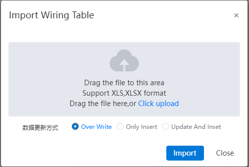
# Wiring List
New wiring table command, you can view the current line information through the wiring table, import and export and edit the contents of the table, automatically insert parts and automatically generate lines to help you quickly complete wiring.
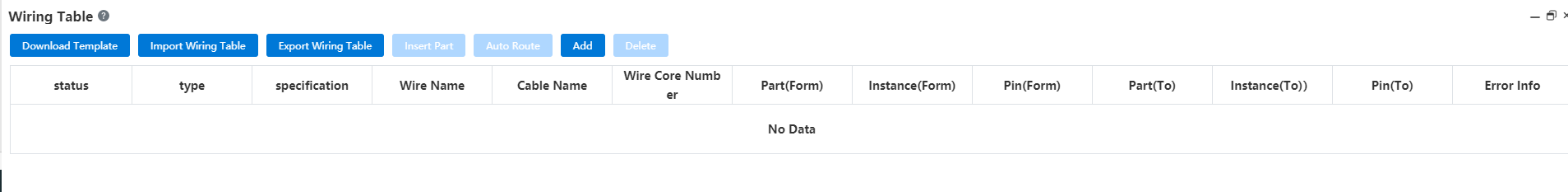
How to use:
1) Go into the line where the wiring is to be done.
2) Click the Wiring Table command in the cable module.
3) Create or edit the wiring sheet information.
4) Click "Insert Part" to open the Insert Part command box.
5) Click Pick Up Part in the Insert Part command box and click anywhere in the viewport to finish inserting.
6) Click Auto wiring to finish wiring the lines in the current wiring table.
Wiring table editing instructions:
Download template: Download the wiring table to the local, you can use the template to edit the wiring table information.
Import cable list: You can import the cable list.excel to the system cable list to quickly create cable information in batches.
- Add/Delete: You can create and delete wiring lines directly in the system wiring table.
# Insert cable
New Insert cable command, free to draw path and generate cable.
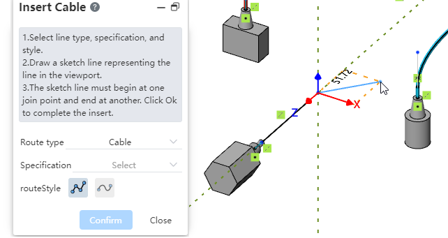
How to use:
1) Go into the line where you want to insert the cable.
2) Click the "Insert Cable" command in the cable module.
3) Select the type and specification of the line you want to plug in.
4) Select a line style that supports straight lines and spline curves.
5) Draw the line in the viewport. Note that it must begin at the point of connection of one part and the path remains continuous until it ends at the point of connection of the other part.
6) Click OK to finish the creation.
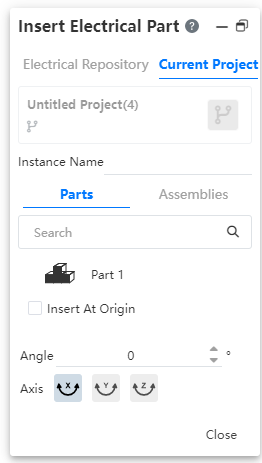
# Insert electrical parts
New "Insert electrical part" command to freely insert desired electrical parts.
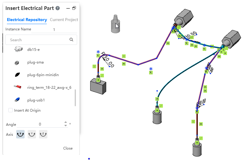
How to use:
1) Go into the wire where the electrical part is to be inserted.
2) Click the "Insert Electrical Part" command of the cable module.
3) Select the electrical part you want to insert in the electrical part library or item.
4) Set the instance name, which is used to distinguish part instances in functions such as wiring tables.
5) Click in the viewport to complete the insertion.
6) Continuous insertion is supported.
7) Click the Close button to end the insertion operation.
Note: Please insert electrical parts using the "Insert electrical parts" function, or the "Insert electrical parts" function in the wiring sheet to ensure that the system can correctly identify electrical parts and perform wiring, statistics, etc.
# Edit the wire
Added "Edit Wire" function, you can edit, modify and add wire.
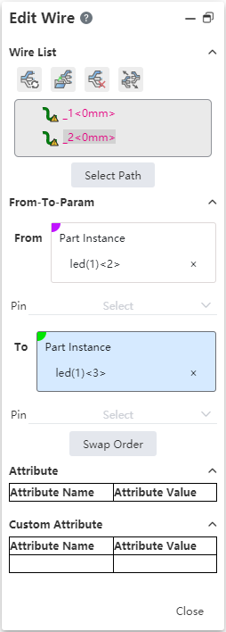
Dialog box description:
Refresh Wires: Rebuild wires and cables throughout the line.
Add Wire: Click to select a line specification to add to the current line.
Remove Wires: Select cables from the list and click this to remove the selected cable.
Replace wire: select cable in the list, click the to modify of the specifications of the cables.
Wire List: Shows the wires and cables present in the current line.
Select a path: Select the cable in the list and click to specify a path for it in the dialog box that pops up.
From - to - Parameters: Display and set the part instances from and to as well as pin numbers.
Swap order: Click to swap the contents of from - to -.
Properties: Displays the preset electrical properties of the line.
Custom properties: You can add your own properties as needed.
Wire List Line status:
 :Normal line.
 :An error exists on the path.
 :Path not specified.
Note: When you specify a path, the path must be continuous and connected from the connection point of one part instance to the connection point of another part instance.
# Statistical tables
Added the "Statistical Table" command to display the line information in the table according to the predetermined rules.
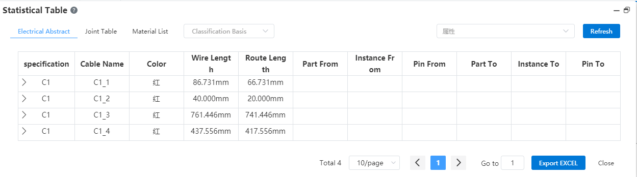
How to use:
1) Go to the line where you want to view statistics.
2) Click the Statistics Form command.
3) Select the type of table you want to view.
4) You can export the table as an EXCEL spreadsheet file if you want.
Table type instructions:
Circuit Summary: Displays all line information in the current line.
Connector table: Select a connection instance in the current line and view the connection information of the connection instance.
Material specification table: shows the parts and lines in the sub-assembly of the wire, and shows the same specification lines.
# Quick design
New Quick design module for quickly creating "cylindrical gears, bevel gears".
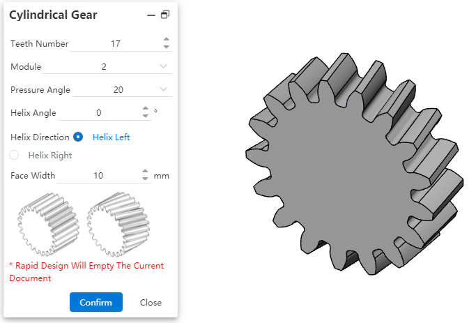
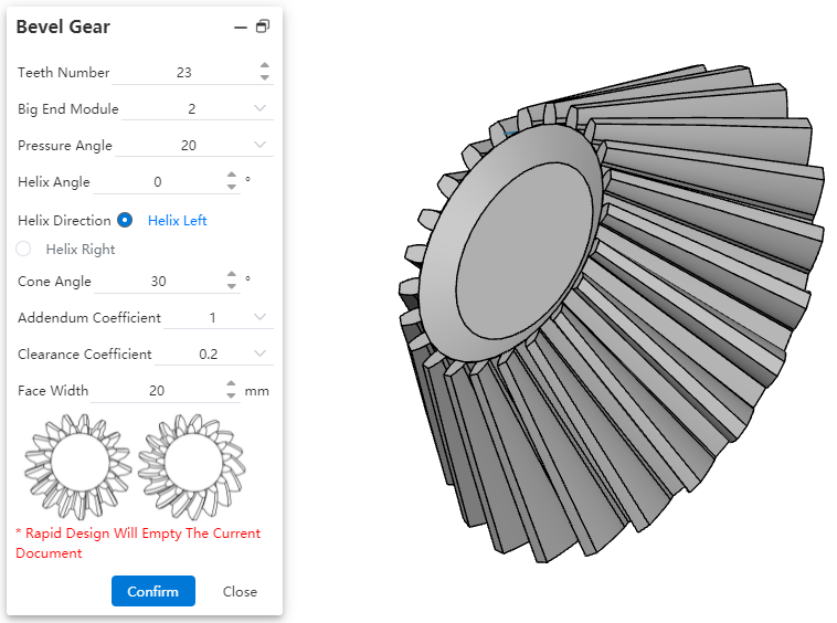
How to use:
1) Click the "cylindrical gear, bevel gear" command of the quick design module to pop up the dialog box.
2) Set gear parameters in the dialog box.
3) Click the OK button and wait for the system to finish creating the model.
Note: The Quick Design feature will create the model after clearing the current document, be sure to confirm that there is no data in the current document that you need to keep before using.
# Direct editing
New Direct editing module that provides commands for editing models directly.
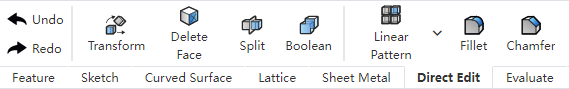
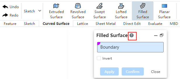
Note: In the command dialog box, click the question mark icon to jump to the help manual of the command.
# Point Cloud
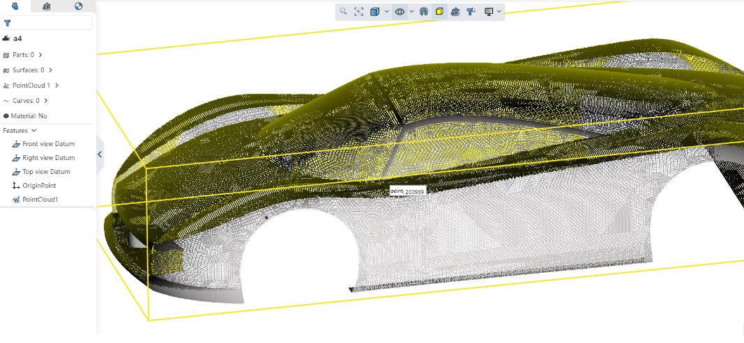
# Importing point clouds
Added the function of importing point cloud model file, supporting *.xyz; *.asc; *.ply; *.pcd four formats.
Import the same way you import other model files.
# Positioning
New positioning feature that can be used to adjust the position and orientation of the point cloud model relative to the origin.
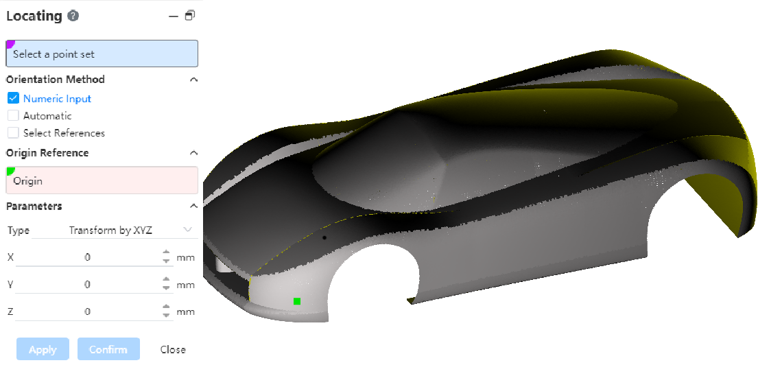
How to use:
1) Click the "Location" command of the point cloud module to pop up the location dialog box.
2) Select the point cloud model you want to locate.
3) Select the positioning method and set the parameters.
4) Click OK to complete the location.
The positioning method description:
Setting parameters: refer to the "transform" function of the feature of the part, and locate by specifying parameters.
Automatic positioning: The system automatically locates the model based on the center of gravity and the inertial spindle, and the center of gravity is the "origin".
Select the positioning reference: Position the model by specifying the origin, XY direction.
Set reference origin: Pick up a point in the point cloud model that coincides with the document origin.
Parameter setting: Different parameters are displayed according to different positioning methods.
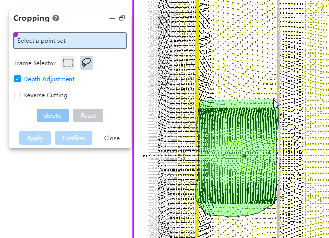
# Remove superfluous points
Added Delete redundant points function, which can delete redundant points generated during point cloud scanning.
How to use:
1) Click the "Location" command of the point cloud module to pop up the location dialog box
2) Select the point cloud model you want to locate.
3) Depending on the shape you want to remove, select the appropriate box picker.
4) Select the area in the viewport box where you want to delete the point cloud.
5) If you want to modify the "depth" of the deletion, check "Select Depth Adjustment".
6) Drag the green square TAB in the viewport to adjust the depth.
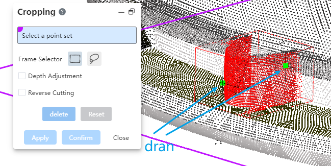
7) Set whether to reverse lateral resection as required. Check: Delete box select outside the range point cloud; Unchecked: Delete the point cloud within the range.
8) Click OK to complete the culling operation.
# Remove noise
Add the "Remove noise" command to remove discrete points with large errors.
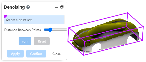
How to use:
1) Click the "Remove noise" command of the point cloud module to pop up the dialog box
2) Select the point cloud model that you want to remove noise from.
3) Set the deviation distance.
4) Click Calculate to see a preview in the current deviation distance.
5) Adjust the deviation distance as needed and repeat steps 3 to 4 to get a satisfactory preview.
6) Click OK to finish de-noising.
# Simplify
New "simplify" function, improve model processing efficiency, optimize data quality, and provide guarantee for the subsequent point cloud to high-quality grid.
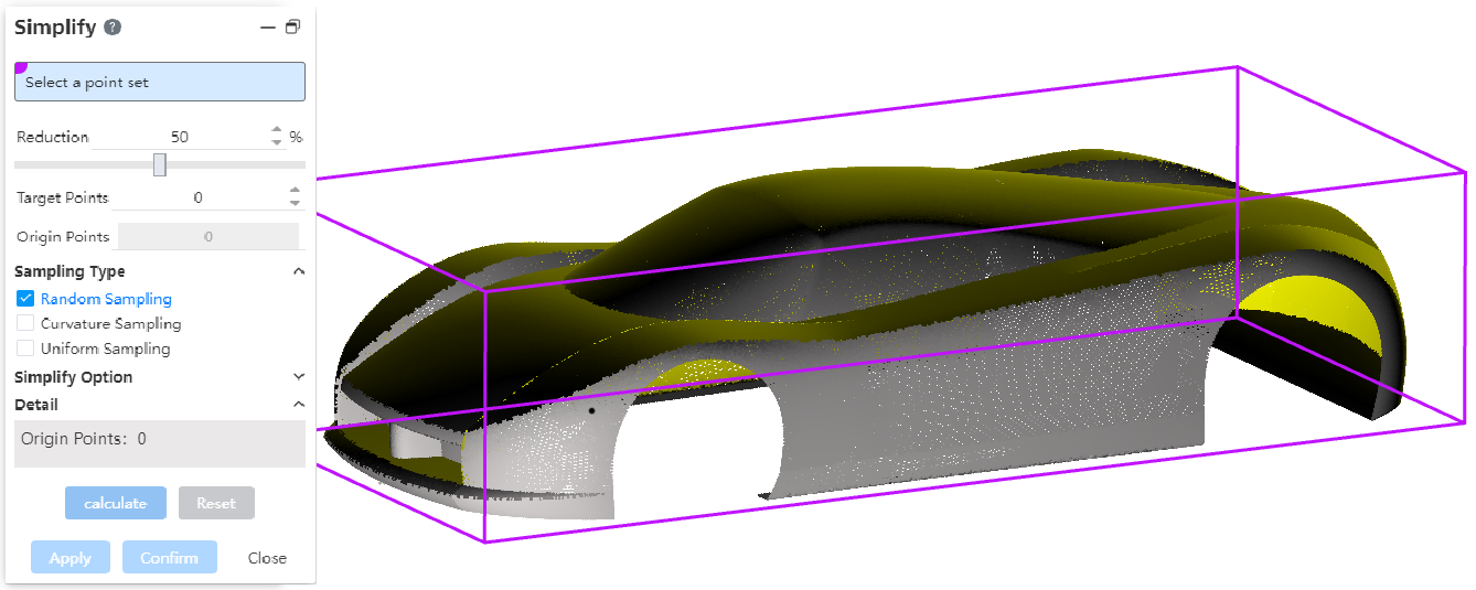
Usage:
1) Click the "Simplify" command of the point cloud module to pop up the dialog box
2) Select the point cloud model you want to simplify.
3) Set scaling down or target points, sampling method, and simplification options.
4) Click Calculate to view the simplified preview
5) Adjust the parameters as needed and repeat steps 3 to 4 to get a satisfactory preview.
6) Click OK to finish simplifying.
Dialog box description:
Reduction ratio, target points: the two are related to control how many points to cut this simplification.
Sampling method: Optional "random sampling, curvature sampling, uniform sampling", affect the simplification algorithm, different methods will obtain different simplification effects.
Simplified options: Control whether to "permanently delete simplified points", when checked, the simplified points are permanently deleted and can no longer edit parameters.
Simplified details: Displays information about simplified points.
# Gridding
Added the "Grid" command to support the conversion of point cloud data to grid data.
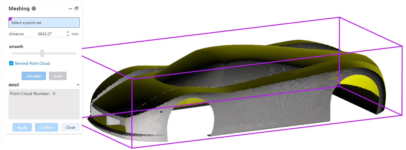
How to use:
1) Click the "grid" command of the point cloud module to pop up the dialog box
2) Select the point cloud model you want to grid.
3) Set the distance between points, the smoothness, and whether to keep the point cloud data.
4) Click Calculate to see the preview under the current parameters as well as the number of triangle pieces.
5) Adjust the parameters as needed and repeat steps 3 to 4 to get a satisfactory preview.
6) Click OK to finish meshing.
Dialog box description:
Distance between points: the length of the sides of the triangular pieces in the generated grid model.
Smoothness: Drag from left to right, gradually increasing the smoothness.
Keep point cloud data: Check to keep point cloud data after conversion; Uncheck, delete point cloud data after conversion.
# Data conversion
# obj format
obj model conversion supports retaining model textures.
How to use:
1) Package the obj model with the associated texture pictures as a zip zip package.
2) Upload the zip package.
3) View the obj model after the conversion is complete.
# dgn Format
Added support for converting 3D model files in dgn format.
# Collaboration
# Team project ownership can be transferred when the team is dissolved
Team project ownership can be transferred when a team is dissolved.
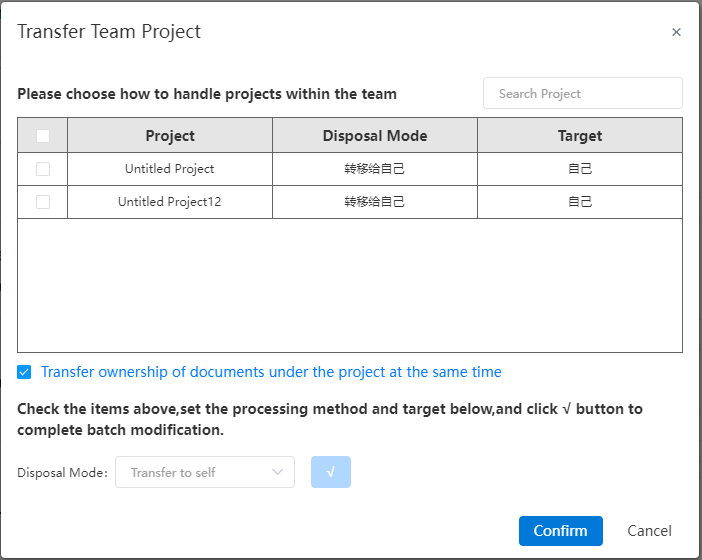
How to use:
1) Open the team you want to disband in the Team Management screen.
2) Click Delete Team and confirm.
3) The Team Project Ownership Transfer dialog box is displayed.
4) Check the intra-team items you want to set up in the dialog box and select how to handle them below. Support the "Transfer to yourself, Transfer to team, Transfer to User, Delete" mode.
5) Click "√" to finish setting the processing method for the selected items.
6) Repeat Steps 4 to 5 to complete the processing Settings for all items.
7) Click "Confirm" the team ownership is transferred as set and the team is deleted.
# MBD
# Size type
MBD module added "dimension chain, reference size, arc length size, chamfer size" dimension type annotation.
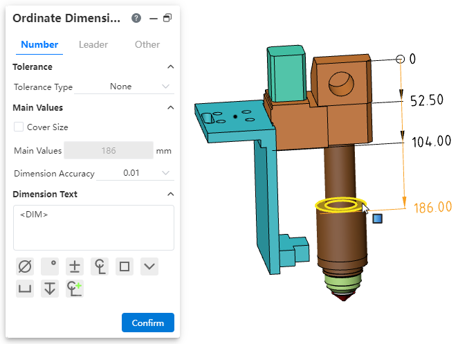
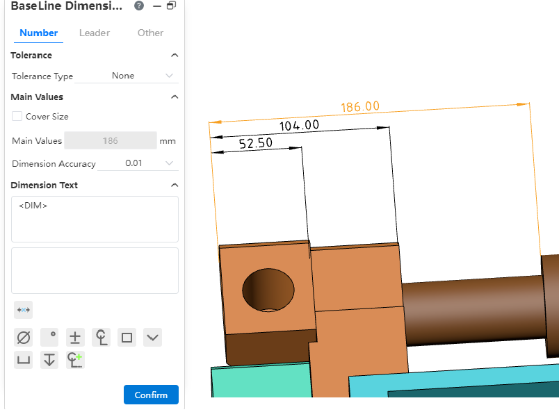
How to use:
1) Activate the view in which you want to place the MBD by right-clicking in the "View Panel" on the left side of the viewport.
2) Click the annotation you want to create in the MBD module.
3) Select "Point, line, surface" in the viewport to mark.
4) Annotation interaction and dialog box can set the item reference engineering drawing annotation.
# Supporting elements
The MBD labeling command support element has been expanded to support the creation of dimensions, datums, form and position tolerances, roughness, welding symbols, and datums on the "point, line, and surface" element.
# Datum
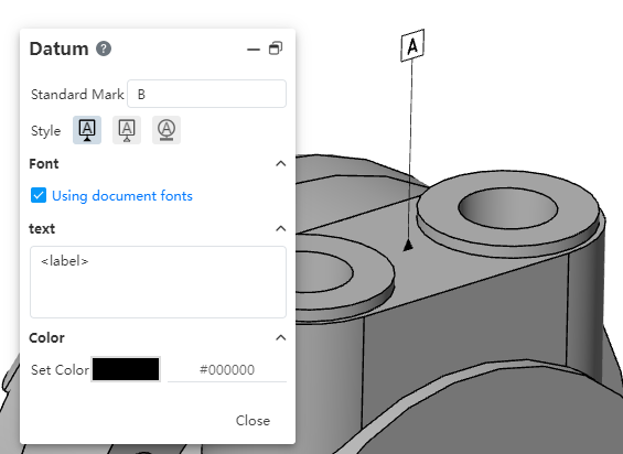
Benchmarks support adding your own text around labels.
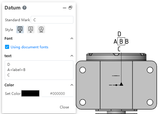
How to use:
1) Create baseline annotations.
2) Type text into the Text input box of the dialog box, with <label> in the text box representing where the benchmark label is located.
3) Click "ok", complete to create.
# Tools
# Mouse cursor
When sketching, the mouse cursor will display the corresponding icon according to the current command.
# Save the document
New Save document feature to save a currently open document as a new document.
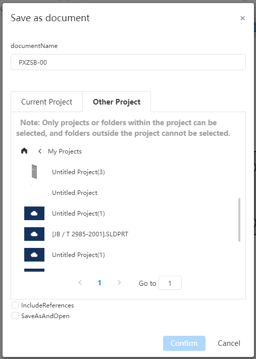
How to use:
1) With the document open, click the "Save Document" option in the drop-down menu of the Save icon.
2) Set the name of the new document you want to generate in the Save Document dialog box.
3) Set the location of the new document you want to save.
4) Set whether to "Include all reference documents" : Check it and copy both the current document and the referenced reference document; Uncheck and only copy the current document. This is available for assembly and engineering drawing documents.
5) Set whether to "Save and open" : check to open a new document after copying; Unchecked, only copy without opening new document.
6) Click "OK" to finish saving the document.
# Pack
Support packaging and copying parts, assemblies, drawings, and associated documents. You can use this feature to quickly gather associated documents together and create copies for easy modification or archiving.
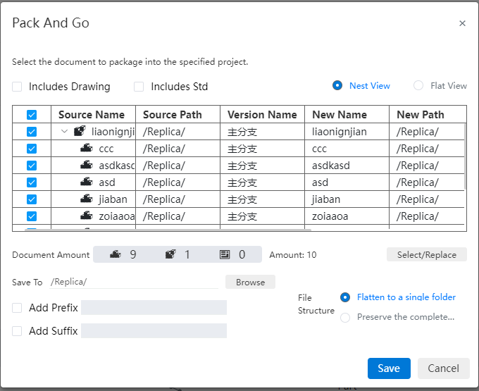
How to use it:
1) Click the Pack command that saves the drop-down menu
2) Set what to pack, whether to include drawings, standard parts, etc., in the dialog box
3) Change the packing location by browsing
4) Add prefix, Add suffix: Type text into the input field after checking, then press Enter to add uniform presuffix to each new name.
5) Click Save to complete the corresponding packaging.
# Apply
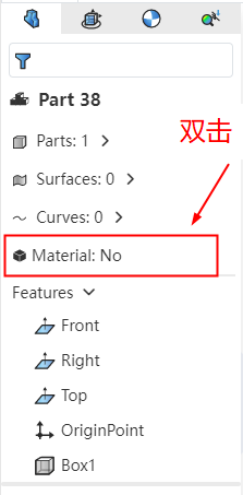
# Double-click to open the Material library
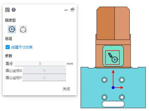
Double-click "Material" in the feature panel to quickly open the material library.
# Quickly modify standard part specifications
Click on a standard part that has been inserted in the assembly to quickly modify the specifications in the pop-up menu.

How to use:
1) Insert standard parts in assembly using the standard Parts library function.
2) Click the standard part that has been inserted in the viewport.
3) A shortcut menu appears near the mouse.
4) Click the drop-down box in the shortcut menu to switch other specifications of the standard part.
# Render
# Pick Up
When transparent rendering, support to select other elements that are obscured by transparent surface.
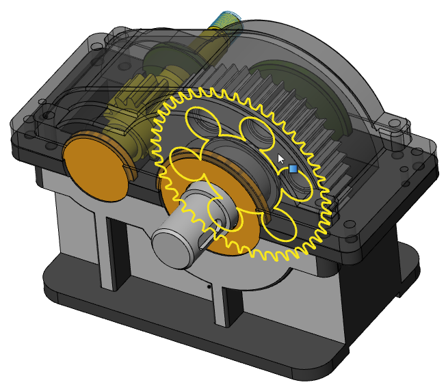
How to use:
1) Open the "System Settings - Selection" page and make sure the "Enable selection through Transparent surfaces" option is checked.
2) Set the face/part to translucent using the translucent feature of the Set Appearance or right-click menu.
3) Penetrate the translucent face to pick up other elements that are being obscured.
Note: Other elements must be opaque to be picked up.
# Isolate
Support for isolating solids/surfaces in parts to temporarily view specific geometry separately.
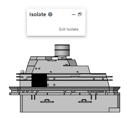
How to use:
1) Right click on the entity/surface in the feature panel or viewmouth.
2) Click "Isolate" from the right-click menu.
3) Enter the "Isolated" state where other entities/surfaces are hidden and only the selected entity/surface is displayed.
4) Click Exit Isolation to return to the default state.
# Project Documentation
# Transfer of ownership
Added the transfer ownership function. When personnel transfer or project resource adjustment occurs, you can use this function to change the owner of the project or document.
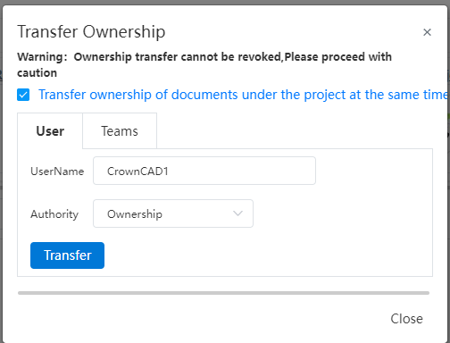
How to use:
1) Right-click an item or document that needs to transfer ownership.
2) Click the "Transfer Ownership" option.
3) In the "Transfer Ownership" dialog box, use the "Users, Teams" Tab page to toggle transfer to users or teams.
4) Set the target user, team.
5) Click "Transfer" to complete the ownership transfer.
Note: When transferring the project, check "Transfer the ownership of documents under the project at the same time" to transfer the ownership of the project and all documents within the project at the same time; Otherwise, only the ownership of the project is transferred, and the ownership of the document remains unchanged.